Table of Contents
Advertisement
Quick Links
Advertisement
Table of Contents

Related Manuals for Nellcor OxiMax N-65


Summary of Contents for Nellcor OxiMax N-65
- Page 1 N-65...
- Page 2 To obtain information about a warranty, if any, contact Nellcor’s Technical Services Department, or your local representative. Purchase of this instrument confers no express or implied license under any Nellcor Puritan Bennett patent to use the instrument with any sensor that is not manufactured or licensed by Nellcor Puritan Bennett.
-
Page 3: Table Of Contents
Description of OXIMAX N-65 ........ - Page 4 Contents Test 4: Light Level ..........36 Safety Tests .
- Page 5 Contents Block Diagram Theory ..........84 Printed Circuit Board .
- Page 6 Contents N-65 Service Manual...
-
Page 7: Introduction
I n t r o d u c t i o n Warnings Warnings are identified by the WARNING symbol shown above. Warnings alert the user to potential serious outcomes (death, injury, or adverse events) to the patient or user. WARNING: The sensor uses the date and time provided by the O N-65 handheld pulse oximeter when the sensor event record is recorded by the... -
Page 8: Cautions
Introduction WARNING: As with all medical equipment, carefully route patient cabling to reduce the possibility of patient entanglement or strangulation. WARNING: To ensure accurate performance and prevent device failure, do not expose the monitor to extreme moisture such as rain. Cautions Cautions are identified by the CAUTION symbol shown above. -
Page 9: Manual Overview
Introduction Manual Overview This manual contains information for service personnel who will service the Nellcor model O N-65 handheld pulse oximeter, herein referred to as the monitor. Only qualified service personnel should service this product. Read the operator's manual carefully and thoroughly understand the operation of the monitor. -
Page 10: Description Of Oximax N-65
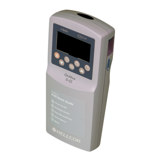
Introduction Description of O N-65 The O ™ N-65 handheld pulse oximeter is indicated for continuous or spot check monitoring of functional arterial oxygen saturation (SpO ) and pulse rate of adult, pediatric and neonatal patients in hospital, hospital-type facilities, transport and mobile environments as well as in the homecare environment. - Page 11 Introduction 5 — %SpO Lower Alarm Limit indicator 6 — %SpO Upper Alarm Limit indicator 7 — Pulse Amplitude indicator (Blip bar) 8 — Time Colon time/date field separator 9 — Adjust Time mode indicator 10 — Adjust Volume mode indicator 11 —...
- Page 12 Introduction 17 — Low Battery indicator 18 — Data In-Sensor indicator 19 — Alarm Volume Adjust indicator 20 — Pulse Beep Tone Volume Adjust indicator 21 — BPM Lower Alarm Limit indicator 22 — Print indicator 23 — Interference indicator 24 —...
- Page 13 Introduction 27 — Power button 28 — Up Arrow button 29 — Backlight button 30 — Menu button 31 — Data (Record/Print) button 32 — Down Arrow button 33 — Alarm Silence button N-65 Service Manual...
-
Page 14: Front Panel Symbols
Introduction Front Panel Symbols The follow two symbols are located on the front panel of the monitor. Displays the measured percent of oxygen saturation. Displays the measured pulse beats per minute. Rear Panel Symbols The following symbols are located on the rear panel of the monitor. 1 —... -
Page 15: Label Symbols
Introduction Date of Manufacture European union approval Canadian/USA certification mark (electrical safety) Russian regulatory approval Serial number Label Symbols These symbols display on the monitor’s labels. Keep away from heat Temperature limitation Protect from moisture Fragile Keep upright Humidity limitation N-65 Service Manual... -
Page 16: Menu Parameters
Introduction Menu Parameters This section contains information on how to set monitor parameters and limits using the menu structure. See Set Menu Parameters on page 11 to set the following parameters: • high and low SpO limits • high and low BPM limits •... -
Page 17: Set Menu Parameters
Introduction Set Menu Parameters To set menu parameters, press the Menu button repeatedly during normal operation to display the parameters to set. Use the Up Arrow button or Down Arrow button to adjust the parameter limit. Press the Menu button to return to the default monitoring display. -
Page 18: Set Time/Date Parameters
Introduction WARNING: Do not silence the O N-65 audible alarm, or decrease its volume, if patient safety could be compromised. Set Time/Date Parameters To access the Time/Date settings menu, press the Menu button during start-up Power-On-Self-Test (POST). Press the Menu button repeatedly to display the time/date parameters to set. - Page 19 Introduction Table 2: Time Set Menu # of Parameter Press Function Presses The Menu button must be pressed during the POST. Hour Adjust 1 to 23 Minute Adjust 1 to 59 Adjust 1 to 31 Month Adjust 1 to 12 Year Adjust 2003 to 2099 N-65 Service Manual...
-
Page 20: Related Documents
O N-65. Refer to the O N-65 Operator's Manual. To understand the various Nellcor approved O sensors that work with the monitor, refer to the individual O sensor's Directions For Use. -
Page 21: Routine Maintenance
24 months. To perform periodic safety checks: 1. Inspect the equipment for mechanical and functional damage. 2. Inspect safety labels for legibility. If the labels are damaged, contact Nellcor’s Technical Services Department, 1.800.635.5267, or your local Nellcor representative. Functional Checks If the monitor has been visibly damaged or subjected to mechanical shock (for example, if dropped), immediately perform the performance tests. -
Page 22: Battery Installation
Routine Maintenance Battery Installation Caution: The monitor does not operate with dead batteries. Install new batteries. To install new batteries: 1. Press the Power button to turn the monitor off. 2. Pull the battery compartment latch downward, toward the bottom of the monitor, and remove the battery access door. -
Page 23: Performance Verification
Caution: If any indicator or display element does not light when the monitor is turned on, do not use it. Instead, contact qualified service personnel, your local Nellcor representative, or Nellcor’s Technical Services Department. Note: Physiological conditions, medical procedures, or external agents that may interfere with the monitor’s ability to detect and display accurate measurements... -
Page 24: Procedure
Performance Verification Caution: During POST (immediately after power-up), confirm that all display segments and icons are shown, and the monitor speaker sounds a one-second tone. When the monitor is turned on, the backlight remains on. The display displays the following sequence, in order, as POST takes place: •... - Page 25 Performance Verification 2. The display goes blank for one second. 3. The software version number displays. The software version is identified by two dashes in the %SpO area of the display. Note: The software version 001 is an example. Check the monitor for the software version installed.
- Page 26 Performance Verification Note: If the time has never been set, do not continue until you set the time. See Operator’s Manual. 5. If the monitor detects a problem, an error tone sounds and an error code (Er) and the error number display. See Troubleshooting on page 39. 6.
- Page 27 Performance Verification Note: In addition to serving as the POST pass verification, the POST pass tone also functions as audible confirmation that the speaker is performing properly. If the speaker does not function, the alarm warning sounds cannot be heard. 7.
-
Page 28: Operational Setup
Performance Verification Operational Setup The operational setup procedure sets the time and date into the monitor. Refer to the O N-65 Operator’s Manual for individual parameter settings. The monitor returns to the factory default settings when it is powered on: therefore, individual parameter settings need to be set at that time. - Page 29 Performance Verification 3. Press the Menu button during the POST operation until the set hours window appears with the hours indication (13) flashing. 4. Press the Up Arrow button or the Down Arrow button until the desired hours appear. 5. Press the Menu button to set the hours and show the minutes set display. The minutes indication (45) flashes.
- Page 30 Performance Verification 7. Press the Menu button to set the minutes and show the day set display. The day indication (29) flashes. 8. Press the Up Arrow button or the Down Arrow button until the desired day appears. 9. Press the Menu button to set the day and show the month set display. The month indication (7) flashes.
- Page 31 Performance Verification 11. Press the Menu button to set the month and show the year set display. The year indication (2004) flashes. 12. Press the Up Arrow button or the Down Arrow button until the desired year appears. 13. Press the Menu button to set the year and return to normal operation. N-65 Service Manual...
-
Page 32: General Operation
Sensor Port — To connect the O sensor to a live subject for a qualitative test: 1. Connect a Nellcor O MAX-A oxygen O sensor to the monitor. 2. Clip the MAX-A to the subject as recommended in the O sensor's Directions For Use. - Page 33 Performance Verification The monitor records snap-shot data. 6. Turn off the monitor. N-65 Service Manual...
-
Page 34: Pulse Oximetry Functional Tests
Performance Verification Pulse Oximetry Functional Tests The Pulse Oximetry Functional Tests utilize the pulse oximetry functional tester (Nellcor model SRC-MAX) to verify the performance of the monitor. See Figure 2. 1 —O N-65 Cable Connector 6 — % Modulation Select Button 2 —... - Page 35 Performance Verification The SRC-MAX functional tester allows qualified technicians to functionally test Nellcor O technology-based pulse oximeters and OEM O technology-based monitors. The Pulse Oximetry Functional tests should be completed in the order shown: • Test Setup Note: The technician must complete Test Setup before performing tests 1 through 4 as follows.
- Page 36 Performance Verification Table 3 shows the Pulse Oximetry Functional Tests you must perform and a description of each. Table 3: Pulse Oximetry Functional Tests Test Description Test Setup This procedure establishes the baseline for all the other tests. Test Setup must be performed before performing any or all of the SRC-MAX tests.
-
Page 37: Test Setup
Performance Verification Test Setup You must complete Test Setup before performing any other pulse oximetry functional tests. To perform test setup: 1. Press the Power button to turn on the monitor. 2. After the monitor presents the monitoring screen, connect the SRC-MAX tester to the monitor sensor port as shown. -
Page 38: Test 1: Bpm
Performance Verification • Pulse Amplitude indicator - displays low level modulation (low amplitude pulse amplitude indicator) Test 1: BPM To perform Test 1: BPM: 1. Press the SRC-MAX % Pulse Rate selection button. The SRC-MAX Pulse Rate 200 LED lights. The monitor bpm increases to 200 and stabilize at 200 bpm. -
Page 39: Test 2: Spo2
Performance Verification 2. Press the SRC-MAX Pulse Rate select button. The SRC-MAX Pulse Rate 60 LED lights. The monitor pulse rate decreases to 60 and stabilize at 60 bpm. The test pass criteria is 57 to 63 bpm inclusive. The monitor: •... -
Page 40: Test 3: Modulation Level
Performance Verification 2. Press the SRC-MAX %SpO select button. The SRC-MAX %SpO 75 LED lights. The monitor displays two dashes until the SRC-MAX stabilizes at 75 %SpO The test pass criteria is 73 to 77 %SpO inclusive. The monitor: • displays 75 %SpO (pass criteria is 73 to 77 %SpO inclusive) - Page 41 Performance Verification 2. Perform Test 1: BPM on page 32. The Pulse Amplitude indicator should indicate high level modulation. 3. Perform Test 2: SpO2 on page 33. The Pulse Amplitude indicator should indicate high level modulation. 4. Press the SRC-MAX % Modulation selection button. The SRC-MAX % Modulation LED lights.
-
Page 42: Test 4: Light Level
Performance Verification Test 4: Light Level To perform Test 4: Light Level: 1. Press the SRC-MAX Light Level selection button. The SRC-MAX Light Level LED lights. The monitor pulse blip bar initially increases in amplitude and then reduces and stabilizes at 3-5 bars. The monitor: •... -
Page 43: Safety Tests
Performance Verification 4. Press the SRC-MAX Light Level selection button. The SRC-MAX Light Level LED lights. The monitor pulse blip bar initially increases in amplitude and then reduces and stabilizes at 3-5 bars. The monitor: • displays 75 %SpO • displays 60 bpm •... - Page 44 Performance Verification N-65 Service Manual...
-
Page 45: Troubleshooting
Table 4: Troubleshooting Guide, on page 40. In the table, find the condition that describes the problem and follow the corrective actions in the order presented. For a symptom that is not listed in Table 4, contact the Nellcor Technical Services Department at 1.800.635.5267 or your local Nellcor representative. - Page 46 Troubleshooting If an error code is shown on the monitor front panel display, see Figure 3. Turn the monitor off, wait ten seconds, then turn it back on. This clears recoverable errors encountered by the monitor. If the error code persists, refer to Table 5: Error Codes, on page 43 for an explanation of the error code.
- Page 47 Replace the User Interface PCB. See SpO2 PCB or User problem. Interface PCB Replacement on page 50. If this does not fix the problem, return the monitor to Nellcor. One or more keys on the front panel keypad does not work. • The flex circuit between the front panel...
-
Page 48: Error Codes
Replace the User Interface PCB. See SpO2 PCB or User problem. Interface PCB Replacement on page 50. If this does not fix the problem, return the monitor to Nellcor. • The Backlight LEDs on the User Replace the User Interface PCB. See SpO2 PCB or User Interface PCB have failed. - Page 49 Troubleshooting Table 5 provides a list of error codes for the monitor. Table 5: Error Codes Scope of Action Error Action Explanation Code Replace SpO board. front end RAM error. Replace SpO board. front end ROM/code integrity error. Replace SpO board.
- Page 50 Troubleshooting Table 5: Error Codes (Continued) Scope of Action Error Action Explanation Code Replace SpO board. back end reports packet start ID (SID) missing. Replace SpO board. back end reports packet length error. Replace SpO board. back end reports message length error.
- Page 51 Troubleshooting Table 5: Error Codes (Continued) Scope of Action Error Action Explanation Code Replace UI board. Communication failure with real time clock. Replace UI board. Real time clock oscillator control problem. Replace UI board. Real time clock failed timing test. Replace UI board.
- Page 52 Troubleshooting Table 5: Error Codes (Continued) Scope of Action Error Action Explanation Code 1 — Restart the monitor. Erroneous key press detected at start. 2 — Replace membrane switch pad. Replace UI board. Fatal system error reading memory. Return monitor for repair. Fatal software error.
-
Page 53: Disassembly Guide
D i s a s s e m b l y G u i d e Introduction The O N-65 can be disassembled into all major component parts, including: • Front case with front panel keypad • Rear bottom • User Interface PCB •... -
Page 54: Prior To Disassembly
Disassembly Guide Prior to Disassembly The monitor batteries must be removed prior to disassembly. To remove the batteries: 1. Press the Power button to turn the monitor off. 2. Remove the battery cover. 3. Pull the battery cover latch downward toward the bottom of the monitor case and lift the battery cover. - Page 55 Disassembly Guide 2. Remove the four screws holding the monitor front and rear cases together. See Figure 5, items 1 through 4. Figure 5: Monitor Case Screws Caution: A flex cable runs between the monitor front and rear case assemblies. Use care when separating the cases. Do not apply stress to the flex cable.
-
Page 56: Spo2 Pcb Or User Interface Pcb Replacement
Disassembly Guide 4. Unlock connector J4 on the SpO PCB. See Figure 6 and Figure 7. 1 — SpO PCB . 2 — J4 lock 3 — Lock direction 4 — Unlock direction Figure 7: SpO PCB Connector J4 Lock 5. - Page 57 Disassembly Guide 3. Pull the SpO PCB and User Interface PCB to the left to free the case from the DB-9 connector. Lift the combined SpO and User Interface PCBs from the case. See 8. Figure 8: User Interface PCB and SpO PCB Removal Caution: Do not force the User Interface PCB and SpO PCB apart.
- Page 58 Disassembly Guide 5. Place the defective PCB to the side. 6. Align the replacement PCB with the other PCB at the connectors. When both rows of the connectors are aligned, gently press the PCBs together. See Figure 10. 1 — Left Connection (J8 on SpO , J4 on User Interface) 2 —...
- Page 59 Disassembly Guide Note: The longer screws install at the top of the case. See Figure 12, items 1 and 4. 8. Align the front and rear cases. See Figure 12. Figure 12: Installing The Case Screws 9. Install the four screws (Figure 12, items 1 through 4). 10.
-
Page 60: Front Case Assembly Replacement
Disassembly Guide 11. Perform the performance verification tests before placing the monitor into service. See Pulse Oximetry Functional Tests on page 28. Front Case Assembly Replacement The front case assembly contains the keypad. To replace the front case assembly: 1. Remove the batteries from the monitor. See Prior to Disassembly on page 48. 2. - Page 61 Disassembly Guide 5. Lock the ribbon cable connector. See Figure 15. 1 — SpO 2 — J4 lock 3 — Lock direction 4 — Unlock direction Figure 15: Locking SpO PCB Connection to J4 6. Place the front and rear cases together and install the four screws. See Figure 16, items 1 through 4.
- Page 62 Disassembly Guide 7. Install the batteries and battery cover as shown in Figure 17. Batteries 1 — Battery cover 2 — Battery cover latch 3 — Figure 17: Battery Installation 8. Perform the performance verification tests before placing the monitor into service.
-
Page 63: Rear Case Assembly Replacement
Disassembly Guide Rear Case Assembly Replacement To replace the rear case assembly: 1. Remove the batteries from the monitor. See Prior to Disassembly on page 48. 2. Separate the front and rear case assemblies. See Separating the Front and Back Cases on page 48. Caution: The battery connectors (spring assemblies) at the bottom of the SpO PCB are held in slots in the battery compartment. - Page 64 Disassembly Guide 5. Install the User Interface PCB and SpO PCB into the monitor case. Ensure that the battery springs slip into place. See Figure 19. Figure 19: Battery Spring Alignment Note: The longer screws install at the top of the case. See Figure 20, items 1 and 4.
-
Page 65: Battery Compartment Door Replacement
Disassembly Guide 7. Install the batteries and battery cover. See Figure 21. Figure 21: Battery Installation 8. Perform the performance verification tests before placing the monitor into service. See Pulse Oximetry Functional Tests on page 28. Battery Compartment Door Replacement To replace the battery compartment door: 1. - Page 66 Disassembly Guide N-65 Service Manual...
-
Page 67: Spare Parts
Nellcor's Technical Services provides technical assistance information and replacement parts. To obtain replacement parts, contact Nellcor's Technical Services or your local Nellcor representative. Refer to parts by the part names and part numbers. Spare parts and accessories for the O N-65 are listed on the Internet at: http://mallinckrodt.com/respiratory/resp/Serv_Supp/Apartweb/main/PartAcceMenu.html... - Page 68 Spare Parts Table 6: Parts and Accessories List Figure 23 Description Reference Product data label Quick guide label Accessories Boot, protective, silicone, yellow Case, carry, fabric, black with shoulder strap DEC-4 sensor extension cable Jacket, water resistant, clear, plastic Transport Boot CD, operator and service manuals Home Use Guide, English Operator’s manual, Arabic...
- Page 69 Spare Parts Figure 23 shows the monitor exploded view with numbers relating to the spare parts list. Figure 23: Exploded View N-65 Service Manual...
- Page 70 Spare Parts N-65 Service Manual...
-
Page 71: Packing For Shipment
Contact Nellcor’s Technical Services Department for shipping instructions, including a Returned Goods Authorization (RGA) number. Unless otherwise instructed by Nellcor's Technical Services Department, it is not necessary to return the O sensor or other accessory items with the monitor. Pack the monitor in its original shipping carton. - Page 72 Packing for Shipment To repackage the monitor in the original carton: 1. Place the monitor in original packaging. Figure 24: Packing 2. Place in shipping carton and seal carton with packing tape. 3. Label carton with shipping address, return address, and RGA number. N-65 Service Manual...
-
Page 73: Packing In A Different Carton
Packing for Shipment Packing in a Different Carton If the original carton is not available, repackage the monitor in a different carton. To repackage the monitor in a different carton: 1. Place the monitor in a plastic bag. 2. Locate a corrugated cardboard shipping carton with a bursting strength of at least 200 pounds per square inch (psi). - Page 74 Packing for Shipment N-65 Service Manual...
-
Page 75: Specifications
S p e c i f i c a t i o n s Performance Measurement Range 1% to 100% Pulse Rate 20 beats per minute (bpm) to 250 Perfusion Range 0.03% to 20% Accuracy Tolerance Saturation 70 to 100% ±2 digits Adult 70 to 100% ±3 digits Neonate... - Page 76 Specifications Audible Indicators Audible Parameter Value Indicator Alarm Volume Volume level Adjustable, 40 to 52 Setting dB(A), at one meter Pitch (±30 Hz) 752 Hz On pulse width 500 msec (±20 msec) Off Interval (±20 msec) 10 msec Number of pulses in burst 1 Repetition Pause (±2 sec.) Priority...
- Page 77 Specifications Audible Indicators (Continued) Audible Parameter Value Indicator Confirmation Volume level Fixed at 45 dB(A), at one meter Pitch (±30 Hz) 700 Hz On pulse width 130 msec (±20 msec) Off Interval (±20 msec) 130 msec Number of pulses in burst 3 Repetition Pause (±2 sec.) Priority...
- Page 78 Specifications Audible Indicators (Continued) Audible Parameter Value Indicator High Priority Volume level Adjustable, 42 to 52 Alarm dB(A), at one meter Pitch (±30 Hz) 1200 Hz On pulse width 250 msec (±20 msec) Off Interval (±20 msec) 80 msec Number of pulses in burst 1 Repetition Pause 0 sec.
-
Page 79: Electrical
• Lithium 40 hours Sensors Wavelength Nellcor pulse oximetry sensors contain LEDs that emit red light at a wavelength of approximately 660 nm and infrared light at a wavelength of approximately 900 nm. The total optical output power of the sensor LEDs is less than 15 mW. -
Page 80: Environmental Conditions
Specifications Environmental Conditions Operation Temperature 5 ºC to 40 ºC (41 ºF to 104 ºF) Altitude 390 m to 3,012 m ( 1,254 ft. to 9,882 ft.) Atmospheric Pressure 70 kPa to 106 kPa (20.6 in. Hg to 31.3 in. Hg) Relative Humidity 15% to 95% non condensing... -
Page 81: Physical Characteristics
Specifications Physical Characteristics Weight 0.62 lbs. (0.28 kg) Dimensions 2.875 in. x 6.25 in. x 1.375 in. (7.3 cm x 15.9 cm x 3.5 cm) Compliance Item Compliant With Equipment classification Safety Standards: EN 60601-1: 1990 (A1 + A2), EN 60601-1-2: 2001, UL 60601-1, CAN/CSA C22.2 No. - Page 82 Specifications The O N-65 is intended for use in an electromagnetic environment in which radiated RF disturbances are controlled. The customer or user of the monitor can help prevent electromagnetic interference by maintaining a minimum distance between portable and mobile RF communications equipment (transmitters) and the monitor as recommended below, according to the maximum output of the communications equipment.
- Page 83 Specifications Table 7: Electronic Emissions The monitor is intended for use in the electromagnetic environment specified below. The customer or user of the monitor should assure that it is used in such an environment. Electromagnetic Emission Test Compliance Environment - Guidance RF emissions Group 1...
- Page 84 Specifications Table 8: Electromagnetic Immunity The monitor is intended for use in the electromagnetic environment specified below. The customer or user of the monitor should assure that it is used in such an environment. Immunity Test IEC 60601 Compliance Electromagnetic Test Level Level Environment...
- Page 85 Specifications Table 8: Electromagnetic Immunity (Continued) The monitor is intended for use in the electromagnetic environment specified below. The customer or user of the monitor should assure that it is used in such an environment. Field strengths from fixed RF transmitters, as determined by an electromagnetic site survey , should...
- Page 86 Specifications N-65 Service Manual...
-
Page 87: Technical Discussion
T e c h n i c a l D i s c u s s i o n Oximetry Overview The O N-65 uses pulse oximetry to measure functional oxygen saturation in the blood. Pulse oximetry works by applying an O sensor to a pulsating arteriolar vascular bed, such as a finger or toe. -
Page 88: Functional Versus Fractional Saturation
Technical Discussion Functional versus Fractional Saturation This pulse oximeter measures functional saturation -- oxygenated hemoglobin expressed as a percentage of the hemoglobin that can transport oxygen. It does not detect significant amounts of dysfunctional hemoglobin, such as carboxyhemoglobin or methemoglobin. In contrast, hemoximeters such as the IL482 report fractional saturation -- oxygenated hemoglobin expressed as a percentage of all measured hemoglobin, including measured dysfunctional hemoglobins. -
Page 89: Oximax Technology
Technical Discussion Technology The monitor is designed to use Nellcor brand O sensors containing O technology. These O sensors can be identified by the deep blue color of their plug. All O sensors contain a memory chip carrying information about... -
Page 90: Block Diagram Theory
Technical Discussion Block Diagram Theory This section provides an explanation of O N-65 block diagram theory of operation. Schematic diagrams and are provided at the end of this section. The monitor consists of two printed circuit boards (PCB), the user interface PCB and the SpO PCB. -
Page 91: Spo 2 Printed Circuit Board
Technical Discussion Printed Circuit Board The SpO PCB provides patient interface and monitor operating power. Patient Interface The patient interface receives signals from the O sensor. These signal are converted and supplied to the user interface PCB central processing unit (CPU). The patient interface receives control signals from the CPU. -
Page 92: Keypad
Technical Discussion Keypad The user interface PCB keypad contains seven push buttons. These buttons allow the user to setup and control of the monitor. The buttons are: 1 — Alarm Silence 5 — Backlight 2 — Down Arrow 6 — Up Arrow 3 —... -
Page 93: Lcd
Technical Discussion The liquid crystal display (LCD) is driven by the CPU. The LCD displays the patient’s %SpO and pulse rate. The LCD also displays icons indicating the status and functions of the monitor. Refer to the O N-65 Operator’s Manual for a description of the icons. - Page 94 Blank Page...
- Page 95 Technical Discussion Figure 27: SpO PCB Schematic Diagram (Sheet 1 of 7) N-65 Service Manual...
- Page 96 Blank Page...
- Page 97 Technical Discussion Figure 28: SpO PCB Schematic Diagram (Sheet 2 of 7) N-65 Service Manual...
- Page 98 Blank Page...
- Page 99 Technical Discussion Figure 29: SpO PCB Schematic Diagram (Sheet 3 of 7) N-65 Service Manual...
- Page 100 Blank Page...
- Page 101 Technical Discussion Figure 30: SpO PCB Schematic Diagram (Sheet 4 of 7) N-65 Service Manual...
- Page 102 Blank Page...
- Page 103 Technical Discussion Figure 31: SpO PCB Schematic Diagram (Sheet 5 of 7) N-65 Service Manual...
- Page 104 Blank Page...
- Page 105 Technical Discussion Figure 32: SpO PCB Schematic Diagram (Sheet 6 of 7) N-65 Service Manual...
- Page 106 Blank Page...
- Page 107 Technical Discussion Figure 33: SpO PCB Schematic Diagram (Sheet 7 of 7) N-65 Service Manual...
- Page 108 Blank Page...
- Page 109 Technical Discussion Figure 34: User Interface PCB Schematic Diagram (Sheet 1 of 3) N-65 Service Manual...
- Page 110 Blank Page...
- Page 111 Technical Discussion Figure 35: User Interface PCB Schematic Diagram (Sheet 2 of 3) N-65 Service Manual...
- Page 112 Blank Page...
- Page 113 Technical Discussion Figure 36: User Interface PCB Schematic Diagram (Sheet 3 of 3) N-65 Service Manual...
- Page 114 Blank Page...
-
Page 115: Index
12 cleaning minute monitor measurement range 69 returning the monitor 65 date and time month description of OxiMax N-65 disassembly guide disinfecting nitrous oxide display update interval DS-100A dysfunctional hemoglobin obtaining replacement parts obtaining spare parts... - Page 116 Index operator’s manual altitude 74 OXIMAX technology relative humidity 74 oximetry overview temperature 74 strangulation surface-cleaning symbols packing for shipment Canadian ICES-001 approval 9 packing in a different carton date of manufacture 9 parts list European union approval 9 performance verification fragile 9 periodic safety checks keep away from heat 9...
- Page 117 Index year N-65 Service Manual...
- Page 118 Index N-65 Service Manual...
- Page 120 Tyco Healthcare Group LP Nellcor Puritan Bennett Division 4280 Hacienda Drive Pleasanton, CA 94588 U.S.A. Telephone 1.800.635.5267 Authorized Representative Tyco Healthcare UK LTD 154 Fareham Road Gosport PO13 0AS, U.K. © 2006 Nellcor Puritan Bennett Inc. All rights reserved. Rx ONLY 10006573C-0306...
Need help?
Do you have a question about the OxiMax N-65 and is the answer not in the manual?
Questions and answers