Advertisement
ORDERING REPLACEMENT PARTS
To order replacement parts, contact the ICON Health & Fitness, Ltd. office, or write:
ICON Health & Fitness, Ltd.
Customer Service Department
Unit 4, Revie Road Industrial Estate
Revie Road
Beeston
Leeds, LS118JG
UK
Tel:
08457 089 009
Outside the UK: (44) 113 387 7133
Fax: (44) 113 387 7125
To help us assist you, please be prepared to give the following information:
• the MODEL NUMBER of the product (PETL37805.0)
• the NAME of the product (PROFORM X 800 treadmill)
• the SERIAL NUMBER of the product (see the front cover of this manual)
• the KEY NUMBER AND DESCRIPTION OF THE PART(S) (see the PART LIST and the EXPLODED DRAW-
ING in the centre of this manual)
Part No. 231359 R0805A
Printed in USA © 2005 ICON IP, Inc.
Advertisement

Subscribe to Our Youtube Channel
Related Manuals for ProForm X 800


Summary of Contents for ProForm X 800
- Page 1 To help us assist you, please be prepared to give the following information: • the MODEL NUMBER of the product (PETL37805.0) • the NAME of the product (PROFORM X 800 treadmill) • the SERIAL NUMBER of the product (see the front cover of this manual) •...
- Page 2 Model No. PETL37805.0 Serial No. USER’S MANUAL Serial Number Decal QUESTIONS? As a manufacturer, we are com- mitted to providing complete customer satisfaction. If you have questions, or if there are missing or damaged parts, please call: 08457 089 009 Or write: ICON Health &...
-
Page 3: Table Of Contents
ORDERING REPLACEMENT PARTS ..........Back Cover Note: An EXPLODED DRAWING and a PART LIST are attached in the centre of this manual. PROFORM is a registered trademark of ICON IP, Inc. - Page 4 CONDITIONING GUIDELINES begin to use stored fat calories for energy. If your goal WARNING: is to burn fat, adjust the speed and incline of the tread- Before beginning this mill until your heart rate is near the lowest number in or any exercise program, consult your physi- your training zone.
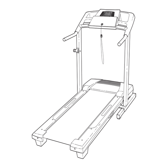
- Page 5 Locate the Reed Switch (10) and the Magnet (18) on the left side of the Pulley (17). Turn the Pulley until the 3 mm Magnet is aligned with the Reed Switch. Make sure that the gap between the Magnet and the Reed Switch is about 3 mm (1/8 in.).
-
Page 6: Important Precautions
IMPORTANT PRECAUTIONS WARNING: To reduce the risk of burns, fire, electric shock, or injury to persons, read the following important precautions and information before operating the treadmill. 1. It is the responsibility of the owner to ensure 11. If an extension cord is needed, use only a 3- that all users of this treadmill are adequately conductor, 1mm (14-gauge) cord that is no... - Page 7 19. When folding or moving the treadmill, make tenance and adjustment procedures de- sure that the storage latch is fully closed. scribed in this manual. Never remove the motor hood unless instructed to do so by an 20. Inspect and properly tighten all parts of the authorised service representative.
- Page 8 TROUBLESHOOTING Most treadmill problems can be solved by following the steps below. Find the symptom that applies, and follow the steps listed. If further assistance is needed, see the front cover of this manual. PROBLEM: The power does not turn on SOLUTION: a.
- Page 9 HOW TO FOLD AND MOVE THE TREADMILL HOW TO FOLD THE TREADMILL FOR STORAGE Before folding the treadmill, adjust the incline to the lowest position. If this is not done, the treadmill may be- come permanently damaged. Next, unplug the power cord. CAUTION: You must be able to safely lift 20 kg (45 lbs.) to raise, lower, or move the treadmill.
-
Page 10: Before You Begin
And when you’re not exercis- number of the treadmill is PETL37805.0. The serial ing, the unique X 800 treadmill can be folded up, re- number can be found on a decal attached to the tread- quiring less than half the floor space of other treadmills. -
Page 11: Assembly
ASSEMBLY Assembly requires two persons. Set the treadmill in a cleared area and remove all packing materials; do not dispose of the packing materials until assembly is completed. Note: The underside of the treadmill walking belt is coated with high-performance lubricant. During shipping, a small amount of lubricant may be transferred to the top of the walking belt or the shipping carton. - Page 12 The Distance/Pace display will Measure your heart rate if desired. show the total number of kilo- metres (or miles) that the See step 6 on page 13. walking belt has moved. Turn on the fan if desired. An “M,” for metric, or an “E,” See step 7 on page 13.
- Page 13 When only three seconds remain in the first period HOW TO USE A PRESET PROGRAM of the program, both the Current Period column and the column to the right will flash and a series Insert the key into the console. of tones will sound.
- Page 14 2. Attach a Wheel (66) to the base of the Uprights (69) with a Wheel Bolt (64) and a Wheel Nut (32) as shown. Do not overtighten the Wheel Bolt; the Wheel should turn freely. With the help of a second person, carefully tip the tread- mill onto its other side.
- Page 15 5. Touch the Right Handrail (72) to discharge any static. Slide the sleeve off the connector on the Upright Wire (42) as shown in the inset drawing. Next, press the end of the Upright Wire into the socket in the bottom of the Console Base (47).
- Page 16 The Speed display— If the displayed heart rate appears to be too high This display will show or too low, or if your heart rate is not displayed, lift the speed of the walk- your hands off the pulse sensor for a few sec- ing belt.
- Page 17 Change the incline of the treadmill as desired. HOW TO USE THE MANUAL MODE To change the incline of the treadmill, press the Insert the key into the console. Incline increase and de- crease buttons. Each See HOW TO TURN ON THE POWER on page time a button is pressed, the incline will change by 0.5%.
- Page 18 8. Orient the Latch Housing (29) so the large hole is on the indicated side. Attach the Latch Housing to the left Upright (69) with two 3/4” Screws (2). Remove the knob from the pin. Make sure that the col- lar and the spring are on the pin as shown.
-
Page 19: Operation And Adjustment
OPERATION AND ADJUSTMENT THE PRE-LUBRICATED WALKING BELT Your treadmill features a walking belt coated with high-performance lubricant. IMPORTANT: Never apply sili- cone spray or other substances to the walking belt or the walking platform. Such substances will deterio- rate the walking belt and cause excessive wear. HOW TO PLUG IN THE POWER CORD This product must be earthed. - Page 20 CONSOLE DIAGRAM Note: If there is a sheet of clear plastic Clip on the console, peel off the plastic. FEATURES OF THE CONSOLE HOW TO TURN ON THE POWER The console offers a selection of features designed to Plug in the power cord (see make your workouts at home more effective.
- Page 21 PART LIST—Model No. PETL37805.0 R0805A No. Qty. Description No. Qty. Description No. Qty. Description Hood 1” Tek Screw Outlet Assembly 3/4” Screw Ground Wire Power Cord Adaptor Motor Belt 5/32” Hex Key Belly Pan Motor Tension Bolt Upright Wire Belt Guide Latch Pin Assembly Console Belt Guide Screw...
-
Page 22: Ordering Replacement Parts
REMOVE THIS PART LIST/EXPLODED REMOVE THIS EXPLODED DRAWING AND PART DRAWING FROM THE MANUAL! LIST FROM THE MANUAL Save this EXPLODED DRAWING and PART LIST for future reference. Note: Specifications are subject to change without notice. For information about ordering replacement parts, see the back cover of the User’s Manual. - Page 23 EXPLODED DRAWING—Model No. PETL37805.0 R0805A...
Need help?
Do you have a question about the X 800 and is the answer not in the manual?
Questions and answers