Table of Contents

Related Manuals for Intel M10JNP2SB


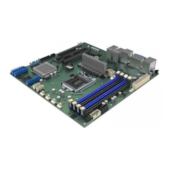
Summary of Contents for Intel M10JNP2SB
- Page 1 Intel® Server Board M10JNP2SB User Guide An overview of product features, functions, architecture, support specifications, and instructions for essential component installation. Rev 1.1 November 2019 Intel® Server Products and Solutions...
- Page 2 <Blank page>...
- Page 3 Intel® Server Board M10JNP2SB User Guide Document Revision History Date Revision Changes October 2019 First release. October 2019 1.01 Added product regulatory compliance table. November 2019 Chapter 3 - Added Supported processors...
- Page 4 Learn more at Intel.com, or from the OEM or retailer. You may not use or facilitate the use of this document in connection with any infringement or other legal analysis concerning Intel products described herein. You agree to grant Intel a non-exclusive, royalty-free license to any patent claim thereafter drafted which includes subject matter disclosed herein.
- Page 5 Intel recommends the following steps be taken when performing any procedures described within this document or while performing service to any computer system.
-
Page 6: Table Of Contents
Product Architecture Overview ..........................18 3. Processor Support ..............................19 Processor Features ................................ 20 3.1.1 Intel® Xeon® E-2100 processor family............Error! Bookmark not defined. 3.1.2 Intel® Xeon® E-2200 processor family............Error! Bookmark not defined. 4. Memory Support ............................... 21 Supported Memory ............................... 21 General Memory Population Rules ......................... - Page 7 Figure 3. Server board mounting holes ............................14 Figure 4. Component height restrictions ............................15 Figure 5. Major components and connectors 1 of 2 ........................16 Figure 6. Major components and connectors 2 of 2 ........................17 Figure 7. Intel® Server Board M10JNP2SB block diagram ....................... 18...
- Page 8 List of Tables Table 1. Intel® Server Board M10JNP2SB features/specifications ..................11 Table 2. Intel® Xeon® E-2200 processor family features list ....................19 Table 3. Intel® Xeon® E-2100 processor family features list ....................19 Table 4. DIMM population recommendations ..........................22 Table 5.
- Page 9 Intel® Server Board M10JNP2SB User Guide Table 11. SATADOM connector pin-out ............................30 Table 12. SGPIO connector pin-out ..............................30 Table 13. System fan connector pin-out............................31 Table 14. Processor fan connector pin-out ........................... 31 Table 15. Front panel header pin-out .............................. 31 Table 16.
-
Page 10: Introduction
Intel® Server Board M10JNP2SB User Guide Introduction This user guide provides a high level overview of the features, functions, and architecture of the Intel® Server Board M10JNP2SB. This document replaces the document previously known as the Technical Product Specification (TPS). -
Page 11: Server Board Overview
Intel® Server Board M10JNP2SB User Guide Server Board Overview The Intel® Server Board M10JNP2SB is a monolithic printed circuit board assembly with features for data center and office environments running multiple applications under a continuous work load. This server board is designed to support the Intel® Xeon® E 2200 processor family. - Page 12 • Slot 2: PCIe* 3.0 x8 slot (x8 electrical) • Slot 3: PCIe* 3.0 x16 slot (x8 electrical) Riser Card Support : Support for one PCIe 3.0 riser card on PCIe slot 3. (Sold separately. Optional Intel Accessory) Video • Integrated 2D video controller •...
-
Page 13: Server Board Component / Feature Identification
Intel® Server Board M10JNP2SB User Guide Server Board Component / Feature Identification Figure 2. Server board component / feature identification... -
Page 14: Server Board Mechanical Drawings
Intel® Server Board M10JNP2SB User Guide Server Board Mechanical Drawings Figure 3. Server board mounting holes... -
Page 15: Figure 4. Component Height Restrictions
Intel® Server Board M10JNP2SB User Guide Figure 4. Component height restrictions... -
Page 16: Figure 5. Major Components And Connectors 1 Of 2
Intel® Server Board M10JNP2SB User Guide Figure 5. Major components and connectors 1 of 2... -
Page 17: Figure 6. Major Components And Connectors 2 Of 2
Intel® Server Board M10JNP2SB User Guide Figure 6. Major components and connectors 2 of 2... -
Page 18: Product Architecture Overview
Intel® Server Board M10JNP2SB User Guide Product Architecture Overview The architecture of Intel® Server Board M10JNP2SB is developed around the integrated features and functions of the Intel® Xeon® E-2200 processor family, the Intel® C246 chipset (PCH), Intel® Ethernet Controller I210, and the ASPEED* AST2500 baseboard management controller (BMC). -
Page 19: Processor Support
Processor Support The server board includes one LGA1151 processor socket compatible with select models from the Intel® Xeon® E-2100 and Intel® Xeon® E-2200 processor families with a maximum Thermal Design Power (TDP) of 95 W. The Intel Server Board M10JNP2SB has been validated to support the following Intel processors: •... -
Page 20: Processor Features
GMM Scoring Accelerator • Intel® Processor Trace (Intel® PT) • High Definition Content Protection (HDCP) 2.2 Note: Feature availability may vary between processor SKUs. Refer to the Intel® Server Board M10JNP2SB Configuration Guide for a complete list of tested hardware. -
Page 21: Memory Support
The Intel® Xeon® E-2200 processor family includes an Integrated Memory Controller (IMC) capable of supporting two memory channels that can accommodate up to two DIMM slots per channel. On the Intel® Server Board M10JNP2SB, a total of four DIMM slots are provided as shown in Figure 9. -
Page 22: General Memory Population Rules
Memory RAS Features Each processor within the Intel® Xeon® E-2200 processor family has support for advanced memory RAS features as defined in Table 5. Table 5. Memory RAS features RAS Feature Description x8 Single Device Data Correction (SDDC) via static virtual... -
Page 23: Server Board I/O
The server board provides three PCI Express* (PCIe*) slots labeled: “PCIe#1”, “PCIe#2”, and “PCIe#3”. The PCIe* interface of the Intel® Server Board M10JNP2SB is fully compliant with the PCIe* Base Specification, Revision 3.0 supporting the following PCIe* bit rates: 3.0 (8.0 GT/s), 2.0 (5.0 GT/s), and 1.0 (2.5 GT/s). -
Page 24: One-Slot Pcie Riser Card Option (Ipc - Jnp1Uriser)
Slot # Description Slot-1 PCIe x8 elec, x16 mechanical Networking The Intel® Server Board M10JNP2SB includes five external RJ45 connectors providing support for the following features: • Four 1 Gb Network Interface Ethernet Ports • One dedicated 1 Gb server management port The following illustration shows the ports located on the back edge of the server board. -
Page 25: Usb
Amber No Link 5.3.1 MAC Address Definition The Intel® Server Board M10JNP2SB has the following MAC addresses assigned at the factory: • RJ45 Network Interface Ethernet Port 1 (base MAC address) • RJ45 Network Interface Ethernet Port 2 (base MAC address + 1) •... -
Page 26: Onboard Sata Support
Intel® Server Board M10JNP2SB User Guide Figure 14. Front panel USB 3.0 connector Onboard SATA Support The server board includes an AHCI SATA controller embedded in the chipset, providing eight 6 Gb/sec SATA ports with the following functionality: • Two white single port 9-pin connectors labeled “SATADOM-1/SATA-0” and “SATADOM-2/SATA-1”, providing support for SATA DOM (Disk on Module) storage devices. -
Page 27: Server Management
#4 on the back edge of the server board. This feature is disabled by default and can be enabled using the <F2> BIOS Setup Utility. Refer to the Intel® Server Board M10JNP2SB BIOS Setup Guide for more details. -
Page 28: Figure 16. Bmc Embedded Web Server User Interface
The web interface also provides a launch point keyboard, video, and mouse (KVM) and media redirection. For additional information, refer to the Intel® Server Board M10JNP2SB Integrated BMC Web Console User Guide. Figure 16. BMC embedded web server user interface... -
Page 29: On-Board Connector/Header Pin-Out Overview
Intel® Server Board M10JNP2SB User Guide On-Board Connector/Header Pin-Out Overview This chapter identifies the pin-outs for on-board connectors and headers on the Intel® Server Board M10JNP2SB that provide an interface for system options and features, onboard platform management, and other user accessible options or features. For more details on the location of the connectors in this chapter, see Figure 2. -
Page 30: Onboard Storage Connectors
Intel® Server Board M10JNP2SB User Guide Onboard Storage Connectors This section contains a functional overview and pin-out of each connector that the server board provides in support of several storage options. 7.2.1 SATA 6 Gbps Connectors The server board includes six blue 7-pin SATA connectors capable of transfer rates of up to 6 Gbps. Table 10 provides the pin-out for all six connectors. -
Page 31: Fan Connectors
Intel® Server Board M10JNP2SB User Guide Fan Connectors The server board supports a total of six fans: five in support of system cooling fans, and one in support of a processor fan. 7.3.1 System Fan Connectors The server board includes five 4-pin system fan connectors labeled SYS_FAN_# (1-5). Table 13 provides the pin-out for the connectors. -
Page 32: Dedicated Lan Activity Led Headers
Intel® Server Board M10JNP2SB User Guide Signal Name Pin# Pin# Signal Name P5V_USB_FP USB3_04_RXN USB3_01_RXN USB3_04_RXP USB3_01_RXP GROUND GROUND USB3_04_TXN USB3_01_TXN USB3_04_TXP USB3_01_TXP GROUND GROUND USB2_13_DN USB2_10_DN USB2_13_DP USB2_10_DP USB3_ID Dedicated LAN Activity LED Headers The server board includes two LED headers for Ethernet ports 3 and 4 which can be routed to a front panel that supports displaying LAN activity for 4 Ethernet controllers. -
Page 33: Power Supply Monitoring Interface (Psmi) Connector
Intel® Server Board M10JNP2SB User Guide Table 21. COM2 port pin-out Signal Signal KEY-Pin 7.6.2 Power Supply Monitoring Interface (PSMI) Connector The server board includes a PSMI connector for the BMC to monitor and communicate with the installed power supplies. The pin-out for this connector is shown in Table 22. -
Page 34: Reset And Recovery Jumpers
Intel® Server Board M10JNP2SB User Guide Reset and Recovery Jumpers The server board includes two jumper blocks which can be used to configure, protect, or recover specific features of the server board. Figure 17 identifies the location of each jumper block on the server board. Pin 1 of each jumper block can be identified by the arrowhead (▼) silkscreened on the server board next to the... -
Page 35: Bios Recovery Jumper
BIOS image to the UEFI shell, where a standard BIOS update can be performed. Refer to the BIOS update instructions that are included with the firmware update package downloaded from Intel’s download center website. This jumper is used when the BIOS has become corrupted and is non-functional, requiring a new BIOS image to be loaded on to the server board. -
Page 36: Server Board And Essential System Component Installation And Removal
2. Make sure the selected chassis has the necessary standoffs installed. These standoffs are usually metal and are gold in color. Intel recommends using metal standoffs with screws that will fasten the server board more securely in place. To confirm standoff placement, lay the server board inside the chassis and align the mounting holes of the server board to the standoffs inside the chassis. -
Page 37: Installing The Server Board
Intel® Server Board M10JNP2SB User Guide Installing the Server Board The instructions in this section describe the process of installing the server board in a chassis. The process described is for reference purposes only. Refer to the selected chassis documentation to determine if additional tools or steps are required. -
Page 38: Installing The Processor
Intel® Server Board M10JNP2SB User Guide Installing the Processor Required Tools and Supplies • Anti-static wrist strap and conductive foam pad (recommended) Figure 19. Removing the socket protection cap Remove the plastic socket protection cap. Note: The plastic socket protection cap should be saved and re-used should the processor need to be removed at anytime in the future. -
Page 39: Figure 21. Opening The Processor Load Plate
Intel® Server Board M10JNP2SB User Guide Figure 21. Opening the processor load plate Lift open the processor load plate. CAUTION: The pins inside the processor socket are extremely sensitive. Other than the processor, no object should make contact with the pins inside the processor socket. A damaged processor socket pin will render the socket inoperable, and will produce erroneous processor or other system errors if used. -
Page 40: Figure 23. Closing The Load Plate
Intel® Server Board M10JNP2SB User Guide Figure 23. Closing the load plate Carefully lower down the load plate over the processor. Figure 24. Closing the socket lever Lock down the load plate with the locking lever by lowering it down (see letter A) and sliding it under the... -
Page 41: Processor Heat Sink Installation
Intel® Server Board M10JNP2SB User Guide Processor Heat Sink Installation The instructions in this section describe the process of installing a processor heat sink. The process described is for reference purposes only. The selected heat sink to install on the server board may be different. -
Page 42: Heat Sink Removal
Intel® Server Board M10JNP2SB User Guide Heat Sink Removal The instructions in this section describe the process of removing a processor heat sink. The process described is for reference purposes only. The installed heat sink on the server board may be different. -
Page 43: Removing The Processor
Intel® Server Board M10JNP2SB User Guide Removing the Processor Required Tools and Supplies • Anti-static wrist strap and conductive foam pad (recommended) 4. Unlatch the processor load plate (see Section 9.2 step 2). 5. Lift open the load plate (see Section 9.2 step 3). -
Page 44: Connecting Sata Drives
Intel® Server Board M10JNP2SB User Guide Connecting SATA Drives This section describes the process of attaching SATA power and data cables (not included) when connecting SATA drives to the server board. Figure 31. Attaching SATA cables 1. Connect one end of the SATA data cable connector to the drive (see letter A). -
Page 45: Connecting System Fans
Intel® Server Board M10JNP2SB User Guide 9.11 Connecting System Fans The instructions in this section describe the process of attaching system fans to the server board. The process described is for reference purposes only. Refer to the selected chassis documentation to determine if additional tools or steps are required. -
Page 46: Disconnecting System Fans
Intel® Server Board M10JNP2SB User Guide 9.12 Disconnecting System Fans The instructions in this section describe the process of disconnecting system fans from the server board. The process described is for reference purposes only. Refer to the selected chassis documentation to determine if additional tools or steps are required. -
Page 47: Appendix A. Usage Tips
Intel® Server Board M10JNP2SB User Guide Appendix A. Usage Tips When installing add-in cards, find the appropriate slot for the add-in card and insert the card firmly. Do not force any add-in cards into any slots if they do not seat in place. It is recommended to try using another slot or a different card rather than damaging both the server board and the add-in card. -
Page 48: Appendix B. Getting Help
Server and chassis accessory parts list for ordering upgrades or spare parts • A searchable knowledgebase to search for product information throughout the support site If a solution cannot be found at Intel’s support site, send an email to Intel’s technical support center using the online form available at: http://www.intel.com/p/en_US/support/contactsupport Lastly, contact an Intel support representative using one of the support phone numbers available at http://www.intel.com/support/feedback.htm?group=server... -
Page 49: Appendix C. Post Code Errors
The POST code checkpoints are the largest set of checkpoints during the BIOS pre-boot process. In the Intel® Server Board M10JNP2SB the POST codes are visible on the lower right part of the screen during POST. The following table describes the type of checkpoints that may occur during the POST portion of the... -
Page 50: Table 26. Pei Phase
Intel® Server Board M10JNP2SB User Guide SEC Error Codes 0x0C – Reserved for future AMI SEC error codes 0x0D 0x0E Microcode not found 0x0F Microcode not found SEC Beep Codes None Table 26. PEI phase Status Description Code Progress Codes... - Page 51 Intel® Server Board M10JNP2SB User Guide Status Description Code 0x31 Memory Installed 0x32 CPU post-memory initialization is started 0x33 CPU post-memory initialization. Cache initialization CPU post-memory initialization. Application Processor(s) (AP) 0x34 initialization 0x35 CPU post-memory initialization. Boot Strap Processor (BSP) selection CPU post-memory initialization.
- Page 52 Intel® Server Board M10JNP2SB User Guide Status Description Code 0x5B Reset PPI is not available 0x5C – Reserved for future AMI error codes 0x5F S3 Resume Progress Codes 0xE0 S3 Resume is started (S3 Resume PPI is called by the DXE IPL)
- Page 53 Intel® Server Board M10JNP2SB User Guide Recovery Progress Codes 0xF0 Recovery condition triggered by firmware (Auto recovery) 0xF1 Recovery condition triggered by user (Forced recovery) 0xF2 Recovery process started 0xF3 Recovery firmware image is found 0xF4 Recovery firmware image is loaded 0xF5 –...
- Page 54 Intel® Server Board M10JNP2SB User Guide Status Description Code 0x66 CPU DXE initialization (CPU module specific) 0x67 CPU DXE initialization (CPU module specific) 0x68 PCI host bridge initialization 0x69 North Bridge DXE initialization is started 0x6A North Bridge DXE SMM initialization is started...
- Page 55 Intel® Server Board M10JNP2SB User Guide Status Description Code 0x9C USB Detect 0x9D USB Enable 0x9E -0x9F Reserved for future AMI codes 0xA0 IDE initialization is started 0xA1 IDE Reset 0xA2 IDE Detect 0xA3 IDE Enable 0xA4 SCSI initialization is started...
- Page 56 Intel® Server Board M10JNP2SB User Guide Status Description Code 0xD4 PCI resource allocation error. Out of Resources 0xD5 No Space for Legacy Option ROM 0xD6 No Console Output Devices are found 0xD7 No Console Input Devices are found 0xD8 Invalid password...
- Page 57 Intel® Server Board M10JNP2SB User Guide DXE Beep Codes # of Beeps Description Invalid password Some of the Architectural Protocols are not available No Console Output Devices are found No Console Input Devices are found Flash update is failed Reset protocol is not available...
-
Page 58: Appendix D. Additional References
Intel® Server Board M10JNP2SB User Guide Appendix D. Additional References Document Title Document Classification Intel® Server Board M10JNP2SB Configuration Guide Public Intel® Server Board M10JNP2SB BMC and EWS user guide Public Intel® Server Board M10JNP2SB Bios Setup Guide Public... -
Page 59: Appendix E. Safety Instructions
Intel® Server Board M10JNP2SB User Guide Appendix E. Safety Instructions WARNING: English (US) The power supply in this product contains no user-serviceable parts. There may be more than one supply in this product. Refer servicing only to qualified personnel. Do not attempt to modify or use the supplied AC power cord if it is not the exact type required. - Page 60 Intel® Server Board M10JNP2SB User Guide For proper cooling and airflow, always reinstall the chassis covers before turning on the system. Operating the system without the covers in place can damage system parts. To install the covers: 1. Check first to make sure you have not left loose tools or parts inside the system.
- Page 61 Intel® Server Board M10JNP2SB User Guide AVERTISSEMENT: Français Le bloc d'alimentation de ce produit ne contient aucune pièce pouvant être réparée par l'utilisateur. Ce produit peut contenir plus d'un bloc d'alimentation. Veuillez contacter un technicien qualifié en cas de problème.
- Page 62 Intel® Server Board M10JNP2SB User Guide Afin de permettre le refroidissement et l’aération du système, réinstallez toujours les panneaux du boîtier avant de mettre le système sous tension. Le fonctionnement du système en l’absence des panneaux risque d’endommager ses pièces. Pour installer les panneaux, procédez comme suit:...
- Page 63 Intel® Server Board M10JNP2SB User Guide WARNUNG: Deutsch Benutzer können am Netzgerät dieses Produkts keine Reparaturen vornehmen. Das Produkt enthält möglicherweise mehrere Netzgeräte. Wartungsarbeiten müssen von qualifizierten Technikern ausgeführt werden. Versuchen Sie nicht, das mitgelieferte Netzkabel zu ändern oder zu verwenden, wenn es sich nicht genau um den erforderlichen Typ handelt.
- Page 64 Intel® Server Board M10JNP2SB User Guide Zur ordnungsgemäßen Kühlung und Lüftung muß die Gehäuseabdeckung immer wieder vor dem Einschalten installiert werden. Ein Betrieb des Systems ohne angebrachte Abdeckung kann Ihrem System oder Teile darin beschädigen. Um die Abdeckung wieder anzubringen: 1.
- Page 65 Intel® Server Board M10JNP2SB User Guide AVVERTENZA: Italiano Rivolgersi ad un tecnico specializzato per la riparazione dei componenti dell'alimentazione di questo prodotto. È possibile che il prodotto disponga di più fonti di alimentazione. Non modificare o utilizzare il cavo di alimentazione in c.a. fornito dal produttore, se non corrisponde esattamente al tipo richiesto.
- Page 66 Intel® Server Board M10JNP2SB User Guide Per il giusto flusso dell’aria e raffreddamento del sistema, rimettere sempre le coperture del telaio prima di riaccendere il sistema. Operare il sistema senza le coperture al loro proprio posto potrebbe danneggiare i componenti del sistema. Per rimettere le coperture del telaio: 1.
- Page 67 Intel® Server Board M10JNP2SB User Guide ADVERTENCIAS: Español El usuario debe abstenerse de manipular los componentes de la fuente de alimentación de este producto, cuya reparación debe dejarse exclusivamente en manos de personal técnico especializado. Puede que este producto disponga de más de una fuente de alimentación.
- Page 68 Intel® Server Board M10JNP2SB User Guide Para obtener un enfriamiento y un flujo de aire adecuados, reinstale siempre las tapas del chasis antes de poner en marcha el sistema. Si pone en funcionamiento el sistema sin las tapas bien colocadas puede dañar los componentes del sistema. Para instalar las tapas: 1.
-
Page 69: Appendix F. Safety And Regulatory Certifications
Intel® Server Board M10JNP2SB User Guide Appendix F. Safety and Regulatory Certifications This product has been evaluated and certified as Information Technology Equipment (ITE), which may be installed in offices, schools, computer rooms, and similar commercial type locations. The suitability of this product for other product certification categories and/or environments (such as: medical, industrial, telecommunications, NEBS, residential, alarm systems, test equipment, etc.), other than an ITE application,... -
Page 70: Table 29. Product Regulatory Compliance Markings
Intel® Server Board M10JNP2SB User Guide Product Regulatory Compliance Markings Table 29. Product regulatory compliance markings Country/Origin Mark Logo Silkscreen Package Australia/New Zealand C-Tick CAN ICES-3(A) Canada Canada EMC Europe Yes (Logo Korea only) KC EMC R-R-CPU-Model Name & COO & Manufacture date Yes (Logo w/ info. -
Page 71: Table 30. Product Regulatory Compliance
Intel® Server Board M10JNP2SB User Guide WEEE Europe Company Name Intel Corporation or Intel Logo CA Perchlorate warning Product Regulatory Compliance Table 30. Product regulatory compliance Certification Countries Associated Comments List Austria, Italy, Belgium, Latvia, Bulgaria, Lithuania, Croatia, Luxembourg, Cyprus, Malta, Czechia,... -
Page 72: Appendix G. Statement Of Volatility
Intel® Server Board M10JNP2SB User Guide Appendix G. Statement Of Volatility This appendix describes the volatile and non-volatile components on the Intel® Server Board M10JNP2SB. It is not the intention of this document to include any components not directly mounted to the server board, including but not limited to: processors, memory, storage devices, or add-in cards. -
Page 73: Table 31. Server Board Components
Intel® Server Board M10JNP2SB User Guide Table 31. Server board components Part Volatility User Data Size Type Location Reference SDRAM BMC DDR4 Flash U12_IC BMC FW Flash U7_IC BIOS FW LAN1 U113 LAN1 FW Flash LAN2 U115 LAN2 FW Flash... -
Page 74: Glossary
Peripheral component interconnect, or CI local bus standard a.k.a. “Conventional PCI” Peripheral component interconnect express, an updated form of PCI offering better throughput and PCIe* error management Pre EFI initialization, a component of the Intel® Platform Innovation Framework for EFI architecture PEIM PEI module POST... - Page 75 Intel® Server Board M10JNP2SB User Guide SCSI Small computer system interface, a connetion normaly used for disks of various tyes SDDC Single device data correction Super I/o Server management mode Serial presence detect Thermal design power Trusted platform module Intel® TXT Intel®...
Need help?
Do you have a question about the M10JNP2SB and is the answer not in the manual?
Questions and answers