Table of Contents

Related Manuals for Intel S1200SPL


Summary of Contents for Intel S1200SPL
- Page 1 ® Intel Server Board S1200SP Product Family Technical Product Specification A document providing an overview of product features, functions, architecture, and support specifications Revision 1.7 February, 2018 Intel Server Products and Solutions...
- Page 2 Intel® Server Board S1200SP Family Technical Product Specification <This page is intentionally left blank.>...
- Page 4 Intel® Server Board S1200SP Family Technical Product Specification Revision History Date Revision Modifications Number Dec. 2015 Initial version March 2016 Added S1200SPO. September, 2016 Add TPM2.0 support; Update Enterprise M.2 support January , 2017 Added E3-1200 V6 processors support March, 2017 Added Intel®...
- Page 5 This document contains information on products, services and/or processes in development. All information provided here is subject to change without notice. Contact your Intel representative to obtain the latest TPS. The products and services described may contain defects or errors known as errata which may cause deviations from published specifications.
-
Page 6: Table Of Contents
Intel® Server Board S1200SP Family Technical Product Specification Table of Contents Introduction .................................. 1 Chapter Outline .................................... 1 Server Board Use Disclaimer ..............................1 Overview ..................................2 Intel ® Server Board S1200SP Family Feature Set ......................2 Server Board Layout ................................... 4 2.2.1... - Page 7 Intel® Server Board S1200SP Family Technical Product Specification Trusted Platform Module (TPM) Support ........................34 4.2.1 TPM security BIOS ................................34 4.2.2 Physical Presence ................................35 4.2.3 TPM Security Setup Options ............................35 Intel ® Trusted Execution Technology ..........................37 Intel ®...
- Page 8 Intel® Server Board S1200SP Family Technical Product Specification 6.11.15 Embedded Platform Debug ............................63 6.11.16 Data Center Management Interface (DCMI) ....................... 65 6.11.17 Lightweight Directory Access Protocol (LDAP) ....................65 Advanced Management Feature Support (RMM4) .................... 66 Dedicated Management Port ............................... 66 Keyboard, Video, and Mouse (KVM) Redirection ......................
- Page 9 Intel® Server Board S1200SP Family Technical Product Specification Fan Headers ....................................83 Jumper Blocks ................................85 BIOS Default Jumper (J4C1) ..............................86 BIOS Recovery Jumper (J7B1) ............................. 86 Password Clear Jumper (J1F4) ............................87 Management Engine (ME) Firmware Force Update Jumper (J1F1) ..............88 BMC Force Update Jumper (J4B1) .............................
- Page 10 Intel® Server Board S1200SP Family Technical Product Specification Glossary ................................... 130 Reference Documents ..............................133...
- Page 11 ® Server Board S1200SP – Major Connector Pin-1 Locations ................ 10 Figure 8. Intel® Server Board S1200SP – Major Connector Pin-1 Locations (continued) ..........11 Figure 9. Intel® Server Board S1200SP – Primary Side Keepout Zone ................. 12 Figure 10. Intel® Server Board S1200SP – Second Side Keepout Zone ................13 Figure 11.
- Page 12 Table 17. Diagnostic Data ................................64 Table 18. Additional Diagnostics on Error ..........................65 Table 19. Intel® Remote Management Module 4 (RMM4) Options ..................66 Table 20. Board Connector Matrix ............................. 70 Table 21. Main Power Connector Pin-out (J9H1) ........................71 Table 22.
- Page 13 Intel® Server Board S1200SP Family Technical Product Specification Table 53. Minimum Load Ratings............................... 96 Table 54. Voltage Regulation Limits ............................97 Table 55. Transient Load Requirements ........................... 97 Table 56. Capacitive Loading Conditions ..........................98 Table 57. Ripples and Noise ............................... 99 Table 58.
- Page 14 Intel® Server Board S1200SP Family Technical Product Specification < This page intentionally left blank. >...
-
Page 15: Introduction
Design-level information related to specific server board components and subsystems can be obtained by ordering External Product Specifications (EPS) or External Design Specifications (EDS) related to this server generation. EPS and EDS documents are made available under NDA with Intel® and must be ordered through your local Intel® representative. See the section for a list of available documents. -
Page 16: Overview
The Intel ® Server Board S1200SP product family consist of S1200SPS and S1200SPL. The server boards are monolithic printed circuit boards (PCBs) with features designed to support the pedestal or rack server markets. These server boards are designed to support the Intel ®... -
Page 17: Table 2. Limiting Conditions Of Pcie* Card Form Factor
Note: The server board S1200SPL and S1200SPS support full height full length PCIe* cards. See the following table for the limitations when the server boards is installed in server chassis P4000XXSFDR. Table 2. Limiting Conditions of PCIe* Card Form Factor... -
Page 18: Server Board Layout
Intel® Server Board S1200SP Family Technical Product Specification 2.2 Server Board Layout Figure 1. Intel ® Server Board S1200SP Layout (S1200SPL) -
Page 19: Server Board Connector And Component Layout
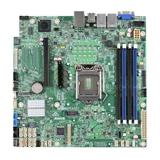
Intel® Server Board S1200SP Family Technical Product Specification 2.2.1 Server Board Connector and Component Layout Each connector and major component is identified in the figure below. Figure 2. Intel Server Board S1200SPL Layout ®... -
Page 20: Figure 3. Intel Server Board S1200Sps Layout
Intel® Server Board S1200SP Family Technical Product Specification Figure 3. Intel ® Server Board S1200SPS Layout... -
Page 21: Figure 4. Intel Server Board S1200Spo Layout
Intel® Server Board S1200SP Family Technical Product Specification Figure 4. Intel ® Server Board S1200SPO Layout... -
Page 22: Server Board Mechanical Drawings
Intel® Server Board S1200SP Family Technical Product Specification 2.2.2 Server Board Mechanical Drawings Figure 5. Intel ® Server Board S1200SP – Mounting Hole Locations... -
Page 23: Figure 6. Intel® Server Board S1200Sp - Mounting Hole Locations (Continued)
Intel® Server Board S1200SP Family Technical Product Specification Figure 6. Intel® Server Board S1200SP – Mounting Hole Locations (continued) -
Page 24: Figure 7. Intel Server Board S1200Sp - Major Connector Pin-1 Locations
Intel® Server Board S1200SP Family Technical Product Specification Figure 7. Intel Server Board S1200SP – Major Connector Pin-1 Locations ®... -
Page 25: Figure 8. Intel® Server Board S1200Sp - Major Connector Pin-1 Locations (Continued)
Intel® Server Board S1200SP Family Technical Product Specification Figure 8. Intel® Server Board S1200SP – Major Connector Pin-1 Locations (continued) -
Page 26: Figure 9. Intel® Server Board S1200Sp - Primary Side Keepout Zone
Intel® Server Board S1200SP Family Technical Product Specification Figure 9. Intel® Server Board S1200SP – Primary Side Keepout Zone... -
Page 27: Figure 10. Intel® Server Board S1200Sp - Second Side Keepout Zone
Intel® Server Board S1200SP Family Technical Product Specification Figure 10. Intel® Server Board S1200SP – Second Side Keepout Zone... -
Page 28: Server Board Rear I/O Layout
Intel® Server Board S1200SP Family Technical Product Specification 2.2.3 Server Board Rear I/O Layout The following drawing shows the layout of the rear I/O components for the server boards. Figure 11. Intel ® Server Board S1200SPL Rear I/O Layout Figure 12. Intel Server Board S1200SPS Rear I/O Layout ®... -
Page 29: Functional Architecture
The architecture and design of the Intel ® Server Board S1200SP is based on the Intel ® C230 series chipset. The chipset is designed for systems based on the Intel Xeon processor in an LGA 1151 Socket H4 package. ® ®... -
Page 30: Intel
Intel® Server Board S1200SP Family Technical Product Specification ® ® 3.1.1 Intel Xeon processor E3-1200 V5 and V6 Product Family Intel Xeon processor E3-1200 V5 and V6 product family highly integrated solution variant is composed of ® ® quad processor cores: LGA 1151 socket package with 8 GT/s •... -
Page 31: Integrated Memory Controller (Imc) And Memory Subsystem
Intel® SGX is a system of architectural enhancement defined to help protect application integrity and confidentiality of data, and to withstand SW and certain HW attacks. Intel® SGX will allow the application developer to provide application security without dependency on the correctness of the OS, VMM, BIOS, drivers, etc. -
Page 32: Supported Memory
1866, 2133 DRx8 16GB 2400 (only Intel E3-1200 V6) 2400 (only Intel E3-1200 V6) Note: Note: In case of using 2400 MHz memory modules with Intel E3-1200 v5 processor, the speed of the memory will be reduced to 2133 MHz. - Page 33 When only one memory channel is populated, the memory runs in Single Channel mode, with no • interleaving. When using one or two memory modules, populate the farthest slot in the channel. On Intel® Server Board • S1200SP, the farthest slot in the channels are A2 and B2 with blue connectors.
-
Page 34: Table 5. Intel Server Board S1200Sp Dimm Maximum Configuration
Intel® Server Board S1200SP Family Technical Product Specification Figure 15. Intel Server Board S1200SP DIMM Slot Layout ® Table 5. Intel Server Board S1200SP DIMM Maximum Configuration ® Max Memory Possible 4Gb DRAM Technology 8Gb DRAM Technology Single Rank UDIMM... -
Page 35: Memory Ras Features
Intel® Server Board S1200SP Family Technical Product Specification Processor microcode Memory Mapped I/O (MMIO) Manageability Engine (ME) BIOS flash 3.3.2 Memory RAS Features For Intel Server Board S1200SP product family, the form of Memory RAS provided is Error Correction Code ®... -
Page 36: Processor Integrated I/O Module (Iio)
Intel Integrated RAID Option The Intel ® Server Board S1200SPL and S1200SPO provide a SAS/ROC Mezzanine slot (J4J1) to a high density 80-pin connector labeled SAS_MOD for the installation of an optional Intel ® Integrated RAID Module. Features of this option include:... -
Page 37: Optional I/O Module Support
Optional I/O Module Support To broaden the standard on board feature set, the Intel® Server Board S1200SPO provides support for one of several available IO Module options. The I/O Module attaches to a high density 80-pin connectors on the server board (J1C1) labeled I/O_MOD and is supported by up to x8 PCIe Gen 3 signals from IIO module of the processor. -
Page 38: Digital Media Interface (Dmi)
KVM/Serial Over LAN (SOL) Function • 3.4.1 Digital Media Interface (DMI) Digital Media Interface (DMI) is the chip-to-chip connection between the processor and the Intel ® C230 series chipset. This high-speed interface integrates advanced priority-based servicing allowing for concurrent traffic and true isochronous transfer capabilities. - Page 39 ® ® AHCI (see above for details on AHCI) and integrated RAID functionality. The industry-leading RAID capability provides high-performance RAID 0, 1, 5, and 10 functionality on up to 8 SATA ports of the Intel ® C230 series chipset. RSTe RAID support is provided to allow multiple RAID levels to be combined on a single set of hard drives, such as RAID 0 and RAID 1 on two disks.
-
Page 40: Low Pin Count (Lpc) Interface
USB 2.0 ports and up to six USB 3.0 ports. This controller allows data transfers of up to 5Gb/s. The controller supports SuperSpeed (SS), high-speed (HS), full-speed (FS), and low speed (LS) traffic on the bus. Figure 16. Intel® Server Board S1200SP Series USB Mapping Diagram 3.4.6.1 Native USB Support During the power-on self-test (POST), the BIOS initializes and configures the USB subsystem. -
Page 41: Gigabit Ethernet Controller
Ethernet Controller I210 is single, compact, low-power ® components that offer a fully-integrated Gigabit Ethernet Media Access Control (MAC) and Physical Layer (PHY) port. The Intel Ethernet Controller I210 uses the PCI Express* architecture from the Intel C230 series ® ®... -
Page 42: Serial Ports
3.4.7.1 MAC Address Definition Intel ® Server Board S1200SPL and S1200SPO have the following MAC addresses assigned to them at the factory: NIC 1 MAC address (for OS usage) • NIC 2 MAC address = NIC 1 MAC address + 1 (for OS usage) •... -
Page 43: System Management Bus (Smbus* 2.0)
® 3.4.11 Intel Virtualization Technology for Direct I/O (Intel VT-d) The Intel ® C230 series chipset provides hardware support for implementation of Intel ® Virtualization Technology with Directed I/O (Intel ® VT-d). Intel ® VT-d Technology consists of technology components that support the virtualization of platforms based on Intel ®... -
Page 44: Super I/O Controller
Intel® Server Board S1200SP Family Technical Product Specification NAND/Memory interface • Sixteen mailbox registers for communication between the BMC and host • LPC ROM interface • BMC watchdog timer capability • SD/MMC card controller with DMA support • LED support with programmable blink rate controls on GPIOs •... -
Page 45: Remote Keyboard, Video, Mouse, And Storage (Kvms)
Intel® Server Board S1200SP Family Technical Product Specification 3.5.2 Remote Keyboard, Video, Mouse, and Storage (KVMS) The Integrated BMC contains a remote KVMS subsystem with the following features: USB 2.0 interface for Keyboard, Mouse and Remote storage such as CD/DVD ROM and floppy •... - Page 46 I/O section of the server board. On Intel® Server Board S1200SPL, the display port is supported from the processor. A display port to VGA convertor and a VGA mux are implemented to enable VGA output from processor graphics. Users can set “Primary Display”...
-
Page 47: System Security
Intel® Server Board S1200SP Family Technical Product Specification System Security 4.1 BIOS Password Protection The BIOS uses passwords to prevent unauthorized tampering with the server setup. Passwords can restrict entry to the BIOS Setup, restrict use of the Boot Popup menu, and suppress automatic USB device reordering. -
Page 48: Trusted Platform Module (Tpm) Support
Intel® Server Board S1200SP Family Technical Product Specification if enabled, when a new USB boot device is attached to the system. A User is restricted from booting in anything other than the Boot Order defined in the Setup by an Administrator. -
Page 49: Physical Presence
TPM ownership security key was lost. 4.2.3.1 Security Screen To enter the BIOS Setup, press the <F2> function key during boot time when the OEM or Intel ® logo displays. The following message displays on the diagnostics screen and under the Quiet Boot logo screen: Press <F2>... -
Page 50: Figure 17. Setup Utility - Tpm Configuration Screen
Intel® Server Board S1200SP Family Technical Product Specification To access this screen from the Main screen, select the Security option. Server Main Advanced Security Boot Options Boot Manager Management Error! Reference source <Installed/Not Installed> ound. Error! Reference source <Installed/Not Installed>... -
Page 51: Intel
TXT), which is a robust security environment. Designed to help protect against software-based attacks, Intel ® Trusted Execution Technology integrates new security features and capabilities into the processor, chipset, and other platform components. When used in conjunction with Intel ® Virtualization Technology, Intel ®... -
Page 52: Intel Technology Support
Region Reporting) structure in the DMAR. Each RMRR has a Device Scope listing the devices in the system that can cause a DMA request to the region. For more information on the DMAR table and the DRHD entry format, refer to the Intel ®... -
Page 53: Intel Intelligent Power Node Manager
Ability to monitor server inlet temperatures to enable greater rack utilization in areas with adequate cooling The requirements listed above are those that are addressed by the Intel ® C230 series chipset Management Engine (ME) and Intel ®... - Page 54 Intel® Server Board S1200SP Family Technical Product Specification Platform Power Monitoring and Limiting: The ME/NM monitors platform power consumption and holds • average power over duration. It can be queried to return actual power at any given instance. The power limiting capability is to allow external management software to address key IT issues by setting a power budget for each server.
-
Page 55: Hardware Requirements
Intel® Server Board S1200SP Family Technical Product Specification 5.3.1 Hardware Requirements NM is supported only on platforms that have the NM FW functionality loaded and enabled on the Management Engine (ME) in the SSB and that have a BMC present to support the external LAN interface to the ME. NM power limiting feature requires a means for the ME to monitor input power consumption for the platform. -
Page 56: Platform Management Functional Overview
Intel® Server Board S1200SP Family Technical Product Specification Platform Management Functional Overview Platform management functionality is supported by several hardware and software components integrated on the server board that work together to control system functions, monitor and report system health, and control various thermal and performance features in order to maintain (when possible) server functionality in the event of component failure and/or environmentally stressed conditions. -
Page 57: Non-Ipmi Features
Intel® Server Board S1200SP Family Technical Product Specification 6.1.2 Non-IPMI Features The BMC supports the following non-IPMI features. This list does not preclude support for future enhancements or additions. In-circuit BMC firmware update • Fault resilient booting (FRB): FRB2 is supported by the watchdog timer functionality. -
Page 58: Advanced Configuration And Power Interface (Acpi)
Intel® Server Board S1200SP Family Technical Product Specification Feature Basic* Advanced** Hot-Swap Fan Support Acoustic Management Diagnostic Beep Code Support Power State Retention ARP/DHCP Support PECI Thermal Management Support E-mail Alerting Embedded Web Server SSH Support Integrated KVM Integrated Remote Media Redirection... -
Page 59: Power Control Sources
6.5 BMC Watchdog The BMC FW is increasingly called upon to perform system functions that are time-critical in that failure to provide these functions in a timely manner can result in system or component damage. Intel ® server board S1200SP introduces a BMC watchdog feature to provide a safe-guard against this scenario by providing an automatic recovery mechanism. -
Page 60: Fault Resilient Booting (Frb)
Intel® Server Board S1200SP Family Technical Product Specification Low or out-of-memory condition – The platform management subsystem will reset itself upon detection • of this condition. The BMC watchdog feature only allows up to three resets of the BMC CPU (such as HW reset) or entire FW stack (such as a SW reset) before giving up and remaining in the uBOOT code. -
Page 61: Sensor Monitoring
SEL beyond the allocated space will overwrite the oldest entries in the SEL, while setting the overflow flag. Events logged to the SEL can be viewed using Intel’s SELVIEW utility, Embedded Web Server, and Active System Console. -
Page 62: Thermal And Acoustic Management
Intel® Server Board S1200SP Family Technical Product Specification separate configurable fan control policy. A fan domain can have a set of temperature and fan sensors associated with it. These are used to determine the current fan domain state. A fan domain has three states: sleep, nominal, and boost. The sleep and boost states have fixed (but configurable through OEM SDRs) fan speeds associated with them. -
Page 63: Auto Profiles
Intel® Server Board S1200SP Family Technical Product Specification I/O module Temperature Sensor (With option installed) • Intel® ROC Module (With option installed) • Riser Card Temperature Sensors • Intel® Xeon Phi™ coprocessor (With option installed) • Notes: For fan speed control in Intel® chassis... -
Page 64: Memory Thermal Throttling
DRAM temperature in between actual reads of the TSODs. Hybrid CLTTT shall be used on all Intel® Server Systems supporting the Intel® Xeon® processor E3-1200 V5 and V6 product family that have DIMMs with thermal sensors. Therefore, the terms Dynamic-CLTT and Static-CLTT are really referring to this ‘hybrid’... -
Page 65: User Model
Intel® Server Board S1200SP Family Technical Product Specification Channel ID Interface Supports Sessions (Provided by the Intel ® Dedicated Server Management NIC) Reserved Secondary IPMB 8 – 0Dh Reserved – Self – SMS/Receive Message Queue Notes: Optional hardware supported by the server system. -
Page 66: Lan Interface
Intel® Server Board S1200SP Family Technical Product Specification 6.11.3 LAN Interface The BMC implements both the IPMI 1.5 and IPMI 2.0 messaging models. These provide out-of-band local area network (LAN) communication between the BMC and the network. See the Intelligent Platform Management Interface Specification Second Generation v2.0 for details about the IPMI-over-LAN protocol. - Page 67 IP Address: Static • All users disabled • IPMI-enabled network interfaces may not be placed on the same subnet. This includes the Intel Dedicated ® Server Management NIC and either of the BMC’s embedded network interfaces. Host-BMC communication over the same physical LAN connection – also known as loopback – is not supported.
- Page 68 Intel® Server Board S1200SP Family Technical Product Specification 6.11.3.3 IPV6 Support In addition to IPv4, the server board supports IPv6 for manageability channels. Configuration of IPv6 is provided by extensions to the IPMI Set and Get LAN Configuration Parameters commands as well as through a Web Console IPv6 configuration web page.
- Page 69 Intel® Server Board S1200SP Family Technical Product Specification 6.11.3.5 BMC IP Address Configuration Enabling the BMC’s network interfaces requires using the Set LAN Configuration Parameter command to configure LAN configuration parameter 4, IP Address Source. The BMC supports this parameter as follows: 1h, static address (manually configured): Supported on all management NICs.
- Page 70 Intel® Server Board S1200SP Family Technical Product Specification If a command is issued to set the default gateway IP address before the BMC’s IP address and subnet mask are set, the default gateway IP address is not updated and the BMC returns 0xCC.
-
Page 71: Address Resolution Protocol (Arp)
Intel® Server Board S1200SP Family Technical Product Specification All Block write requests are updated into a local Memory byte array. When Byte 2 is set to Update is • Complete, the Local Memory is committed to the NV Storage. Local Memory is reset to NULL after changes are committed. -
Page 72: Secure Shell (Ssh)
Intel® Server Board S1200SP Family Technical Product Specification Parameter 25 (VLAN Destination Address) of the Set LAN Config Parameters IPMI command is not supported and returns a completion code of 0x80 (parameter not supported) for any read/write of parameter 25. -
Page 73: Lan Alerting
Intel® Server Board S1200SP Family Technical Product Specification Table 16. Factory Configured PEF Table Entries Event Filter Offset Mask Events Number Non-critical, critical and non- Temperature sensor out of recoverable range Non-critical, critical and non- Voltage sensor out of range... -
Page 74: Sm-Clp (Sm-Clp Lite)
Intel® Server Board S1200SP Family Technical Product Specification because the destination types and alerts may vary by user. Each entry in the alert policy table contains four bytes for a maximum table size of 80 bytes. 6.11.11.1 E-mail Alerting The Embedded Email Alerting feature allows the user to receive e-mails alerts indicating issues with the server. - Page 75 Intel® Server Board S1200SP Family Technical Product Specification two concurrent web sessions from up to two different users is supported. The embedded web user interface supports the following client web browsers: Microsoft Internet Explorer 9.0* • Microsoft Internet Explorer 10.0* •...
-
Page 76: Virtual Front Panel
Intel® Server Board S1200SP Family Technical Product Specification Ability to get and set Node Manager (NM) power policies. • Display of power consumed by the server. • Ability to view and configure VLAN settings. • Warn user the reconfiguration of IP address will cause disconnect. -
Page 77: Embedded Platform Debug
The data can be analyzed by Intel® for failure analysis and possibly provided to the power supply vendor as well. The BMC gets this data from the power supplied from the PMBus* manufacturer-specific commands. -
Page 78: Table 17. Diagnostic Data
Intel FW developers deem useful in addition to the data specified in this document. File #2 can be viewed by Intel partners who have signed an NDA with Intel and its contents are restricted to specific data items specified in this with the exception of the BMC syslog messages and power supply black box data. -
Page 79: Data Center Management Interface (Dcmi)
Internet Portal Data Center (IPDC) customers. It is expected to become a requirement for server platforms which are targeted for IPDCs. DCMI is an IPMI-based standard that builds upon a set of required IPMI standard commands by adding a set of DCMI-specific IPMI OEM commands. Intel ®... -
Page 80: Advanced Management Feature Support (Rmm4)
Module 4 Lite redirection When the BMC FW initializes, it attempts to access the Intel® RMM4 Lite. If the attempt to access the Intel® RMM4 Lite is successful, then the BMC activates the advanced features. On the server board Intel ®... -
Page 81: Remote Console
Intel® Server Board S1200SP Family Technical Product Specification This feature allows a user to interactively use the keyboard, video, and mouse functions of the remote server as if the user were physically at the managed server. KVM redirection console supports the following keyboard layouts: English, Dutch, French, German, Italian, Russian, and Spanish. -
Page 82: Performance
Intel® Server Board S1200SP Family Technical Product Specification 7.2.2 Performance The remote display accurately represents the local display. The feature adapts to changes to the video resolution of the local display and continues to work smoothly when the system transitions from graphics to text or vice versa. -
Page 83: Availability
Intel® Server Board S1200SP Family Technical Product Specification device appears just like a local device to the server, allowing system administrators or users to install software (including operating systems), copy files, update BIOS, and so on, or boot the server from this device. -
Page 84: On-Board Connector/Header Overview
Intel® Server Board S1200SP Family Technical Product Specification 8 On-board Connector/Header Overview The following section provides detailed information regarding all connectors, headers, and jumpers on the server boards. 8.1 Board Connector Information The following table lists all connector types available on the board and the corresponding preference designators printed on the silkscreen. -
Page 85: Power Connectors
Intel® Server Board S1200SP Family Technical Product Specification Connector Quantity Reference Designators Connector Type Pin Count IPMB J1G2 Header J4B1 (Force Integrated BMC update), J1F4 (Password Clear), Configuration jumpers J7B1 (BIOS Recovery), Jumper J4C1 (Reset BIOS Configuration) J1F1 (ME Firmware Update) -
Page 86: System Management Headers
RMM4 Lite connector and a stacked connector that includes a USB 3.0 and a dedicated 1GbE RJ45 Management Port. The management port is active with or without the RMM4 Lite key installed. The S1200SPS board does not support Intel RMM4. -
Page 87: Tpm Connector
SPI_RMM4_LITE_CLK SPI_RMM4_LITE_DO SPI_RMM4_LITE_CS_N 8.3.2 TPM Connector The Intel® Server Board S1200SPL and S1200SPO support TPM 2.0 module AXXTPMSPE6. The S1200SPS server board does not support TPM 2.0 module. Table 27. TPM Connector Pin-out (J8K1) Signal Name Signal Name Key Pin LPC_LAD<1>... -
Page 88: Chassis Intrusion Header
8.3.6 SATA SGPIO Header Two SATA SGPIO 5 pin headers are implemented on the Intel® Server Board S1200SPL and S1200SPO: one is for Port0-3 (White) and the other is for Port4-7 (Black). Table 31. SATA SGPIO Header Pin-out (J2K5, J2K6) -
Page 89: Power/Sleep Button And Led Support
Intel® Server Board S1200SP Family Technical Product Specification Hard Drive Activity LEDs • System Status LED • System ID LED • The following table provides the pin-out for this connector: Table 33. Front Panel 24-pin Connector Pin-out (J9E1) Signal Name... -
Page 90: Nmi Button Support
Intel® Server Board S1200SP Family Technical Product Specification 8.4.4 NMI Button Support When the NMI button is pressed, it puts the server in a halt state and causes the BMC to issue a non-maskable interrupt (NMI). This can be useful when performing diagnostics for a given issue where a memory download is necessary to help determine the cause of the problem. -
Page 91: Display Port Connector
8.5.3 SATA Connectors The Intel® Server Board S1200SPL and S1200SPO provide up to eight on-board SATA connectors, while the Intel® Server Board S1200SPS provides six SATA connectors: SATA-0 (J2K4), SATA-1 (J2K2), SATA-2 (J2K3), SATA-3 (J2K1), SATA-4 (J1K5), SATA-5 (J1K2), SATA-6 (J1K4), and SATA-7 (J1K1). -
Page 92: Sata Connector (J2G1)
M.2 SATA Connector (J2G1) The Intel® Server Board S1200SPL and S1200SPO support one 22x42mm enterprise M.2 SATA SSD. In order to use M.2 device, a SATA cable need to be connected between any of the SATA connectors (SATA-0 to SATA- 7, recommend SATA-7 for better cable routing) and the SATA connector (black) next to the jumpers. -
Page 93: Serial Port Connector
Intel® Server Board S1200SP Family Technical Product Specification Table 39. M.2 SATA Connector Pinout 8.5.5 Serial Port Connector The server board provides one internal 9-pin Serial header. The following tables define the pin-out. Table 40. Internal 9-pin Serial Header Pin-out (J9A1) -
Page 94: Usb Connector
The Server Board S1200SP Series provide: One 2x5 pin USB 2.0 header, providing front panel support for two USB ports respectively One 2x10 pin USB 3.0 header on S1200SPL and S1200SPO, providing front panel support for two USB 3.0 ports respectively (P4000XXSFDR chassis) 2x USB 2.0 ports at the back of the board... -
Page 95: I/O Module Connector
Intel® Server Board S1200SP Family Technical Product Specification 8.5.7 I/O Module Connector The following table details the pin-out definition of the I/O Module connector which is available only on the Intel® Server Board S1200SPO. Table 45. I/O Module Connector Pin-out (J1C1) -
Page 96: Sas/Roc Module Connector
Intel® Server Board S1200SP Family Technical Product Specification 8.5.8 SAS/ROC Module Connector The Intel® Server Board S1200SPL and S1200SPO support Intel® Integrated RAID Module (known as SAS/ROC module). The SAS/ROC module can be installed to the server board as shown below. Figure 22. Installing Intel Integrated RAID Module ®... -
Page 97: Nic Connector
Intel® Server Board S1200SP Family Technical Product Specification Signal Name Signal Name PCIe Gen3 Rp [4] PCIe Gen3 Tn [3] PCIe Gen3 Tp [3] PCIe Gen3 Rn [3] PCIe Gen3 Rp [3] PCIe Gen3 Tn [2] PCIe Gen3 Tp [2]... -
Page 98: Figure 22. Fan Headers On The Server Borad
Note: Intel Corporation server boards support peripheral components and can contain a number of high- density VLSI and power delivery components that need adequate airflow to cool. Intel’s own chassis are designed and tested to meet the intended thermal requirements of these components when the fully integrated system is used together. -
Page 99: Jumper Blocks
For safety purposes, the power cord should be disconnected from a system before removing any system components or moving any of the on-board jumper blocks. System Update and Recovery files are included in the System Update Packages (SUP) posted to Intel’s website. -
Page 100: Bios Default Jumper (J4C1)
This jumper is NOT used when the BIOS is operating normally and you need to update the BIOS from one version to another. The following steps demonstrate the BIOS recovery process: 1. After downloading the latest System Update Package (SUP) from the Intel ® website, copy the following files to the root directory of a USB media device: IPMI.EFI... -
Page 101: Password Clear Jumper (J1F4)
Intel® Server Board S1200SP Family Technical Product Specification IFlash32.EFI RML.ROM ######.CAP (where #### = BIOS revision number, any cap file is suitable to make the recovery) STARTUP.NSH 2. Power OFF the system. 3. Locate the BIOS Recovery Jumper on the server board and move the jumper block from pins 1-2 (default) to pins 2-3 (recovery setting). -
Page 102: Management Engine (Me) Firmware Force Update Jumper (J1F1)
This jumper should only be used if the ME firmware has gotten corrupted and requires re-installation. The following procedure should be followed. Note: System Update and Recovery files are included in the System Update Packages (SUP) posted to Intel’s website. - Page 103 Intel® Server Board S1200SP Family Technical Product Specification Note: System Fans will boost and the BIOS Error Manager should report an 84F3 error code (Baseboard Management Controller in update mode). 5. Boot to the EFI shell and update the BMC firmware using BMC####.NSH (where #### is the version number of the BMC).
-
Page 104: Intel Light Guided Diagnostics
Intel® Server Board S1200SP Family Technical Product Specification Intel ® Light Guided Diagnostics The server board includes several on-board LED indicators to aid troubleshooting various board level faults. The following figure shows the location for each: Figure 25. On-Board LED Placement 10.1... -
Page 105: Table 49. System Status Led State Definitions
Intel® Server Board S1200SP Family Technical Product Specification When the server is powered down (transitions to the DC-off state or S5), the BMC is still on standby power and retains the sensor and front panel status LED state established before the power-down event. -
Page 106: Bmc Boot/Reset Status Led Indicators
Intel® Server Board S1200SP Family Technical Product Specification Color State Criticality Description Amber ~1 Hz blink Non-critical - Non-fatal alarm – system is likely to fail: System is Critical threshold crossed – Voltage, temperature (including HSBP operating in a temp), input power to power supply, output current for main power degraded state rail from power supply and PROCHOT (Therm Ctrl) sensors. -
Page 107: Post Code Diagnostic Leds
Intel® Server Board S1200SP Family Technical Product Specification Table 51. BMC Boot/Reset Status LED Indicators BMC Boot/Reset State ID LED Status Comment BMC/Video memory test failed Solid Blue Solid Nonrecoverable condition. Contact your Intel ® Amber representative for information on replacing this motherboard. -
Page 108: Environmental Limits Specification
Intel Corporation server boards contain a number of high-density VLSI and power delivery components that need adequate airflow to cool. Intel ensures through its own chassis development and testing that when Intel server building blocks are used together, the fully integrated system will meet the intended thermal requirements of these components. -
Page 109: Mtbf
Intel Corporation cannot be held responsible, if components fail or the server board does not operate correctly when used outside any of their published operating or non-operating limits. -
Page 110: Server Board Power Distribution
The power supply data provided in this section is for reference purposes only. It reflects Intel’s own DC power out requirements for a CRPS 460W power supply as used in an Intel designed 4U server chassis P4000XXSFDR. -
Page 111: Standby Output
Intel® Server Board S1200SP Family Technical Product Specification Notes: 12Vstby must provide 4.0A with two power supplies in parallel. The Fan may start to work when STBY current >1.5A Peak combined power for all outputs shall not exceed 575W. Length of time peak power can be supported is based on thermal sensor and assertion of the SMBAlert# signal. -
Page 112: Grounding
Intel® Server Board S1200SP Family Technical Product Specification Table 57. Capacitive Loading Conditions Output Units +12VSB 3100 F +12V 25000 F 12.1.6 Grounding The output ground of the pins of the power supply provides the output power return path. The output connector ground pins shall be connected to the safety ground (power supply enclosure). -
Page 113: Zero Load Stability Requirements
Intel® Server Board S1200SP Family Technical Product Specification 12.1.11 Zero Load Stability Requirements When the power subsystem operates in a no load condition, it does not need to meet the output regulation specification, but it must operate without any tripping of over-voltage or other fault circuitry. When the power subsystem is subsequently loaded, it must begin to regulate and source current without fault. - Page 114 Intel® Server Board S1200SP Family Technical Product Specification Note: When performing this test, the probe clips and capacitors should be located close to the load. These are the timing requirements for the power supply operation. The output voltages must rise from 10% to within regulation limits (T ) within 5 to 70ms.
-
Page 115: Figure 27. Turn On/Off Timing (Power Supply Signals)
Intel® Server Board S1200SP Family Technical Product Specification AC Input vout_holdup Vout pwok_low AC_on_delay pwok_off sb_on_delay sb_on_delay pwok_on pwok_off pwok_on PWOK pson_pwok pwok_holdup 12Vsb sb_vout 5Vsb holdup pson_on_delay PSON AC turn on/off cycle PSON turn on/off cycle Figure 28. Turn On/Off Timing (Power Supply Signals) -
Page 116: Appendix A. Integration And Usage Tips
This server board supports Intel ® Xeon ® Processor E3-1200 V5 and V6 product family with a Thermal • Design Power (TDP) of up to and including 80 Watts. Previous generation Intel Xeon processors are not ® ® supported. On the back edge of the server board are EIGHT diagnostic LEDs that display a sequence of amber POST •... -
Page 117: Appendix B. Integrated Bmc Sensor Tables
Intel® Server Board S1200SP Family Technical Product Specification Appendix B. Integrated BMC Sensor Tables This appendix lists the sensor identification numbers and information about the sensor type, name, supported thresholds, assertion and de-assertion information, and a brief description of the sensor purpose. See the Intelligent Platform Management Interface Specification, Version 2.0 for sensor and event/reading-type table... - Page 118 Intel® Server Board S1200SP Family Technical Product Specification M: Manual rearm I: Rearm by init agent Default Hysteresis The hysteresis setting applies to all thresholds of the sensor. This column provides the count of hysteresis for the sensor, which can be 1 or 2 (positive or negative hysteresis).
- Page 119 Intel® Server Board S1200SP Family Technical Product Specification Table 60. Integrated BMC Core Sensors Full Sensor Name Sensor Platform Sensor Event/ Event Offset Triggers Contrib. Assert/ Readable Event Rearm Stand- Applicability Type Reading To System De-assert Value/ (Sensor name in...
- Page 120 Intel® Server Board S1200SP Family Technical Product Specification Full Sensor Name Sensor Platform Sensor Event/ Event Offset Triggers Contrib. Assert/ Readable Event Rearm Stand- Applicability Type Reading To System De-assert Value/ (Sensor name in Data Type Status Offsets SDR) (Physical Scrty)
- Page 121 Intel® Server Board S1200SP Family Technical Product Specification Full Sensor Name Sensor Platform Sensor Event/ Event Offset Triggers Contrib. Assert/ Readable Event Rearm Stand- Applicability Type Reading To System De-assert Value/ (Sensor name in Data Type Status Offsets SDR) Voltage Regulator...
- Page 122 Intel® Server Board S1200SP Family Technical Product Specification Full Sensor Name Sensor Platform Sensor Event/ Event Offset Triggers Contrib. Assert/ Readable Event Rearm Stand- Applicability Type Reading To System De-assert Value/ (Sensor name in Data Type Status Offsets SDR) System Airflow...
- Page 123 Intel® Server Board S1200SP Family Technical Product Specification Full Sensor Name Sensor Platform Sensor Event/ Event Offset Triggers Contrib. Assert/ Readable Event Rearm Stand- Applicability Type Reading To System De-assert Value/ (Sensor name in Data Type Status Offsets SDR) Baseboard...
- Page 124 Intel® Server Board S1200SP Family Technical Product Specification Full Sensor Name Sensor Platform Sensor Event/ Event Offset Triggers Contrib. Assert/ Readable Event Rearm Stand- Applicability Type Reading To System De-assert Value/ (Sensor name in Data Type Status Offsets SDR) Hot-swap...
- Page 125 Intel® Server Board S1200SP Family Technical Product Specification Full Sensor Name Sensor Platform Sensor Event/ Event Offset Triggers Contrib. Assert/ Readable Event Rearm Stand- Applicability Type Reading To System De-assert Value/ (Sensor name in Data Type Status Offsets SDR) 06 – Configuration...
- Page 126 Intel® Server Board S1200SP Family Technical Product Specification Full Sensor Name Sensor Platform Sensor Event/ Event Offset Triggers Contrib. Assert/ Readable Event Rearm Stand- Applicability Type Reading To System De-assert Value/ (Sensor name in Data Type Status Offsets SDR) (HDD 15 - 23...
- Page 127 Intel® Server Board S1200SP Family Technical Product Specification Full Sensor Name Sensor Platform Sensor Event/ Event Offset Triggers Contrib. Assert/ Readable Event Rearm Stand- Applicability Type Reading To System De-assert Value/ (Sensor name in Data Type Status Offsets SDR) Processor 2...
- Page 128 Intel® Server Board S1200SP Family Technical Product Specification Full Sensor Name Sensor Platform Sensor Event/ Event Offset Triggers Contrib. Assert/ Readable Event Rearm Stand- Applicability Type Reading To System De-assert Value/ (Sensor name in Data Type Status Offsets SDR) Processor 4 DTS...
- Page 129 Intel® Server Board S1200SP Family Technical Product Specification Full Sensor Name Sensor Platform Sensor Event/ Event Offset Triggers Contrib. Assert/ Readable Event Rearm Stand- Applicability Type Reading To System De-assert Value/ (Sensor name in Data Type Status Offsets SDR) PHI 4 Status...
- Page 130 Intel® Server Board S1200SP Family Technical Product Specification Full Sensor Name Sensor Platform Sensor Event/ Event Offset Triggers Contrib. Assert/ Readable Event Rearm Stand- Applicability Type Reading To System De-assert Value/ (Sensor name in Data Type Status Offsets SDR) (P3 DIMM Thrm...
- Page 131 Intel® Server Board S1200SP Family Technical Product Specification Full Sensor Name Sensor Platform Sensor Event/ Event Offset Triggers Contrib. Assert/ Readable Event Rearm Stand- Applicability Type Reading To System De-assert Value/ (Sensor name in Data Type Status Offsets SDR) PHI 1 Temp...
- Page 132 Intel® Server Board S1200SP Family Technical Product Specification Full Sensor Name Sensor Platform Sensor Event/ Event Offset Triggers Contrib. Assert/ Readable Event Rearm Stand- Applicability Type Reading To System De-assert Value/ (Sensor name in Data Type Status Offsets SDR) Global Aggregate...
- Page 133 Intel® Server Board S1200SP Family Technical Product Specification Full Sensor Name Sensor Platform Sensor Event/ Event Offset Triggers Contrib. Assert/ Readable Event Rearm Stand- Applicability Type Reading To System De-assert Value/ (Sensor name in Data Type Status Offsets SDR) (HDD 0 - 14 Status)
-
Page 134: Appendix C. Post Code Diagnostic Led Decoder
Intel® Server Board S1200SP Family Technical Product Specification Appendix C. POST Code Diagnostic LED Decoder As an aid to assist in trouble shooting a system hang that occurs during a system’s Power-On Self - Test (POST) process, the server board includes a bank of eight POST Code Diagnostic LEDs on the back edge of the server board. - Page 135 Intel® Server Board S1200SP Family Technical Product Specification Table 61. POST Progress Code LED Example Upper Nibble AMBER LEDs Lower Nibble GREEN LEDs LEDs LED #7 LED #6 LED #5 LED #4 LED #3 LED #2 LED #1 LED #0...
- Page 136 Intel® Server Board S1200SP Family Technical Product Specification Diagnostic LED Decoder 1 = LED On, 0 = LED Off Checkpoint Upper Nibble Lower Nibble LED # Description DXE CPU AP Init DXE PCI Host Bridge Init DXE NB Init DXE NB SMM Init...
- Page 137 Intel® Server Board S1200SP Family Technical Product Specification Diagnostic LED Decoder 1 = LED On, 0 = LED Off Checkpoint Upper Nibble Lower Nibble LED # Description DXE PCI BUS Hot plug DXE NVRAM cleanup DXE Configuration Reset INT19 S3 Resume...
- Page 138 Intel® Server Board S1200SP Family Technical Product Specification Diagnostic LED Decoder 1 = LED On, 0 = LED Off Checkpoint Upper Nibble Lower Nibble Description Program RAS configuration MRC is done Memory Initialization at the beginning of POST includes multiple functions, including: discovery, channel training, validation that the DIMM population is acceptable and functional, initialization of the IMC and other hardware settings, and initialization of applicable RAS configurations.
- Page 139 Intel® Server Board S1200SP Family Technical Product Specification Diagnostic LED Decoder 1 = LED On, 0 = LED Off Checkpoint Upper Nibble Lower Nibble Description 02h = Violation of DIMM population rules. 03h = The 3rd DIMM slot cannot be populated when QR DIMMs are installed.
-
Page 140: Appendix D. Post Code Errors
Manager screen, and an error is logged to the SEL with the error code. The system cannot boot unless the error is resolved. The user needs to replace the faulty part and restart the system. Note: The POST error codes in the following table are common to all current generation Intel ®... - Page 141 Intel® Server Board S1200SP Family Technical Product Specification Error Code Error Message Response 5220 BIOS Settings reset to default settings Major 5221 Passwords cleared by jumper Major 5224 Password clear jumper is Set Major 8130 Processor 01 disabled Major 8131...
- Page 142 Intel® Server Board S1200SP Family Technical Product Specification POST Error Beep Codes The following table lists the POST error beep codes. Prior to system video initialization, the BIOS uses these beep codes to inform users on error conditions. The beep code is followed by a user-visible code on the POST Progress LEDs.
-
Page 143: Appendix E. Supported Intel
Server Board S1200SP Family requires an active processor heat sink solution when integrated in the Intel ® pedestal server chassis listed below. The Intel ® Server Board S1200SP supports up to 80W TDP Intel ® Xeon ® Processor. Table 68. Compatible Intel ®... - Page 144 Intel® Server Board S1200SP Family Technical Product Specification Glossary This appendix contains important terms used in the preceding chapters. For ease of use, numeric entries are listed first (for example, “82460GX”) with alpha entries following (for example, “AGP 4x”). Acronyms are then entered in their respective place, with non-acronyms following.
- Page 145 Intel® Server Board S1200SP Family Technical Product Specification Term Definition I/O controller hub IERR Internal error INIT Initialization signal IPMB Intelligent Platform Management Bus IPMI Intelligent Platform Management Interface In-target probe Keyboard controller style Keyboard text Keyboard, video, and mouse...
- Page 146 Intel® Server Board S1200SP Family Technical Product Specification Term Definition System event log SHA1 Secure Hash Algorithm 1 Server Input/Output SMBus* A two-wire interface based on the I C protocol. The SMBus* is a low-speed bus that provides positive addressing for devices and bus arbitration.
- Page 147 See the following documents for additional information: Advanced Configuration and Power Interface Specification, Revision 5.0, http://www.acpi.info/. • Intelligent Platform Management Bus Communications Protocol Specification, Version 1.0. 1998. Intel • Corporation, Hewlett-Packard* Company, NEC* Corporation, Dell* Computer Corporation. Intelligent Platform Management Interface Specification, Version 2.0. 2004. Intel Corporation, Hewlett- •...
Need help?
Do you have a question about the S1200SPL and is the answer not in the manual?
Questions and answers