H3C MSR 2600 Series Installation Manual
Hide thumbs
Also See for MSR 2600 Series:
- Configuration manual (288 pages) ,
- Probe command reference (28 pages) ,
- Manual (45 pages)

Related Manuals for H3C MSR 2600 Series


Summary of Contents for H3C MSR 2600 Series
-
Page 1: Installation Guide
H3C MSR 2600 Routers Installation Guide New H3C Technologies Co., Ltd. http://www.h3c.com.hk Document version: 6W101-20170612... - Page 2 Copyright © 2014-2017, New H3C Technologies Co., Ltd. and its licensors All rights reserved No part of this manual may be reproduced or transmitted in any form or by any means without prior written consent of New H3C Technologies Co., Ltd.
- Page 3 Preface The H3C MSR 2600 Routers Installation Guide includes seven chapters, which describe the preparing for installation, installing the router, replacement procedure, troubleshooting, chassis views and technical specifications, LEDs, and slot arrangement. This preface includes the following topics about the documentation: Audience.
- Page 4 GUI conventions Convention Description Window names, button names, field names, and menu items are in Boldface. For Boldface example, the New User window opens; click OK. > Multi-level menus are separated by angle brackets. For example, File > Create > Folder. Symbols Convention Description...
-
Page 5: Obtaining Documentation
It is normal that the port numbers, sample output, screenshots, and other information in the examples differ from what you have on your device. Obtaining documentation To access the most up-to-date H3C product documentation, go to the H3C website at http://www.h3c.com.hk. To obtain information about installation, configuration, and maintenance, click http://www.h3c.com.hk/Technical_Documents... -
Page 6: Table Of Contents
Contents Preparing for installation ············································································································································· 1 Safety recommendations ·················································································································································· 1 Safety symbols ·························································································································································· 1 General safety recommendations ··························································································································· 1 Electricity safety ························································································································································ 1 Examining the installation site ········································································································································· 1 Temperature and humidity ······································································································································· 1 ... - Page 7 Troubleshooting ·························································································································································· 40 Power supply system failure ·········································································································································· 40 Fan failure ······································································································································································· 40 Configuration terminal problems ·································································································································· 41 No terminal display ·············································································································································· 41 Garbled terminal display ······································································································································ 41 No response from the serial port ························································································································· 41 ...
-
Page 8: Preparing For Installation
Preparing for installation Safety recommendations Safety symbols When reading this document, note the following symbols: WARNING means an alert that calls attention to important information that if not understood or followed can result in personal injury. CAUTION means an alert that calls attention to important information that if not understood or followed can result in data loss, data corruption, or damage to hardware or software. -
Page 9: Cleanness
Lasting high relative humidity tends to cause poor insulation, electricity creepage, mechanical • property change of materials, and corrosion of metal parts. Lasting low relative humidity is likely to result in loose screws due to washer contraction, and even • ESD, which causes the circuits to fail. -
Page 10: Esd Prevention
Figure 1 Airflow through the chassis To ensure good ventilation, the following requirements must be met: The inlet and outlet air vents are not blocked, and leave at least 10 cm (3.94 in) of clearance. • The installation site has a good cooling system. •... -
Page 11: Emi
Electromagnetic interference (EMI) might be coupled from the source to the router through the following coupling mechanisms: • Capacitive coupling Inductive coupling • Radiative coupling • Common impedance coupling • Conductive coupling • To prevent EMI, take the following actions: Take measures against interference from the power grid. -
Page 12: Installation Tools
Installation tools Installation accessories Pre-installation checklist Table 4 Pre-installation checklist Item Requirements Result • There is a minimum clearance of 10 cm (3.94 in) around the inlet and outlet air vents for heat dissipation of the router chassis. Installation site Ventilation •... - Page 13 Item Requirements Result Temperature 0°C to 45°C (32°F to 113°F). Relative humidity 5% to 90% (noncondensing). • Dust concentration ≤ 3 × 10⁴ particles/m3. Cleanness • No visible dust on desk within three days. • The equipment and floor are correctly grounded. •...
- Page 14 Item Requirements Result • The router is far away from any moist area and heat source. Safety precautions • The emergency power switch in the equipment room is located. • Installation accessories supplied with the router. Tools • User supplied tools. •...
-
Page 15: Installing The Router
Keep the tamper-proof seal on a mounting screw on the chassis cover intact, and if you want to open the • chassis, contact H3C for permission. Otherwise, H3C shall not be liable for any consequence. Installation prerequisites You have read "Preparing for... - Page 16 Figure 2 Installation flow...
-
Page 17: Installing The Router
Installing the router Installing the router on a workbench IMPORTANT: Ensure good ventilation and 10 cm (3.94 in) of clearance around the chassis for heat dissipation. • Do not place heavy objects on the router. • To mount the router on a workbench: Make sure the workbench is clean, stable, and correctly grounded. - Page 18 The MSR 26-30, MSR 26-00- 1 0, and MSR 26-00- 1 7 routers can be installed in a rack. The following figures show the dimensions of the routers. Figure 5 MSR 26-30/MSR 26-00-10 router dimensions 60 mm (2.36 in) Mounting bracket E1 cable Power cord...
- Page 19 Figure 6 MSR 26-00-17 router dimensions To house the router, the rack must meet the requirements described in Table Table 5 Router dimensions and requirements for the rack Router model Dimensions Requirements for the rack • Height—44.2 mm (1.74 in), 1RU •...
- Page 20 Router model Dimensions Requirements for the rack • Height—44.2 mm (1.74 in), 1RU • Width—360 mm (14.17 in) • Depth—More than 0.6 m (1.97 ft) • Total depth—443.5 mm (17.46 in) • Distance from the front post to front Chassis depth—323.5 mm (12.74 door—No less than 80 mm (3.15 in) MSR 26-00-17 •...
- Page 21 Figure 8 Installing cage nuts Repeat step 2 to install other cage nuts to all the marked positions on the rack posts. Attach the mounting brackets to the router and fasten the screws. Figure 9 Attaching the mounting brackets Place the router in the rack and secure the chassis to the rack by attaching the mounting brackets with pan head screws to the front rack posts.
-
Page 22: Installing The Router On A Wall
Figure 10 Securing the router to the rack Installing the router on a wall Mark the locations of the two mounting holes on the wall. Make sure the holes are level and the distance between the two holes is 240 mm (9.45 in). Drill the two holes at least 22 mm (0.87 in) deep. -
Page 23: Grounding The Router
Figure 11 Mounting the router on a wall Grounding the router WARNING! Correctly connecting the router grounding cable is crucial to lightning protection and EMI protection. IMPORTANT: The resistance reading should be less than 5 ohms between the chassis and the ground. The MSR 26-00- 1 0 router, MSR 26-00- 1 7 router, and MSR 26-30 router each comes with a grounding cable. -
Page 24: Grounding The Router Through The Rack
Wear the insulation covering on the grounding cable as shown in Figure 12. Insert the bare metal part of the grounding cable to the end of the ring terminal. Use the needle-nose pliers to secure the metal part of the cable to the ring terminal end. Cover the joint with the insulation covering. - Page 25 Figure 13 Connecting the grounding cable to router Remove the hex nut from the grounding post of the grounding point on the rack. Bend a hook at the other end of the grounding cable by using the needle-nose pliers, and use the hex nut to attach the hook to the grounding post.
-
Page 26: Grounding The Router With A Grounding Strip
Grounding the router with a grounding strip If a grounding strip is available at the installation site, connect the grounding cable to the grounding strip. Follow the same procedures in "Grounding the router through the rack" to connect the grounding cable to the grounding strip. - Page 27 To install a 3G SIM card: Remove the screw of the 3G SIM card socket cover on the router bottom and take off the cover. Figure 16 Removing the 3G SIM card socket cover Push the 3G SIM card holder in the direction marked "OPEN" so the holder projects upwards. Do not insert the 3G SIM card to the card holder before projecting the card holder up or lift the holder forcibly.
-
Page 28: Installing A 3G Antenna
Figure 18 Installing the 3G SIM card Position the 3G SIM card socket cover and fasten the screws on the cover. Figure 19 Installing the 3G SIM card socket cover Installing a 3G antenna One 3G antenna per 3G module is provided with the router. Purchase one if you need to install two antennas. -
Page 29: Connecting A 3G/4G Antenna Extension Cable To A 3G Router
Change the antenna orientation to vertical to achieve better signal coverage. Figure 20 Installing a 3G antenna Connecting a 3G/4G antenna extension cable to a 3G router Only the MSR 26-00-5 router supports 3G/4G antenna extension cable installation. A 3G/4G antenna extension cable is not provided with the router. -
Page 30: Installing A 4G Sim Card
Installing a 4G SIM card CAUTION: To avoid damage to the 4G SIM card holder, do not use excessive force when installing the 4G SIM card. Do not hot-swap a 4G SIM card. The LM-model router supports both LTE as well as TD-SCDMA and WCDMA. To install a 4G SIM card: Remove the screw of the 4G SIM card socket cover on the router bottom and take off the cover. -
Page 31: Installing A 4G Antenna
Figure 24 Installing the 4G SIM card Position the 4G SIM card socket cover and fasten the screws on the cover. Figure 25 Installing the 4G SIM card socket cover Installing a 4G antenna Change the angle of the antenna orientation from vertical to horizontal. Attach the antenna to the router, as shown in Figure 26. -
Page 32: Connecting A 3G/4G Antenna Extension Cable To A 4G Router
Figure 26 Installing a 4G antenna Connecting a 3G/4G antenna extension cable to a 4G router A 3G/4G antenna extension cable is not provided with the router. To use a 3G/4G antenna extension cable, purchase it separately. To install a 3G/4G antenna extension cable: Thread the male connector of the cable through the hole on the bracket, and use screws (from behind the bracket) to secure the male connector to the bracket. -
Page 33: Installing An Interface Module
Installing an interface module Installing a SIC CAUTION: SICs are not hot swappable. Make sure the router is powered off before installing a SIC. Do not install a SIC on an MSR 26-00-5 router. To install a SIC: Remove the fastening screws with a Phillips screwdriver to remove the blank filler panel. Keep the removed blank filler panel for future use. - Page 34 You can only install DSICs on an MSR 26-30 router. To install a DSIC: Remove the screws on the blank filler panels in slot 1 and slot 2 of the router to remove the blank filler panels. Figure 30 Removing the blank filler panels Loosen the captive screws on the slot divider and pull out the slot divider.
-
Page 35: Connecting The Router To The Network
Connect the router to the network before powering on the router. This section describes how to connect the copper Ethernet port on the router to the network through Ethernet cables. For other connection methods, see H3C MSR Series Routers Interface Module User Guide. To connect an Ethernet cable: Plug one end of an Ethernet twisted pair cable into the copper Ethernet port (RJ-45 port) of the router. - Page 36 Figure 34 Connecting the console cable IMPORTANT: Download and install the USB console driver program before configuring the device when you connect the device through a USB console cable. To connect a USB cable: Connect the USB port of the cable to the PC and the other end to the USB console port of the router. Figure 35 Connecting the USB cable Click the following link, or copy it to the address bar on the browser to log in to download page of the USB console driver, and download the driver.
- Page 37 Figure 36 Device Driver Installation Wizard Click Continue Anyway if the following dialog box appears. Figure 37 Software Installation Click Finish.
-
Page 38: Setting Terminal Parameters
Figure 38 Completing the device driver installation wizard Setting terminal parameters This section uses a PC with Windows XP as an example. To set terminal parameters: Select Start > All Programs > Accessories > Communications > HyperTerminal. The Connection Description dialog box appears. Figure 39 Connection description Select the serial port to be used from the Connect using list, and click OK. - Page 39 Figure 40 Setting the serial port used by the HyperTerminal connection Set Bits per second to 9600, Data bits to 8, Parity to None, Stop bits to 1, and Flow control to None, and click OK. To restore the default settings, click Restore Defaults. Figure 41 Setting the serial port parameters Select File >...
- Page 40 Figure 42 HyperTerminal window On the Settings tab, set the emulation to VT100 or Auto detect and click OK. Figure 43 Setting terminal emulation in test Properties dialog box...
-
Page 41: Connecting An Ac Power Cord
Connecting an AC power cord Make sure the router is correctly grounded. For an MSR 26-30 router, turn the power switch to the OFF position. Connect one end of the AC power cord to the AC receptacle on the router, and the other end to the AC power source. -
Page 42: Verifying The Installation
Figure 46 Connecting an AC power cord to an MSR 26-30 router NOTE: The power cords in the figures are for illustration only. Verifying the installation Verify the following items before you power on the router: There is enough space around the router for heat dissipation. •... - Page 43 Press Ctrl+D to access BASIC-BOOTWARE MENU... Booting Normal Extended BootWare The Extended BootWare is self-decompressing..Done. **************************************************************************** H3C MSR26-30 BootWare, Version 1.07 **************************************************************************** Copyright (c) 2004-2017 New H3C Technologies Co., Ltd. Compiled Date : May 6 2013 CPU ID : 0x1...
- Page 44 H3C MSR Routers Fundamentals Configuration Guide (V5) and H3C MSR Routers Fundamentals Command Reference (V5). For more information about configuring basic settings for the MSR 26-30 router, see H3C MSR Routers Fundamentals Configuration Guide (V7) and H3C MSR Routers Fundamentals...
-
Page 45: Replacement Procedures
Replacement procedures Replacing a SIC Completely loosen the captive screws on the SIC. Gently pull the SIC out along the slide rails. Figure 47 Removing a SIC Install a new SIC. For the installation procedures, see "Installing the router." If you do not install a SIC, install a blank filler panel into the slot and tighten the screws. Figure 48 Installing a blank filler panel Replacing a DSIC Completely loosen the captive screws on the DSIC. - Page 46 Figure 49 Removing a DSIC Install a new DSIC. For the installation procedures, see "Installing the router." If you do not install a DSIC, perform the following steps: Gently push a slot divider into the DSIC slot along the slide rails and tighten the screws. Figure 50 Installing the slot divider Install the blank filler panels into the slots and tighten the screws.
-
Page 47: Troubleshooting
Keep the tamper-proof seal on a mounting screw on the chassis cover intact, and if you want to open the • chassis, contact H3C for permission. Otherwise, H3C shall not be liable for any consequence. Power supply system failure Symptom The router cannot be powered on. -
Page 48: Configuration Terminal Problems
Data bits—8 Parity—none Stop bits—1 Flow control—none Verify that the console cable is in good condition. If the problem persists, contact H3C Support. Garbled terminal display Symptom The configuration terminal displays garbled characters when the router is powered on. Solution Verify that the Data bits field is set to 8 for the configuration terminal. -
Page 49: Interface Module, Cable, And Connection Failure
Verify that the interface module is installed in the specified router slot. Verify that a correct cable is used. Verify that the cable is correctly connected. If the problem persists, contact H3C Support. 3G/4G SIM card and 3G/4G antenna failures Symptom... -
Page 50: Restoring The Factory Settings
Restoring the factory settings Scenario 1 Symptom When you replace the router, the router password is lost. As a result, you cannot log in to the router and do not know the router configuration. Solution Because the router is replaced, you do not need to save the configuration of the router. In this case, you can press the Reset button for more than 4 seconds to reboot the router and restore the factory settings. -
Page 51: Appendix A Chassis Views And Technical Specifications
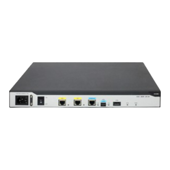
Appendix A Chassis views and technical specifications Chassis views The following figures are for illustration only. MSR 26-30 Figure 52 MSR 26-30 front view (1) Power adapter receptacle (2) Power switch (3) Gigabit Ethernet port (GE0) (4) Gigabit Ethernet port (GE1) (5) Console port/AUX port (CON/AUX) (6) USB console port (CON) (7) USB port... -
Page 52: Msr 26-00-5-Gu-Cnde
MSR 26-00-5-GU-CNDE Figure 54 MSR 26-00-5-GU-CNDE front view (1) USB port (2) Reset button (RESET) Figure 55 MSR 26-00-5-GU-CNDE rear view (1) Power adapter (2) Console port/AUX port (3) Gigabit Ethernet WAN port (GE0) receptacle (CON/AUX) (4) 3G antenna main port (5) Gigabit Ethernet LAN ports (GE1 (6) 3G antenna auxiliary port (DIV) (MAIN) -
Page 53: Msr 26-00-5-Lm-Cnde
Figure 57 MSR 26-00-5-GT-CNDE rear view (1) Power adapter (2) Console port/AUX port (CON/AUX) (3) Gigabit Ethernet WAN port (GE0) receptacle (4) 3G antenna (5) Gigabit Ethernet LAN ports (GE1 to (6) 3G antenna main port (MAIN) auxiliary port (DIV) GE4) (7) Grounding terminal MSR 26-00-5-LM-CNDE... -
Page 54: Msr 26-00-10
MSR 26-00-10 Figure 60 MSR 26-00-10 front view (1) Power adapter receptacle (2) Gigabit Ethernet port (GE1) (3) Gigabit Ethernet ports (GE2 to GE8) (4) Console port/AUX port (5) Reset button (RESET) (6) USB port (CON/AUX) (7) Gigabit Ethernet port (GE0) Figure 61 MSR 26-00-10 rear view (1) SIC slot (slot 3) (2) SIC slot (slot 2) -
Page 55: Technical Specifications
Figure 63 MSR 26-00-17 rear view (1) SIC slot (slot 4) (2) SIC slot (slot 3) (3) SIC slot (slot 2) (4) SIC slot (slot 1) (5) Grounding terminal Technical specifications Item MSR 26-30 26-00-5-GU 26-00-5-GT 26-00-5-LM 26-00-10 26-00-17 Console/AUX port USB console port... -
Page 56: 4G Antenna Specifications
Item MSR 26-30 26-00-5-GU 26-00-5-GT 26-00-5-LM 26-00-10 26-00-17 Dimensions (H × 44.2 × 44.2 × 360 44.2 x 300 x 44.2 x 300 x 44.2 x 300 x 44.2 × 360 W × D) 360 × × 303.5 mm 200 mm 200 mm 200 mm ×... -
Page 57: Antenna Specifications
3G antenna specifications Item Specification Frequency range 806-960 MHz/1710-2170 MHz Voltage Standing Wave Ratio (VSWR) < 2.5 Input impedance 50 ohms Gain 0 dBi Max power consumption 25 W Input interface TNC male Length 254 mm (10 in) Color Gray Weight 45 g (1.59 oz) Operating temperature... -
Page 58: Appendix B Leds
Appendix B LEDs LEDs MSR 26-30 Figure 64 Front panel LEDs (1) Gigabit Ethernet port LED (GE0) (2) Gigabit Ethernet port LED (GE1) (3) Console port LED (4) USB console port LED (5) System LED (SYS) (6) Power module LED (PWR) MSR 26-00-5-GU-CNDE Figure 65 Front panel LEDs (1) System status LED (SYS) -
Page 59: Msr 26-00-5-Gt-Cnde
Figure 66 Rear panel LEDs (1) GE port status LED (yellow) (2) GE port status LED (green) MSR 26-00-5-GT-CNDE Figure 67 Front panel LEDs (1) System status LED (SYS) (2) Network status LED (INTERNET) (3) VPN status LED (VPN) (4) Encryption module LED (6) Received 3G signal strength (5) 3G status LED (WWAN) (CNDE) -
Page 60: Msr 26-00-5-Lm-Cnde
MSR 26-00-5-LM-CNDE Figure 69 Front panel LEDs (1) System status LED (SYS) (2) Network status LED (INTERNET) (3) VPN status LED (VPN) (6) Received 4G signal strength (4) Encryption module LED (CNDE) (5) 4G status LED (WWAN) indication LED (RSSI) Figure 70 Rear panel LEDs (1) GE port status LED (yellow) (2) GE port status LED (green) -
Page 61: Msr 26-00-17
MSR 26-00-17 Figure 72 Front panel LEDs (1) System status LED (SYS) (2) Power module LED (PWR) (3) SFP port LED (SFP16) (4) GE port status LEDs (GE0 to GE15) LED description State Description Comware has started with the configuration file and the router has Flashing green (1 Hz) booted up. - Page 62 State Description The router has been connected to the wireless network and is Steady green operating in 3G mode. Data is being received or transmitted. The router is operating in Flashing green (8 Hz) 3G mode. 3G status The router has been connected to the wireless network and is Steady yellow (WWAN) operating in 2G mode.
-
Page 63: Appendix C Slot Arrangement
Appendix C Slot arrangement The MSR 26-30/MSR 26-00- 1 0/MSR 26-00- 1 7 routers provide slots for SICs. On the MSR 26-30, you can combine slots 1 and 2 into one DSIC slot by removing the slot divider. The slot number of all fixed ports on the router is Slot 0. Table 7 Slot arrangement on the router Router Slot arrangement... -
Page 64: Index
Index A C E G I L M N R S T MSR 26-00- 1 7,47 MSR 26-00- 1 7,54 Attaching the ring terminal,16 26-00-5-GT-CNDE,52 26-00-5-GT-CNDE,45 26-00-5-GU-CNDE,51 Cleanness,2 26-00-5-GU-CNDE,45 Connecting a console cable,28 26-00-5-LM-CNDE,46 Cooling system,2 26-00-5-LM-CNDE,53 26-30,51 Electricity safety,1 26-30,44 EMI,4 prevention,3...
Need help?
Do you have a question about the MSR 2600 Series and is the answer not in the manual?
Questions and answers