Table of Contents
Advertisement
Quick Links
USER GUIDE
MON-10467
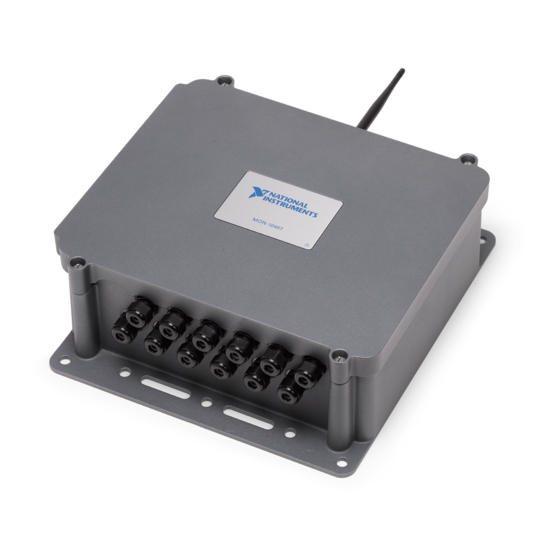
12-Channel Wireless Vibration Measurement Device
MON-10467
This document explains how to install the MON-10467. You can use the MON-10467 to
wirelessly connect up to 12 sensors, such as piezoelectric accelerometers, proximity probes,
tachometers, voltage, and temperature, to your network without conduit for power or network
lines. This device is available in lithium battery, 24 V DC, and 120/220 V AC variants to
support your application's requirements. Rated for outdoor use, the MON-10467 has a rugged
Advertisement
Table of Contents

Related Manuals for National Instruments MON-10467


Summary of Contents for National Instruments MON-10467
- Page 1 12-Channel Wireless Vibration Measurement Device MON-10467 This document explains how to install the MON-10467. You can use the MON-10467 to wirelessly connect up to 12 sensors, such as piezoelectric accelerometers, proximity probes, tachometers, voltage, and temperature, to your network without conduit for power or network lines.
-
Page 2: Table Of Contents
Note In this document, the MON-10467 (AC), MON-10467 (DC), and MON-10467 (BATTERY) are referred to inclusively as the MON-10467. The information in this document applies to all versions of the MON-10467 unless otherwise specified. Note The guidelines in this document are specific to the MON-10467. The other components in the system might not meet the same safety ratings. -
Page 3: Related Documentation
Related Documentation The following documents contain information about the MON-10467. To view them, go to ni.com/manuals. • MON-10467 Safety, Environmental, and Regulatory Information • MON-10467 Specifications For help using your device in InsightCM, refer to the InsightCM Help in software or online at ni.com/r/insightcmhelp. -
Page 4: What You Need To Get Started
(Optional) multi-prong actuation tool (WAGO part number 279-433) • (Optional) 19 mm gland dome nut tightening tool (SEALCON part number S-1900-WR) • (Optional) 24 mm gland dome nut tightening tool (SEALCON part number S-2400-WR) 4 | ni.com | MON-10467 User Guide... -
Page 5: Safety
19 mm deep socket or wrench • 22 mm socket or wrench • (Optional) multi-prong actuation tool (WAGO part number 279-433) • (Optional) 19 mm gland dome nut tightening tool (SEALCON part number S-1900-WR) Safety MON-10467 User Guide | © National Instruments | 5... - Page 6 An external circuit breaker box must be installed according to applicable electrical codes by trained personnel to serve as the power disconnect when installing the MON-10467 (AC). The circuit breaker box must be easy to reach and marked as the power disconnect for the device.
-
Page 7: Electromagnetic Compatibility Notices
The performance of this product can be disrupted if subjected to Electrostatic Discharge (ESD) during operation. To prevent damage, industry- standard ESD prevention measures must be employed during installation, maintenance, and operation. MON-10467 User Guide | © National Instruments | 7... -
Page 8: Parts Diagrams
Parts Diagrams MON-10467 with Door Closed MON-10467 1. Antenna 4. Glands 2. Mounting flanges 5. Door 3. Captive screws 8 | ni.com | MON-10467 User Guide... -
Page 9: Mon-10467 (Ac) Parts Diagram
MON-10467 (AC) Parts Diagram 1. 24 V DC power bus terminals 4. AC power input terminals 2. Reset button 5. Door pocket for desiccant pack 3. Analog input terminals MON-10467 User Guide | © National Instruments | 9... -
Page 10: Mon-10467 (Dc) Parts Diagram
MON-10467 (DC) Parts Diagram 1. 24 V DC power bus terminals 4. Chassis ground screw 2. Reset button 5. Ground shelf 3. Analog input terminals 6. Door pocket for desiccant pack 10 | ni.com | MON-10467 User Guide... -
Page 11: Mon-10467 (Battery) Parts Diagram
1. Battery 5. Chassis ground screw 2. Battery power connector port 6. Ground shelf 3. Reset button 7. Door pocket for desiccant pack 4. Analog input terminals Pinouts Analog Input Pinout MON-10467 User Guide | © National Instruments | 11... -
Page 12: 24 V Dc Power Bus Terminals Pinout
0...11 Chassis ground You can connect ground-referenced or floating signal sources to the MON-10467. Each analog input channel has a 3-pin connector to which you can connect a signal source. The AI+ terminal accepts the positive input signal and provides the IEPE excitation when enabled. The AI- terminal provides the excitation return path and connects to the AI ground reference. -
Page 13: Opening And Closing The Door
Tighten the four captive screws on the door of the device to 1.3 N · m (11.5 lb · in.). Mounting The MON-10467 must be mounted upright to a rigid surface such as a wall, panel, strut channel, or metal post. For installations that may experience vibration, NI recommends using a thread locking compound or lock nuts. -
Page 14: Installing The Antenna And Boot
Place nuts onto the bolts and tighten to secure them. Installing the Antenna and Boot Notice Never apply power or operate the MON-10467 without the antenna installed. Doing so may damage the device. 14 | ni.com | MON-10467 User Guide... -
Page 15: Proximity Probe Drivers And Electronic Accessories
You can use third-party accessories such as proximity probe drivers with the MON-10467 (AC) and MON-10467 (DC). You can install up to two proximity probe drivers per device using the industry-standard 2 in. by 2 in. hole pattern. Refer to the figures below for the hole patterns on the MON-10467 (AC) and MON-10467 (DC). - Page 16 BNC connector. For two-dimensional drawings and three-dimensional models of your device, visit ni.com/dimensions. Figure 3. MON-10467 (AC) Proximity Probe Drivers and Electronic Accessories Hole Pattern 79.2 mm (3.118 in) 50.80 mm 50.80 mm (2.00 in)
- Page 17 119.90 mm (3.50 in) (4.720 in) If you are planning to use proximity probe drivers with the MON-10467 (AC) or MON-10467 (DC), install them before wiring your device. The following figure shows how to connect proximity probe drivers. MON-10467 User Guide | © National Instruments | 17...
-
Page 18: Wiring
Figure 5. Typical Proximity Probe Power and Signal Wiring (MON-10467 (AC) and MON-10467 (DC) only) – AI<a>– –24 VDC Signal OUT AI<a>+ AI<b>– AI<b>+ –24 VDC Signal OUT Typical Proximity Probe Drivers MON-10467 (AC), (Case isolated from Power and Signal) - Page 19 Channels 2, 6, 10 Channels 3, 7, 11 The MON-10467 analog input terminals are referenced to a common AI ground through a 50 Ω resistor. AI ground is not directly accessible. The MON-10467 provides overvoltage protection for each channel. Refer to the MON-10467 Specifications on ni.com/manuals for more information about overvoltage protection.
- Page 20 Connecting Signals You can connect ground-referenced or floating signal sources to the MON-10467. Refer to the following figures for typical IEPE sensor and typical dual sensor wiring. Figure 7. Typical IEPE Sensor Wiring Signal Out / IEPE In AI<0...11>+ (IEPE Source) AI<0...11>–...
- Page 21 Complete the following steps connect signals to the MON-10467. Thread the M16 glands into the device enclosure. Tighten the gland bodies to a torque of 3.16 N · m (28 lb · in.). Install backing nuts onto the M16 glands and tighten to a torque of 2.5 N · m (22.1 lb ·...
- Page 22 MON-10467. IEPE Fault Conditions When IEPE is enabled, the MON-10467 monitors the input voltage to determine if there is a connection issue with the attached signal source. Common connection issues that can occur include open and short circuits.
- Page 23 You may use the gland provided by NI or your own gland. Check the MON-10467 Specifications on ni.com/manuals for the required gland specifications. Note If you are using an alternative gland or fitting, ensure that it is rated for Type 3 or greater and install according to the manufacturer's instructions Insert the PG16 gland through the hole on the enclosure.
- Page 24 Complete the following steps. Confirm that the power source has been turned off. Install the gland on the device enclosure. You may use the gland provided by NI or your own gland. Check the MON-10467 Specifications on ni.com/manuals for the required gland specifications.
- Page 25 Tighten the PG16 dome nut with a 24 mm socket or wrench to a torque of 3.33 N · m (29.5 lb · in.) to provide strain relief and weather resistance for the cables. MON-10467 (BATTERY) Connecting Power and Ground Hardware needed: • M16 gland (supplied by NI) MON-10467 User Guide | © National Instruments | 25...
-
Page 26: Using The Desiccant Kit
You must connect the chassis ground to ensure measurement signal integrity. Complete the following steps. Install the ground cable gland on the device enclosure. You may use the gland provided by NI or your own glands. Check the MON-10467 Specifications on ni.com/manuals for the required gland specifications. - Page 27 Figure 12. Puncturing and Inserting the Desiccant Pack Puncture Here Complete the following steps. If you are using the MON-10467 (AC) or MON-10467 (DC), confirm that the power to the device has been turned off. Loosen the four captive screws on the door of the device.
-
Page 28: Mon-10401 Replacement Battery Pack For The Mon-10467 (Battery)
à une température supérieure à 75 °C et éviter tout contact du contenu avec l'eau. Caution The protection provided by the MON-10467 can be impaired if it is used in a manner not described in the user documentation. Attention La protection apportée par le MON-10467 risque d'être endommagée s'il... -
Page 29: Battery Pack Recycling
This service helps reduce the impact on landfills and other disposal sites and provides an environmentally safe end-of-life solution. Hardware products can be sent to NI for recycling by emailing recycling@ni.com. MON-10467 User Guide | © National Instruments | 29... -
Page 30: Using The Reset Button
Using the Reset Button The MON-10467 has a physical reset button that you can use to delete the stored password and gateway bonding information from the device. On the MON-10467 (BATTERY), the reset button can also be used to restart the device. You can restart the MON-10467 (AC) and MON-10467 (DC) by cycling power to the device. - Page 31 11. Tighten the four captive screws on the door of the device to 1.3 N · m (11.5 lb · in.). Using the Reset Button on the MON-10467 (DC) Caution Remove power to the MON-10467 (DC) before opening it for service. Attention Mettez le MON-10467 (DC) hors tension avant de l'ouvrir pour l'entretien.
-
Page 32: Where To Go Next
Tighten the four captive screws on the door of the device to 1.3 N · m (11.5 lb · in.). Where to Go Next After you have finished mounting and connecting your MON-10467 wireless vibration measurement device, finish setting up your system by doing the following. - Page 33 NI trademarks. Other product and company names mentioned herein are trademarks or trade names of their respective companies. For patents covering NI products/technology, refer to the appropriate location: Help»Patents in your software, the file on your media, or the National Instruments Patent Notice at . You can find patents.txt ni.com/patents...
Need help?
Do you have a question about the MON-10467 and is the answer not in the manual?
Questions and answers