Viessmann VITOTROL 200-E Installation And Service Instructions Manual
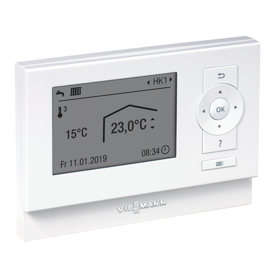
Remote control for up to 4 heating circuits
Hide thumbs
Also See for VITOTROL 200-E:
- Operating instructions manual (36 pages) ,
- Installation and service instructions manual (21 pages) ,
- Installation and service instructions manual (12 pages)

Related Manuals for Viessmann VITOTROL 200-E


Summary of Contents for Viessmann VITOTROL 200-E
- Page 1 VIESMANN Installation and service instructions for contractors Vitotrol 200-E Remote control for up to 4 heating circuits VITOTROL 200-E Please keep safe. 5839309 GB 7/2018...
- Page 2 Danger system. Hot surfaces and fluids can lead to burns or Replace faulty components only with genuine scalding. Viessmann spare parts. Before maintenance and service work, switch ■ OFF the appliance and let it cool down. ■ Never touch hot surfaces on the boiler, burner,...
- Page 3 For replacements, use only original spare parts supplied or approved by Viessmann. Safety instructions for operating the system If you smell gas Condensate Danger...
-
Page 4: Table Of Contents
■ Preparing for installation System requirements ................Installation sequence Place of installation ................Fitting and connecting the Vitotrol 200-E ..........Connecting several remote controls ............Fitting and removing the programming unit ........... 10 Commissioning Configuring the remote control .............. 11 Reconfiguration .................. -
Page 5: Disposal Of Packaging
Viessmann heat and power generators designed for this system. Also take account of the rele- Incorrect usage or operation of the appliance (e.g. the vant installation, service and operating instructions. -
Page 6: Product Information
Product information Vitotrol 200-E Wired remote control for connection to Viessmann Holiday program and "Holiday at home" function ■ heat generators Time programs for heating circuits and DHW cylinder ■... -
Page 7: System Requirements
Preparing for installation System requirements Supported control units For an up to date overview of the supported control units: See www.vitotrol.info... -
Page 8: Place Of Installation
– Not near heat sources (direct sunlight, fireplace, – TV set, etc.) Fitting and connecting the Vitotrol 200-E Please note Connection Electronic assemblies can be damaged by elec- 2-core cable with a cross-section of at least 0.75 mm²;... -
Page 9: Connecting Several Remote Controls
Connection to plug & play plug: Heat generator installation and service instruc- tions Connecting several remote controls Two Vitotrol 200-E can be connected to the same con- Total length of all PlusBus cables max. 50 m. trol unit. Version 1... -
Page 10: Fitting And Removing The Programming Unit
Installation sequence Fitting and removing the programming unit Please note The remote control is supplied with power by the control unit. Never insert batteries into the battery compart- ment. Fitting Removing Fig. 5 Fig. 6... -
Page 11: Configuring The Remote Control
Up to 4 heating circuits can be controlled with a The remote control must be configured during commis- Vitotrol 200-E. sioning: Up to 2 Vitotrol 200-E can be connected to one control ■ If no Vitotrol 200-E has previously been connected to unit. -
Page 12: Configuring An Additional Remote Control
Commissioning Configuring the remote control (cont.) Configuring an additional remote control 1. Call up the subscriber number of the existing 3. Follow the steps detailed in chapter "Reconfigura- remote control at the control unit of the heat gener- tion". Set the subscriber number specified in the ator: table. -
Page 13: Service Indication
Troubleshooting Service indication If the heating system is due for a service, the sym- Call up the submenu with the OK key to acknowledge bol flashes on the display and "Service" is shown. all current service messages. Further information on the pending service: Control unit installation and service instructions Fault display In the event of a fault, the... - Page 14 Troubleshooting Fault display (cont.)
-
Page 15: Ordering Parts
Parts lists Ordering parts The following details are required when ordering parts: ■ Serial no. (see type plate ■ Position number of the part (from this parts list) -
Page 16: Vitotrol 200-E
Parts lists Vitotrol 200-E 0001 0003 0002 0004 0005 0006 Fig. 7... - Page 17 Parts lists Vitotrol 200-E (cont.) Pos. Part 0001 Programming unit 0002 Wall mounting base 0003 Cover, wiring chamber 0004 Fixing materials and plugs 0005 Installation instructions 0006 Operating instructions...
-
Page 18: Specification
Appendix Specification Power supply Via PlusBus Voltage Current Protection class Permissible ambient temperature Operation °C 0 to +40 ■ Storage and transport °C 20 to +65 °C − ■... -
Page 19: Declaration Of Conformity
Certificates Declaration of conformity We, Viessmann Werke GmbH & Co. KG, D-35107 Allendorf, declare as sole responsible body that the named product complies with the European directives and supplementary national requirements in terms of its design and operational characteristics. Conformity has been verified with the CE designation. - Page 20 Temperatures............. 18 – Operation with room temperature hook-up....8 – Weather-compensated operation......8 Installation conditions...........8 Installation room............6 Intended use..............5 Viessmann Werke GmbH & Co. KG Viessmann Limited D-35107 Allendorf Hortonwood 30, Telford Telephone: +49 6452 70-0 Shropshire, TF1 7YP, GB...
Need help?
Do you have a question about the VITOTROL 200-E and is the answer not in the manual?
Questions and answers