
Related Manuals for WAGO 750-341


Summary of Contents for WAGO 750-341
- Page 1 Modular I/O-System ETHERNET TCP/IP 750-341 Manual Technical description, installation and configuration Version 1.1.1...
- Page 2 • General Copyright © 2007 by WAGO Kontakttechnik GmbH & Co. KG All rights reserved. WAGO Kontakttechnik GmbH & Co. KG Hansastraße 27 D-32423 Minden Phone: +49 (0) 571/8 87 – 0 Fax: +49 (0) 571/8 87 – 1 69 E-Mail: info@wago.com...
-
Page 3: Table Of Contents
Font Conventions ..................6 Number Notation ..................6 Scope ......................2 Important Comments for Starting up............7 Abbreviation..................... 7 2 The WAGO-I/O-SYSTEM 750 ..............8 System Description................... 8 Technical Data..................9 Manufacturing Number ................15 Component Update................. 16 Storage, Assembly and Transport ............16 Mechanical Setup ................... - Page 4 Shielding (Screening) ................39 2.9.1 General....................39 2.9.2 Bus Conductors.................. 39 2.9.3 Signal Conductors................39 2.9.4 WAGO Shield (Screen) Connecting System........40 2.10 Assembly Guidelines/Standards............. 40 3 Fieldbus Coupler ..................41 Fieldbus Coupler 750-341 ..............41 3.1.1 Description..................41 3.1.2 Hardware.................... 42 3.1.2.1...
- Page 5 Description of the MODBUS Functions ......... 120 4.2.3.1 Function Code FC1 (Read Coils)..........121 4.2.3.2 Function Code FC2 (Read Input Discretes)........ 122 4.2.3.3 Function Code FC3 (Read multiple registers) ......123 4.2.3.4 Function code FC4 (Read input registers) ........124 WAGO-I/O-SYSTEM 750 ETHERNET TCP/IP...
- Page 6 Object model..................148 4.3.3.1 General ..................148 4.3.3.2 Classes..................149 4.3.3.2.1 CIP Common Classes..............149 4.3.3.2.2 WAGO specific Classes.............. 149 4.3.3.2.3 Explanations of the Object Description ........150 4.3.3.2.4 Identity (01 ) ................150 4.3.3.2.5 Message Router (02 ) .............. 151 4.3.3.2.6...
- Page 7 Explosion protection groups............218 7.4.3 Temperature classes................. 219 Identification ..................220 7.5.1 For Europe ..................220 7.5.2 For America ..................221 Installation regulations ................. 222 8 Glossary....................224 9 Literature List ..................236 10 Index ......................237 WAGO-I/O-SYSTEM 750 ETHERNET TCP/IP...
-
Page 8: Important Notes
WAGO Kontakttechnik GmbH & Co. KG, Minden. Non-observance will entail the right of claims for damages. WAGO Kontakttechnik GmbH & Co. KG reserves the right of changes serving technical progress. All rights developing from the issue of a patent or the legal protection of utility patents are reserved to WAGO Kontakttechnik GmbH &... -
Page 9: Conforming Use Of Series 750
Important Notes • 3 Standards and Regulations for Operating the 750 Series improper action and damage to WAGO products and third party products due to non-observance of the information contained in this manual. 1.1.3 Conforming Use of Series 750 The couplers and controllers of the modular I/O System 750 receive digital and analog signals from the I/O modules and sensors and transmit them to the actuators or higher level control systems. -
Page 10: Symbols
Observe the precautionary measure for handling components at risk of electrostatic discharge. Note Make important notes that are to be complied with so that a trouble-free and efficient device operation can be guaranteed. Additional Information References to additional literature, manuals, data sheets and INTERNET pages. WAGO-I/O-SYSTEM 750 ETHERNET TCP/IP... -
Page 11: Safety Information
Danger The WAGO-I/O-SYSTEM 750 and its components are an open system. It must only be assembled in housings, cabinets or in electrical operation rooms. Access is only permitted via a key or tool to authorized qualified personnel. -
Page 12: Font Conventions
C notation Binary '100' Within ', '0110.0100' Nibble separated with dots 1.7 Scope This manual describes the field bus independent WAGO-I/O-SYSTEM 750 with the fieldbus coupler for ETHERNET 10/100 MBit/s. Item.-No. Description 750-341 Fieldbus Coupler EtherNet 10/100 MBit/s WAGO-I/O-SYSTEM 750... -
Page 13: Important Comments For Starting Up
Important Comments for Starting up 1.8 Important Comments for Starting up Attention For the start-up of the coupler 750-341 important notes are to be considered, because it strongly differentiates in some points of starting up the WAGO ETHERNET coupler 750-342. -
Page 14: The Wago-I/O-System 750
The WAGO-I/O-SYSTEM 750 has a clear port level with LEDs for status indication, insertable mini WSB markers and pullout group marker carriers. The 3-wire technology supplemented by a ground wire connection allows for direct sensor/actuator wiring. -
Page 15: Technical Data
Maximum pollutant concentration at S ≤ 10 ppm relative humidity < 75% Special conditions Ensure that additional measures for components are taken, which are used in an environment involving: – dust, caustic vapors or gasses – ionization radiation. WAGO-I/O-SYSTEM 750 ETHERNET TCP/IP... - Page 16 10 • The WAGO-I/O-SYSTEM 750 Technical Data Safe electrical isolation Air and creepage distance acc. to IEC 60664-1 Degree of pollution acc. To IEC 61131-2 Degree of protection Degree of protection IP 20 Electromagnetic compatibility Immunity to interference for industrial areas acc. to EN 61000-6-2 (2001)
- Page 17 IEC 60068-2-32 free fall (module in original packing) *) QP: Quasi Peak Note: If the technical data of components differ from the values described here, the technical data shown in the manuals of the respective components shall be valid. WAGO-I/O-SYSTEM 750 ETHERNET TCP/IP...
- Page 18 12 • The WAGO-I/O-SYSTEM 750 Technical Data For Products of the WAGO-I/O-SYSTEM 750 with ship specific approvals, supplementary guidelines are valid: Electromagnetic compatibility Immunity to interference acc. to Germanischer Lloyd (2003) Test specification Test values Strength Evaluation class criteria IEC 61000-4-2 ESD...
- Page 19 In Germany, the Federal Office for Post and Telecommunications and its branch offices issues the permit. It is possible to use other field bus couplers/controllers under certain boundary conditions. Please contact WAGO Kontakttechnik GmbH & Co. KG. Maximum power dissipation of the components Bus modules 0.8 W / bus terminal (total power dissipation,...
- Page 20 14 • The WAGO-I/O-SYSTEM 750 Technical Data Dimensions 01 02 24V 0V Side view Dimensions in mm Fig. 2-2: Dimensions g01xx05e Note: The illustration shows a standard coupler. For detailed dimensions, please refer to the technical data of the respective coupler/controller.
-
Page 21: Manufacturing Number
Fig. 2-3: Example: Manufacturing Number of a PROFIBUS fieldbus coupler 750-333 g01xx15e The manufacturing number consists of the production week and year, the software version (if available), the hardware version of the component, the firmware loader (if available) and further internal information for WAGO Kontakttechnik GmbH. WAGO-I/O-SYSTEM 750 ETHERNET TCP/IP... -
Page 22: Component Update
16 • The WAGO-I/O-SYSTEM 750 Component Update 2.4 Component Update For the case of an Update of one component, the lateral marking on each component contains a prepared matrix. This matrix makes columns available for altogether three updates to the entry of the current update data, like production order number (NO;... -
Page 23: Mechanical Setup
Attention In the case of vertical assembly, an end stop has to be mounted as an additional safeguard against slipping. WAGO item 249-116 End stop for DIN 35 rail, 6 mm wide WAGO item 249-117 End stop for DIN 35 rail, 10 mm wide 2.6.2 Total Expansion... -
Page 24: Assembly Onto Carrier Rail
European standard EN 50022 (DIN 35). Warning WAGO supplies standardized carrier rails that are optimal for use with the I/O system. If other carrier rails are used, then a technical inspection and approval of the rail by WAGO Kontakttechnik GmbH should take place. -
Page 25: Wago Din Rail
Mechanical Setup • 19 Spacing 2.6.3.2 WAGO DIN Rail WAGO carrier rails meet the electrical and mechanical requirements. Item Number Description 210-113 /-112 35 x 7.5; 1 mm; steel yellow chromated; slotted/unslotted 210-114 /-197 35 x 15; 1.5 mm; steel yellow chromated; slotted/unslotted 210-118 35 x 15;... -
Page 26: Plugging And Removal Of The Components
20 • The WAGO-I/O-SYSTEM 750 Mechanical Setup 2.6.5 Plugging and Removal of the Components Warning Before work is done on the components, the voltage supply must be turned off. In order to safeguard the coupler/controller from jamming, it should be fixed onto the carrier rail with the locking disc To do so, push on the upper groove of the locking disc using a screwdriver. -
Page 27: Assembly Sequence
4-channel digital input module, has a decreased air and creepage distance to the neighboring contact in the example DI4. Always terminate the fieldbus node with an end module (750-600). WAGO-I/O-SYSTEM 750 ETHERNET TCP/IP... -
Page 28: Internal Bus/Data Contacts
22 • The WAGO-I/O-SYSTEM 750 Mechanical Setup 2.6.7 Internal Bus/Data Contacts Communication between the coupler/controller and the bus modules as well as the system supply of the bus modules is carried out via the internal bus. It is comprised of 6 data contacts, which are available as self-cleaning gold spring contacts. -
Page 29: Power Contacts
Fig. 2-8: Example for the arrangement of power contacts g0xxx05e Recommendation With the WAGO ProServe® Software smartDESIGNER, the assembly of a fieldbus node can be configured. The configuration can be tested via the integrated accuracy check. WAGO-I/O-SYSTEM 750... -
Page 30: Wire Connection
More than one conductor per connection is not permissible. If several conductors have to be made at one connection point, then they should be made away from the connection point using WAGO Terminal Blocks. The terminal blocks may be jumpered together and a single wire brought back to the I/O module connection point. -
Page 31: Power Supply
When using a joint power supply unit for the 24 V system supply and the 24 V field supply, the electrical isolation between the internal bus and the field level is eliminated for the potential group. WAGO-I/O-SYSTEM 750 ETHERNET TCP/IP... -
Page 32: System Supply
2.7.2 System Supply 2.7.2.1 Connection The WAGO-I/O-SYSTEM 750 requires a 24 V direct current system supply (-15% or +20 %). The power supply is provided via the coupler/controller and, if necessary, in addition via the internal system supply modules (750-613). -
Page 33: Alignment
20* 90 mA = 1800 mA 10* 2 mA = 20 mA 1820 mA The coupler can provide 1650 mA for the bus modules. Consequently, an internal system supply module (750-613), e.g. in the middle of the node, should be added. WAGO-I/O-SYSTEM 750 ETHERNET TCP/IP... - Page 34 The WAGO-I/O-SYSTEM 750 Power Supply Recommendation With the WAGO ProServe® Software smartDESIGNER, the assembly of a fieldbus node can be configured. The configuration can be tested via the integrated accuracy check. The maximum input current of the 24 V system supply is 500 mA. The exact...
-
Page 35: Field Supply
By inserting an additional power supply module, the field supply via the power contacts is disrupted. From there a new power supply occurs which may also contain a new voltage potential. WAGO-I/O-SYSTEM 750 ETHERNET TCP/IP... -
Page 36: Fusing
30 • The WAGO-I/O-SYSTEM 750 Power Supply Attention Some bus modules have no or very few power contacts (depending on the I/O function). Due to this, the passing through of the relevant potential is disrupted. If a field supply is required for subsequent bus modules, then a power supply module must be used. - Page 37 Lifting the cover to the side opens the fuse carrier. Fig. 2-16: Opening the fuse carrier p0xxx03x Fig. 2-17: Change fuse p0xxx04x After changing the fuse, the fuse carrier is pushed back into its original position. WAGO-I/O-SYSTEM 750 ETHERNET TCP/IP...
- Page 38 32 • The WAGO-I/O-SYSTEM 750 Power Supply Alternatively, fusing can be done externally. The fuse modules of the WAGO series 281 and 282 are suitable for this purpose. Fig. 2-18: Fuse modules for automotive fuses, Series 282 pf66800x Fig. 2-19: Fuse modules with pivotable fuse carrier, Series 281 pe61100x Fig.
-
Page 39: Supplementary Power Supply Regulations
Supplementary power supply regulations 2.7.4 Supplementary power supply regulations The WAGO-I/O-SYSTEM 750 can also be used in shipbuilding or offshore and onshore areas of work (e.g. working platforms, loading plants). This is demonstrated by complying with the standards of influential classification companies such as Germanischer Lloyd and Lloyds Register. -
Page 40: Supply Example
34 • The WAGO-I/O-SYSTEM 750 Power Supply 2.7.5 Supply example Note The system supply and the field supply should be separated in order to ensure bus operation in the event of a short-circuit on the actuator side. 750-400 750-410 750-401... -
Page 41: Power Supply Unit
• 35 Power Supply Unit 2.7.6 Power Supply Unit The WAGO-I/O-SYSTEM 750 requires a 24 V direct current system supply with a maximum deviation of -15% or +20 %. Recommendation A stable network supply cannot be taken for granted always and everywhere. -
Page 42: Grounding
The optimal insulated setup is a metallic assembly plate with grounding connection with an electrical conductive link with the carrier rail. The separate grounding of the carrier rail can be easily set up with the aid of the WAGO ground wire terminals. Article No. Description... -
Page 43: Grounding Function
Attention Care must be taken to ensure the direct electrical connection between the carrier rail contact and the carrier rail. The carrier rail must be grounded. For information on carrier rail properties, please see chapter 2.6.3.2. WAGO-I/O-SYSTEM 750 ETHERNET TCP/IP... -
Page 44: Grounding Protection
38 • The WAGO-I/O-SYSTEM 750 Grounding 2.8.3 Grounding Protection For the field side, the ground wire is connected to the lowest connection terminals of the power supply module. The ground connection is then connected to the next module via the Power Jumper Contact (PJC). If the bus... -
Page 45: Shielding (Screening)
Note For better shield performance, the shield should have previously been placed over a large area. The WAGO shield connection system is suggested for such an application. This suggestion is especially applicable when the equipment can have even current or high impulse formed currents running through it (for example through atmospheric end loading). -
Page 46: Wago Shield (Screen) Connecting System
Assembly Guidelines/Standards 2.9.4 WAGO Shield (Screen) Connecting System The WAGO Shield Connecting system includes a shield clamping saddle, a collection of rails and a variety of mounting feet. Together these allow many dfferent possibilities. See catalog W4 volume 3 chapter 10. -
Page 47: Fieldbus Coupler
3 Fieldbus Coupler 3.1 Fieldbus Coupler 750-341 3.1.1 Description The fieldbus coupler 750-341 displays the peripheral data of all I/O modules in the WAGO-I/O-SYSTEM 750 on ETHERNET. When power is applied to the fieldbus coupler, it automatically detects all I/O modules connected to the coupler and creates a local process image. -
Page 48: Hardware
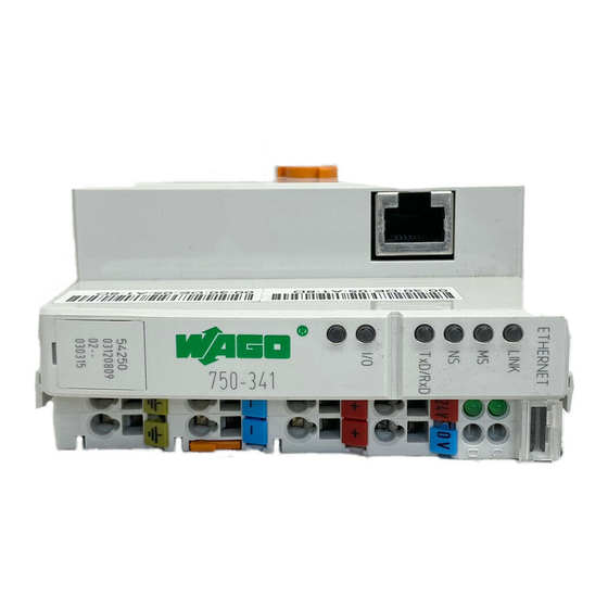
42 • Fieldbus Coupler Fieldbus Coupler 750-341 3.1.2 Hardware 3.1.2.1 View status ETHERNET 01 02 voltage supply LINK -power jumper contacts fieldbus -system connection data contacts 24V 0V RJ 45 TxD/RxD supply supply via power jumper contacts flap open power jumper contacts... -
Page 49: Device Supply
Fieldbus Coupler 750-341 • 43 Hardware 3.1.2.2 Device supply The supply is made via terminal bocks with CAGE CLAMP® connection. The device supply is intended both for the system and the field units 24 V 24 V /0 V 10 nF... -
Page 50: Display Elements
Status of the operating voltage – power jumper contacts (LED position is manufacturing dependent) 3.1.2.5 Configuration interface The configuration interface used for the communication with WAGO-I/O- CHECK or for firmware download is located behind the cover flap. open flap... -
Page 51: Hardware Address (Mac-Id)
3.1.2.6 Hardware address (MAC-ID) Each WAGO ETHERNET fieldbus coupler is provided from the factory with a unique and internationally unambiguous physical ETHERNET address, also referred to as MAC-ID (Media Access Control Identity). This address is to be found on the rear of the coupler and on an adhesive tear-off label on the side of the coupler. -
Page 52: Process Image
The maximal length of a node is limited to 64 I/O modules. Note Use of the WAGO 750-628 Bus Extension Coupler Module and the 750-627 Extension End Module enables support of up to 250 I/O modules on the 750-341 coupler. - Page 53 Fieldbus Coupler 750-341 • 47 Process image In contrast to the above, access from the fieldbus side is fieldbus specific. For the ETHERNET TCP/IP fieldbus coupler, either a MODBUS/TCP master or an Ethernet/IP master is used. MODBUS/TCP accesses the data via implemented MODBUS functions.
-
Page 54: Example Of A Process Input Image
48 • Fieldbus Coupler Fieldbus Coupler 750-341 3.1.4.1 Example of a Process Input Image The following figure is an example of a process input image. The configuration includes 16 digital and 8 analog inputs. Therefore, the process image has a total data length of 9 words (8 words for the analog data and 1 word for the digital inputs). -
Page 55: Example Of A Process Output Image
Fieldbus Coupler 750-341 • 49 Process image 3.1.4.2 Example of a Process Output Image The following figure is an example of a process output image. The configuration includes 2 digital and 4 analog outputs. Therefore, the process image has a total data length of 5 (4 words for the analog data and 1 word for the digital outputs). -
Page 56: Process Data Architecture
Intel format. More Information You can find the fieldbus specific process data architecture for all I/O Modules of the WAGO-I/O-SYSTEM 750 and 753 in the chapter „Process Data Architecture“. 3.1.5 Data Exchange The ETHERNET TCP/IP fieldbus coupler can be configured for either MODBUS/TCP or the Ethernet IP protocol. -
Page 57: Memory Areas
Fieldbus Coupler 750-341 • 51 Data Exchange used for the data access an object model. The addressing of the data is in each case different thereby very. 3.1.5.1 Memory areas Programmable Fieldbus Controller memory area for input data word 0... -
Page 58: Addressing The I/O Modules
52 • Fieldbus Coupler Fieldbus Coupler 750-341 3.1.5.2 Addressing the I/O modules The arrangement of the I/O modules in a node is optional. When addressing, first of all the more complex modules (modules occupying 1 or more bytes) are taken into account in accordance with their physical order behind the fieldbus coupler. - Page 59 Fieldbus Coupler 750-341 • 53 Data Exchange 15. 14. 13. 12. 11. 10. 9. Digital Inputs/Outputs Process data word High-Byte Low-Byte Byte Table 3.1.2: Allocation of digital inputs/outputs to process data word acc. Intel format The outputs can be read back by adding 0x0200 to the MODBUS address.
-
Page 60: Data Exchange Between Ethernet/Ip Master And I/O Modules
54 • Fieldbus Coupler Fieldbus Coupler 750-341 3.1.5.4 Data Exchange between EtherNet/IP Master and I/O Modules Data exchange between the EtherNet/IP master and the I/O modules is object oriented. Each node in the network is represented as a collection of objects. -
Page 61: Starting Up A Fieldbus Node
HTML pages. Attention When starting up the 750-341 coupler, there are a number of important factors to consider, since the start-up of this coupler differs significantly in certain respects from the 750-342 ETHERNET coupler. -
Page 62: Connecting Pc And Fieldbus Node
56 • Fieldbus Coupler Fieldbus Coupler 750-341 3.1.6.2 Connecting PC and fieldbus node Connect the assembled ETHERNET TCP/IP fieldbus node via a hub or directly to the PC using a 10Base-T cable. The transmission rate of the coupler is dependant on the baud rate of the PC network interface card.. -
Page 63: Allocating The Ip Address To The Fieldbus Node
3.1.6.4 Allocating the IP address to the fieldbus node The following describes how to allocate the IP address for the fieldbus node using the WAGO BootP server by way of an example. You can download a free copy from WAGO over the Internet under: http://www.wago.com/wagoweb/usa/eng/support/downloads/index.htm. - Page 64 58 • Fieldbus Coupler Fieldbus Coupler 750-341 Fig. 3.1-8: BootP table p012908e The examples mentioned above contain the following information: Declaration Meaning node1, Any name can be given for the node here. node2 ht=1 Specify the hardware type of the network here.
- Page 65 File menu, menu item Save, and close the editor. BootP Server 7. Now open the dialog window for the WAGO BootP server by going to the Start menu on your screen surface, menu item Program / WAGO Software / WAGO BootP Server and click on WAGO BootP Server.
-
Page 66: Testing The Function Of The Fieldbus Node
60 • Fieldbus Coupler Fieldbus Coupler 750-341 3.1.6.5 Testing the function of the fieldbus node 1. To test the communication with the coupler and the correct assignment of the IP address call up the DOS prompt under Start menu / Program / MS- DOS Prompt. - Page 67 Fieldbus Coupler 750-341 • 61 Starting up a Fieldbus Node 3. To logon as the administrator, enter the user name admin and the password wago. One of the coupler’s built-in web pages is displayed. The opening page displays information about your fieldbus coupler. You can get further information by clicking the hyperlinks on the left navigation bar.
- Page 68 62 • Fieldbus Coupler Fieldbus Coupler 750-341 Click the "Port" hyperlink on the left navigation bar. 5. A list of all protocols supported by the coupler is displayed. The BootP protocol is activated by default. To disable the protocol, click on the check box after BootP to remove the check mark.
-
Page 69: Information On The Web-Based Management System
Fieldbus Coupler 750-341 • 63 Information on the Web-Based Management System 3.1.7 Information on the Web-Based Management System In addition to the web pages already described in section 3, the following HTML pages are stored in your coupler and provide information and configuration options. - Page 70 64 • Fieldbus Coupler Fieldbus Coupler 750-341 SNMP Configuration Under the Snmp link, you can view and change settings for the Simple Network Management Protocol, which is responsible for the transport of control data. More information For detailed information to the settings and the configuration of SNMP please refer the following chapter "Configuration of SNMP".
- Page 71 Fieldbus Coupler 750-341 • 65 Information on the Web-Based Management System Under the Watchdog link, you can view and change settings for the MODBUS Watchdog. Clock Configuration Under the Clock link, you can view and change settings for the coupler’s internal real time clock.
- Page 72 66 • Fieldbus Coupler Fieldbus Coupler 750-341 Web Security Under the Web security link, you can setup read/write access rights by using passwords for different user groups in order to protect against configuration changes. The following groups are provided for this:...
-
Page 73: Configuration Of Snmp
Fieldbus Coupler 750-341 • 67 Configuration of SNMP 3.1.8 Configuration of SNMP The Simple Network Management Protocol (SNMP) is responsible for the transport of control data, which enables the exchange of management information, status and statistical data between individual network components and a management system. -
Page 74: System Group
68 • Fieldbus Coupler Fieldbus Coupler 750-341 3.1.8.1.1 System Group The System Group contains general information to the coupler/controller. Identifier Entry Description cess 1.3.6.1.2.1.1.1 sysDescr This entry contains the device identification. The entry is fix coded e. g. on "WAGO 750-841". - Page 75 Fieldbus Coupler 750-341 • 69 Configuration of SNMP testing(3) : Interface is in the test mode 1.3.6.1.2.1.2.2.1.8 ifOperStatus This entry indicates the current condition of the interface. 1.3.6.1.2.1.2.2.1.9 ifLastChange This entry indicates the value of sysUpTime at the time in which the condition changed for the last time.
-
Page 76: Address Translation Group
70 • Fieldbus Coupler Fieldbus Coupler 750-341 3.1.8.1.3 Address Translation Group The Address Translation Group contains information about ARP (Address Resolution Protocol) of the coupler/controller. Entry Description Identifier cess 1.3.6.1.2.1.3.1 atTable Contains the allocation between network address and hardware address. - Page 77 Fieldbus Coupler 750-341 • 71 Configuration of SNMP 1.3.6.1.2.1.4.17 ipFragOKs Number of IP Frames that were fragmented and passed on 1.3.6.1.2.1.4.18 ipFragFails Number of IP Frames that had to be discarded because they need to be fragmented at this entity, but could not 1.3.6.1.2.1.4.19...
-
Page 78: Iproute Table
72 • Fieldbus Coupler Fieldbus Coupler 750-341 3.1.8.1.5 IpRoute Table The IP Route Table contains information about the Routing table in the coupler/controller. Entry Description Identifier cess 1.3.6.1.2.1.4.21 ipRouteTable IP Routing table 1.3.6.1.2.1.4.21.1 ipRouteEntry A Routing entry for a special destination 1.3.6.1.2.1.4.21.1.1... -
Page 79: Icmp Group
Fieldbus Coupler 750-341 • 73 Configuration of SNMP 3.1.8.1.7 ICMP Group Identifier Entry Description cess 1.3.6.1.2.1.5.1 icmpInMsgs Number of received ICMP messages 1.3.6.1.2.1.5.2 icmpInErrors Number of received ICMP messages that contain the ICMP specific errors 1.3.6.1.2.1.5.3 icmpInDestUnreachs Number of received ICMP destination unreachable messages 1.3.6.1.2.1.5.4... -
Page 80: Tcp Group
74 • Fieldbus Coupler Fieldbus Coupler 750-341 3.1.8.1.8 TCP Group Identifier Entry Description cess 1.3.6.1.2.1.6.1 tcpRtoAlgorithm Retransmission time ( 1 = another, 2 = constant, 3 = MIL standard 1778, 4 = Jacobson) 1.3.6.1.2.1.6.2 tcpRtoMin Minimum value for the retransmission timer 1.3.6.1.2.1.6.3... -
Page 81: Snmp Group
Fieldbus Coupler 750-341 • 75 Configuration of SNMP applications (port unreachable) 1.3.6.1.2.1.7.3 udpInErrors Number of received UDP frames that could not be passed on the appropriate applications for other reasons. 1.3.6.1.2.1.7.4 udpOutDatagrams Number of sent UDP frames 1.3.6.1.2.1.7.5 udpTable For each application, which received UDP frames, a table entry is produced 1.3.6.1.2.1.7.5.1... -
Page 82: Egp-Group
76 • Fieldbus Coupler Fieldbus Coupler 750-341 contained the result too Big 1.3.6.1.2.1.11.21 snmpOutNoSuch Number of sent SNMP frames that Names contained the result noSuchName 1.3.6.1.2.1.11.22 snmpOutBadValues Number of sent SNMP frames that contained the result bad value 1.3.6.1.2.1.11.24 SnmpOutGenErrs... -
Page 83: Led Display
24V 0V TxD/RxD TxD/RxD TxD/RxD Fig. 3.1-11: Display elements 750-341 g034102x The LEDs can be divided into three groups. The first group of LEDs display the status of the Ethernet fieldbus. It contains both solid and two-color LEDs. They are labelled as: ‘LINK‘ (green), ‘MS‘... -
Page 84: Fieldbus Status
78 • Fieldbus Coupler Fieldbus Coupler 750-341 3.1.9.1 Fieldbus status The health of the ETHERNET Fieldbus is signalled through the top LED group (‘LINK‘, ‘MS‘, ‘NS‘ and ‘TxD/RxD‘). The two-colored LEDs ‘MS’ (module status) and ‘NS’ (network status) are solely used by the Ethernet/IP protocol. -
Page 85: Node Status - Blink Code From The 'I/O' Led
Fieldbus Coupler 750-341 • 79 LED Display 3.1.9.2 Node status – Blink code from the 'I/O' LED The ‘I/O‘-LED displays the communication status of the internal bus. Additionally, this LED is used to display fault codes (blink codes) in the event of a system error. - Page 86 80 • Fieldbus Coupler Fieldbus Coupler 750-341 Switching on the power supply Coupler/Controller starts up “I/O”-LED is blinking Test o.k.? “I/O” LED 1st flash sequence (Introduction of the error indication) 1st break “I/O” LED 2nd flash sequence Error code (Number of flash cycles) 2nd break “I/O”...
- Page 87 Fieldbus Coupler 750-341 • 81 LED Display Fault message of the ‘I/O‘-LED 1 st flash sequence: Start of the Fault message 2 nd flash sequence: Fault code 3 rd flash sequence: Fault argument Fault code 1: "Hardware and Configuration fault"...
- Page 88 82 • Fieldbus Coupler Fieldbus Coupler 750-341 Timeout when writing data in the Turn off the power supply of the EEPROM node, exchange fieldbus coupler and turn the power supply on again. Bus Coupler initialization fault Turn off the power supply of the...
- Page 89 Fieldbus Coupler 750-341 • 83 LED Display Internal bus communication If the fieldbus node comprises malfunction; faulty device can’t internal system supply modules be detected (750-613), make sure first that the power supply of these modules is functioning. This is indicated by the status LEDs.
- Page 90 84 • Fieldbus Coupler Fieldbus Coupler 750-341 Fault code 4: "Internal bus physical fault" Fault argument Fault description Trouble shooting Error in internal bus data Turn off the power supply of the communication or interruption of node. Place an I/O module with...
- Page 91 Fieldbus Coupler 750-341 • 85 LED Display Fault code 5: "Internal bus initialization fault" Fault argument Fault description Trouble shooting Error in register communication Turn off the power supply of the during internal bus initialization node and replace n process data module and turn the power supply on again.
-
Page 92: Supply Voltage Status
86 • Fieldbus Coupler Fieldbus Coupler 750-341 3.1.9.3 Supply voltage status The two green LED’s in the coupler supply section, display the status of the supply voltage. The left LED (A) indicates the status of the 24 V supply for the coupler. -
Page 93: Fault Behavior
Fieldbus Coupler 750-341 • 87 Fault behavior 3.1.10 Fault behavior 3.1.10.1 Fieldbus failure A field bus failure is given i. e. when the master cuts-out or the bus cable is interrupted. A fault in the master can also lead to a fieldbus failure. -
Page 94: Technical Data
ETHERNET specification Twisted Pair S-UTP 100 Ω cat. 5 Transmission medium Buscoupler connection RJ45 Max. length of fieldbus segment 100 m between hub station and 750-341; max. length of network limited by ETHERNET specification Baud rate 10/100 Mbit/s Protocols... - Page 95 Fieldbus Coupler 750-341 • 89 Technical Data Approvals (cf. Chapter 2.2) (UL508) ABS (American Bureau of Shipping) BV (Bureau Veritas) GL (Germanischer Lloyd) Cat. A, B, C, D KR (Korean Register of Shipping) LR (Lloyd's Register) Env. 1, 2, 3, 4...
-
Page 96: Fieldbus Communication
The TCP/IP protocol stack offers a high degree of reliability for the transmission of information. In the ETHERNET based (programmable) fieldbus couplers and controllers developed by WAGO, usually various application protocols have been implemented on the basis of the TCP/IP stack. These protocols allow the user to create applications (master applications) with standardized interfaces and transmit process data via an ETHERNET interface. -
Page 97: Network Architecture - Principles And Regulations
Fieldbus Communication • 91 ETHERNET The WAGO ETHERNET TCP/IP fieldbus node does not require any additional master components other than a PC with a network card. So, the fieldbus node can be easily connected to local or global networks using the fieldbus connection. -
Page 98: Transmission Media
For thin coaxial cable, the “2” is rounded up from the 185 meter maximum length for individual thin coaxial segments. The “T” and “F” stand for ‘twisted pair’ and ‘fiber optic’, and simply indicate the cable type. WAGO-I/O-SYSTEM 750 ETHERNET TCP/IP... - Page 99 • 93 ETHERNET 10Base-T, 100BaseTX Either the 10BaseT standard or 100BaseTX can be used for the WAGO ETHERNET fieldbus node. The network architecture is very easy and inexpensive to assemble with S- UTP cable as transmission medium or with cables of STP type.
-
Page 100: Network Topologies
“data traffic cop” where the hub “polices” the data coming in and going out of the individual ports, so the data will only be transmitted to the required node. WAGO recommends using a switch rather then a hub, this will allow for a more deterministic architecture. - Page 101 It consists of groups of star-configured workstations connected to a linear bus backbone cable. Tree topologies allow for the expansion of an existing network, and enables schools, etc. to configure a network to meet their needs. Fig. 4-5: Tree Topology G012904e WAGO-I/O-SYSTEM 750 ETHERNET TCP/IP...
- Page 102 Specifications may vary depending on the selected topology, the transmission media and coupler modules used in industrial environments, as well as the use of components from different manufacturers in a network. Therefore, the specifications given here are only intended as recommendations. WAGO-I/O-SYSTEM 750 ETHERNET TCP/IP...
-
Page 103: Coupler Modules
Tab. 4-2: Comparison of Coupler Modules for Networks 4.1.2.4 Transmission Mode Some ETHERNET based WAGO couplers/controllers support both 10Mbit/s and 100Mbit/s for either full or half duplex operation. To guarantee a safe and fast transmission, both these couplers/controllers and their link partners must be configured for the same transmission mode. -
Page 104: Static Configuration Of The Transmission Mode
If the device is duplex operation. operating in full-duplex mode with static configuration, a duplex mode mismatch will occur (see above). WAGO-I/O-SYSTEM 750 ETHERNET TCP/IP... -
Page 105: Important Terms
Collisions may occur and messages have to be repeatedly transmitted as a result of the large amount of data traffic. The delay time in a Shared ETHERNET cannot be easily calculated or predicted. Fig. 4-6: Principle of Shared ETHERNET G012910e WAGO-I/O-SYSTEM 750 ETHERNET TCP/IP... - Page 106 The message is then only sent to the node with the correct target address. This reduces the data traffic over the network, extends the bandwidth and prevents collisions. The runtimes can be defined and calculated, making the Switched Ethernet deterministic. Fig. 4-7: Principle of Switched ETHERNET G012909e WAGO-I/O-SYSTEM 750 ETHERNET TCP/IP...
-
Page 107: Network Communication
The UDP layer is also a transport protocol like TCP, and is arranged above the IP layer. In contrast to the TCP protocol, UDP is not connection oriented. That means there are no monitoring mechanisms for data exchange between sender and receiver. WAGO-I/O-SYSTEM 750 ETHERNET TCP/IP... - Page 108 EtherNet/IP. Application device profiles (e.g. positioning controllers, semi- conductors, pneumatic valves) CIP application objects library CIP data management services (explicit messages, I/O messages) CIP message routing, connection management Encapsulation protocol TCP, UDP Ethernet (physical interface, CSMA/CD) WAGO-I/O-SYSTEM 750 ETHERNET TCP/IP...
-
Page 109: Communication Protocols
• 103 ETHERNET 4.1.3.2 Communication Protocols In addition to the ETHERNET standard, the following important communication protocols are implemented in the WAGO ETHERNET based (programmable) fieldbus couplers and controllers: • IP Version 4 (Raw-IP and IP-Multicast ) • TCP • UDP •... -
Page 110: Ethernet
The address has a fixed length of 6 Bytes (48 Bit) and contains the address type, the manufacturer’s ID, and the serial number. Examples for the MAC-ID of a WAGO ETHERNET fieldbus coupler (hexadecimal): 00 ETHERNET does not allow addressing of different networks. -
Page 111: Ip-Protocol
The highest bit in Class A networks is always ‘0’. Meaning the highest byte can be in a range of ’0 0000000’ to ‘0 1111111’. Therefore, the address range of a Class A network in the first byte is always between 0 and 127. WAGO-I/O-SYSTEM 750 ETHERNET TCP/IP... - Page 112 192.000.000.XXX - Ca. 2 million Class C 223.255.255.XXX Each WAGO ETHERNET (programmable) fieldbus coupler or controller can be easily assigned an IP address via the implemented BootP protocol. For small internal networks we recommend selecting a network address from Class C.
- Page 113 • Class C Subnet mask: .255 .255 Depending on the subnet division the subnet masks may, however, contain other values beyond 0 and 255, such as 255.255.255.128 or 255.255.255.248. Your network administrator allocates the subnet mask number to you. WAGO-I/O-SYSTEM 750 ETHERNET TCP/IP...
- Page 114 IP-Header IP-Data Fig. 4-11: IP Packet The most important information in the IP header is the IP address of the transmitter and the receiver and the transport protocol used. WAGO-I/O-SYSTEM 750 ETHERNET TCP/IP...
-
Page 115: Tcp Protocol
The result is known as the acknowledgement number and is returned with the next self-sent packet as an acknowledgement. This ensures that the lost TCP packets are detected and resent, if necessary, in the correct sequence. WAGO-I/O-SYSTEM 750 ETHERNET TCP/IP... -
Page 116: Udp
This protocol combines the IP address with the physical MAC address of the respective Ethernet card. It is always used when data transfer to an IP address takes place in the same logical network in which the sender is located. WAGO-I/O-SYSTEM 750 ETHERNET TCP/IP... -
Page 117: Administration And Diagnosis Protocols
The dynamic configuration of the IP address via a BootP server offers the user a flexible and simple design of his network. The WAGO BootP server allows any IP address to be easily assigned for the WAGO (programmable) fieldbus coupler or controller. -
Page 118: Http (Hypertext Transfer Protocol)
(e.g. whether IP configuration of the coupler/controller is to be performed via the DHCP protocol, the BootP protocol or from the data stored in the EEPROM). The HTTP server uses port number 80. WAGO-I/O-SYSTEM 750 ETHERNET TCP/IP... -
Page 119: Dhcp (Dynamic Host Configuration Protocol)
IP address. The time for the renewing should be about one half of the lease time. The rebinding time should be about of the lease time. WAGO-I/O-SYSTEM 750 ETHERNET TCP/IP... -
Page 120: Dns (Domain Name Systems)
RAM disk. To permanently store the data of the RAM disk, the information is additionally copied into the flash memory. The data is stored in the flash after the file has been closed. Due to the storage process, access times during write cycles are long. WAGO-I/O-SYSTEM 750 ETHERNET TCP/IP... - Page 121 The TFTP (Trival File Transfer Protocol) is not supported by some of the couplers/controllers. More information You can find a list of the exact available implemented protocols in the chapter "Technical Data" to the fieldbus coupler and/or controller. WAGO-I/O-SYSTEM 750 ETHERNET TCP/IP...
-
Page 122: Smtp (Simple Mail Transfer Protocol)
Thus the user is able to have a simple access from the respective fieldbus on the fieldbus node. There are based on ETHERNET couplers/controllers available developed by WAGO, with the following possible application protocols: • MODBUS TCP (UDP) •... -
Page 123: Modbus Functions
Length Description Discrete Inputs 1 Bit Digital Inputs Coils 1 Bit Digital Outputs Input Register 16 Bit Analog-Input data Holding Register 16 Bit Analog-Output data For each basic data type one or more „FunctionCodes“ are defined. WAGO-I/O-SYSTEM 750 ETHERNET TCP/IP... - Page 124 The examples listed use the hexadecimal system (i.e.: 0x000) as their numerical format. Addressing begins with 0. The format and beginning of the addressing may vary according to the software and the control system. All addresses then need to be converted accordingly. WAGO-I/O-SYSTEM 750 ETHERNET TCP/IP...
-
Page 125: Use Of The Modbus Functions
0x000C MODBUS addresses 0x000D 0x0200 0x000E 0x000F 0x0201 Fig. 4-13: Use of the MODBUS Functions G012918e Attention It is recommended that analog data be accessed with register functions (1) and digital data with coil functions (2). WAGO-I/O-SYSTEM 750 ETHERNET TCP/IP... -
Page 126: Description Of The Modbus Functions
4.2.3 Description of the MODBUS Functions All MODBUS functions are executed as follows: A MODBUS TCP master (e.g., a PC) makes a request to the WAGO fieldbus node using a specific function code based on the desired operation. The WAGO fieldbus node receives the datagram and then responds to the master with the proper data, which is based on the master’s request. -
Page 127: Function Code Fc1 (Read Coils)
0 0 0 1 0 0 1 0 Coil: 7 6 5 4 3 2 1 0 Exception Byte Field name Example ..Byte 7 MODBUS function code 0x81 Byte 8 Exception code 0x01 or 0x02 WAGO-I/O-SYSTEM 750 ETHERNET TCP/IP... -
Page 128: Function Code Fc2 (Read Input Discretes)
0 0 0 1 0 0 1 0 Coil: 7 6 5 4 3 2 1 0 Exception Byte Field name Example ..Byte 7 MODBUS function code 0x82 Byte 8 Exception code 0x01 or 0x02 WAGO-I/O-SYSTEM 750 ETHERNET TCP/IP... -
Page 129: Function Code Fc3 (Read Multiple Registers)
The contents of register 0 are displayed by the value 0x1234 and the contents of register 1 is 0x2345. Exception Byte Field name Example ..Byte 7 MODBUS function code 0x83 Byte 8 Exception code 0x01 or 0x02 WAGO-I/O-SYSTEM 750 ETHERNET TCP/IP... -
Page 130: Function Code Fc4 (Read Input Registers)
The contents of register 0 are shown by the value 0x1234 and the contents of register 1 is 0x2345. Exception Byte Field name Example ..Byte 7 MODBUS function code 0x84 Byte 8 Exception code 0x01 or 0x02 WAGO-I/O-SYSTEM 750 ETHERNET TCP/IP... -
Page 131: Function Code Fc5 (Write Coil)
MODBUS function code 0x05 Byte 8, 9 Reference number 0x0001 Byte 10 Value 0xFF Byte 11 0x00 Exception Byte Field name Example ..Byte 7 MODBUS function code 0x85 Byte 8 Exception code 0x01, 0x02 or 0x03 WAGO-I/O-SYSTEM 750 ETHERNET TCP/IP... -
Page 132: Function Code Fc6 (Write Single Register)
Byte 7 MODBUS function code 0x06 Byte 8, 9 Reference number 0x0001 Byte 10, 11 Register Value 0x1234 Exception Byte Field name Example ..Byte 7 MODBUS function code 0x85 Byte 8 Exception code 0x01 or 0x02 WAGO-I/O-SYSTEM 750 ETHERNET TCP/IP... -
Page 133: Function Code Fc11 (Get Comm Event Counter)
0x0000 Byte 10, 11 Event Count 0x0003 The event counter shows that 3 (0x0003) events were counted. Exception Byte Field name Example ..Byte 7 MODBUS function code 0x85 Byte 8 Exception code 0x01 or 0x02 WAGO-I/O-SYSTEM 750 ETHERNET TCP/IP... -
Page 134: Function Code Fc15 (Force Multiple Coils)
Byte 7 MODBUS function code 0x0F Byte 8, 9 Reference number 0x0000 Byte 10, 11 Bit Count 0x0010 Exception Byte Field name Example ..Byte 7 MODBUS function code 0x8F Byte 8 Exception code 0x01 or 0x02 WAGO-I/O-SYSTEM 750 ETHERNET TCP/IP... -
Page 135: Function Code Fc16 (Write Multiple Registers)
Byte 7 MODBUS function code 0x10 Byte 8, 9 Reference number 0x0000 Byte 10, 11 Word Count 0x0002 Exception Byte Field name Example ..Byte 7 MODBUS function code 0x85 Byte 8 Exception code 0x01 or 0x02 WAGO-I/O-SYSTEM 750 ETHERNET TCP/IP... -
Page 136: Function Code Fc22 (Mask Write Register)
MODBUS function code 0x10 Byte 8-9 Reference Number 0x0000 Byte 10-11 AND-Mask 0x0000 Byte 12-13 OR-Mask 0xAAAA Exception Byte Field name Example ..Byte 7 MODBUS function code 0x85 Byte 8 Exception code 0x01 or 0x02 WAGO-I/O-SYSTEM 750 ETHERNET TCP/IP... -
Page 137: Function Code Fc23 (Read/Write Multiple Registers)
Register Values 0x0004 (B+1) 0x5678 Exception Byte Field name Example ..Byte 7 MODBUS function code 0x97 Byte 8 Exception code 0x01 or 0x02 Note If register areas for read and write overlap, the results are undefined. WAGO-I/O-SYSTEM 750 ETHERNET TCP/IP... -
Page 138: Modbus Register Mapping
Illegal data address” 4096 0x1000 Configuration Register ... 12287 ... 0x2FFF (see following Chapter 4.2.5.3 Configuration Functions) 12288 0x3000 Modbus Exception: “ ... 24575 ... 0x5FFF Illegal data address” 24576 0x6000 %QW256 Physical Output Area (2) WAGO-I/O-SYSTEM 750 ETHERNET TCP/IP... - Page 139 2039 digital output 13816 0x35F8 Modbus Exception: ... 16383 ... 0x3FFF “Illegal data address” 16384 0x4000 Physical Output Area (2) Starts with the 513 and ends with ... 17911 ... 0x45F7 the 2039 digital output WAGO-I/O-SYSTEM 750 ETHERNET TCP/IP...
-
Page 140: Internal Variables
Diagnosis of the connected I/O Modules 0x2000 Constant 0x0000 0x2001 Constant 0xFFFF 0x2002 Constant 0x1234 0x2003 Constant 0xAAAA 0x2004 Constant 0x5555 0x2005 Constant 0x7FFF 0x2006 Constant 0x8000 0x2007 Constant 0x3FFF 0x2008 Constant 0x4000 0x2010 Firmware version 0x2011 Series code WAGO-I/O-SYSTEM 750 ETHERNET TCP/IP... - Page 141 Description of the connected busmodules (module 129-192) 0x2033 Description of the connected busmodules (module 193-255) 0x2040 Software reset (Write sequence 0x55AA or 0xAA55) 0x2041 Format Flash-Disk 0x2042 Extract HTML sides from the firmware 0x2043 Factory Settings WAGO-I/O-SYSTEM 750 ETHERNET TCP/IP...
-
Page 142: Description Of The Internal Variables
However, a non zero value must be stored in this register before the watchdog can be triggered. The time value is stored in multiples of 100ms (e.g., 0x0009 is .9 seconds) It is not possible to modify this value while the watchdog is running. WAGO-I/O-SYSTEM 750 ETHERNET TCP/IP... - Page 143 If the value in this register is 0, a watchdog fault has occured. WAGO-I/O-SYSTEM 750 ETHERNET TCP/IP...
- Page 144 If there is an existing watchdog fault, it is reset Register address 0x1009 (MODBUS Address 404106) Designation Close MODBUS socket after watchdog timeout Access read / write Description 0 : MODBUS socket is not closed 1: MODBUS socket is closed WAGO-I/O-SYSTEM 750 ETHERNET TCP/IP...
- Page 145 (Force Single Coil) within the specified time to reset the watchdog timer. If time between requests exceeds 10 minutes, a watchdog timeout error occurs.. To stop the watchdog after it is started, write the value 0x0AA55 or 0X55AA into it the Simply Stop Watchdog register (0x1008). WAGO-I/O-SYSTEM 750 ETHERNET TCP/IP...
-
Page 146: Diagnostic Functions
Description Number of word-based inputs registers in the process image in bits (divide by 16 to get the total number of analog words) Register address 0x1024 (MODBUS Address 404133) Designation CnfLen.DigitalOut Access read Description Number of digital output bits in the process image WAGO-I/O-SYSTEM 750 ETHERNET TCP/IP... - Page 147 This is the maximum number of milliseconds the coupler will allow a Modbus TCP connection to stay open without receiving a Modbus request. Upon timeout, idle connection will be closed. Outputs remain in last state. Default value is 0 (timeout disabled). WAGO-I/O-SYSTEM 750 ETHERNET TCP/IP...
- Page 148 Bit position 0 -> Input module Bit position 1 -> Output module Bit position 2-7 -> not used Bit position 8-14 -> module size in bits Bit position 15 -> Designation digital module WAGO-I/O-SYSTEM 750 ETHERNET TCP/IP...
- Page 149 (Write sequence 0xAA55 or 0x55AA) Description The standard files (HTML pages) of the Coupler are extracted and written into the Flash. Register address 0x2043 since Firmware version 9 Designation 0x55AA Access write Description Factory Settings WAGO-I/O-SYSTEM 750 ETHERNET TCP/IP...
-
Page 150: Firmware Information
Register address 0x2011 (MODBUS Address 408210, with a word count of 1) Value Series code, INFO_SERIES Access Read Description WAGO serial number, e. g. 0750 for WAGO-I/O-SYSTEM 750 Register address 0x2012 (MODBUS Address 408211, with a word count of 1) Value Item number, INFO_ITEM Access Read Description WAGO item number, e. -
Page 151: Constant Registers
Register address 0x2004 (MODBUS Address 408197) Value Mask 1, GP_5555 Access Read Description This constant is used to verify that all bits are accessible to the fieldbus master. This will be used together with register 0x2003. WAGO-I/O-SYSTEM 750 ETHERNET TCP/IP... -
Page 152: Ethernet/Ip (Ethernet/Industrial Protocol)
Positioned above the transport layer is the encapsulation protocol, which enables use of the Control & Information Protocol (CIP) on TCP/IP and UDP/IP. CIP, as a major network independent standard, is already used with ControlNet and DeviceNet. Therefore, converting from one of these protocols WAGO-I/O-SYSTEM 750 ETHERNET TCP/IP... -
Page 153: Characteristics Of The Ethernet/Ip Protocol Software
• 128 Encapsulation Protocol sessions • 128 Class 3 or Class 1 Connections combined Class 3 connection – explicit messages (connection oriented, client and server) Class 1 connection – I/O messages (connection oriented, client and server) WAGO-I/O-SYSTEM 750 ETHERNET TCP/IP... -
Page 154: Object Model
For each class, there exists a fixed set of services. • Behaviour: The behaviour defines how a device reacts as a result of external events such as changed process data or internal events such as lapsing timers. WAGO-I/O-SYSTEM 750 ETHERNET TCP/IP... -
Page 155: Classes
Name Identity Message Router Assembly Connection Connection Manager TCP/IP Interface Object Ethernet Link Object 4.3.3.2.2 WAGO specific Classes Class Name Coupler configuration Object Discrete Input Point Discrete Output Point Analog Input Point Analog Output Point Discrete Input Point Extended 1... -
Page 156: Explanations Of The Object Description
General type designation of 12 (0x000C) the product Product Code UINT Designation of the coupler e.g. 341 (0x0155) Revision STRUCT of: Revision of the Identity Depending on the Major Revision USINT Objects firmware Minor Revision USINT WAGO-I/O-SYSTEM 750 ETHERNET TCP/IP... -
Page 157: Message Router (02 Hex )
Bit 8-11: not used Bit 12-15=0 (reserved) Serial Number UDINT Serial number The last 4 digits of MAC ID Product Name SHORT_STRING Product name e.g. “WAGO Ethernet (10/100 Mbps)-FBC Common Services Service available Service code Service Name Description Class Instance 01 hex... -
Page 158: Assembly (04 Hex )
ARRAY of BYTE Reference on the process image: Data analog and digital output data Instance 102 (66 Attribute Access Name Data type Description Default value ARRAY of BYTE Reference on the process image: Data only digital output data WAGO-I/O-SYSTEM 750 ETHERNET TCP/IP... - Page 159 ARRAY of BYTE Reference of the process image: Data only digital input data Instance 109 (6D Attribute Access Name Data type Description Default value ARRAY of BYTE Reference of the process image: Data only analog input data WAGO-I/O-SYSTEM 750 ETHERNET TCP/IP...
-
Page 160: Port Class (F4 Hex )
Cip Port number 0x0002 UINT Number (EtherNet/IP) Number of 16 bit words in the 0x0002 UINT following path Port Object Padded Object, which manages this port 0x20 0xF5 EPATH 0x24 0x01 Port Name Short String Portname 0x00 WAGO-I/O-SYSTEM 750 ETHERNET TCP/IP... -
Page 161: Tcp/Ip Interface (F5 Hex )
IP address of default gateway UDINT Address Name IP address of the primary name of UDINT Server the server Name IP address of the secundary name UDINT Server 2 of the server Domain Default Domain name “” STRING Name WAGO-I/O-SYSTEM 750 ETHERNET TCP/IP... -
Page 162: Ethernet Link (F6 Hex )
Get_Attribute_Single Supplies contents of the appropriate attribute 4.3.3.2.10 Coupler Configuration (64 Class Attribute ID Access Name Data type Description Default value Revision UINT Revision of this object 1 (0x0001) UINT Max. number of instances 1 (0x0001) WAGO-I/O-SYSTEM 750 ETHERNET TCP/IP... - Page 163 RUN/IDLE header is used Bk_HeaderC 121 (0x79) UINT Originator -> Target direction 0x0001 fgTO is used is not used Common Services Service available Service Service code Description Name Class Instance 0E hex Get_Attribute_ Supplies contents of the appropriate attribute WAGO-I/O-SYSTEM 750 ETHERNET TCP/IP...
-
Page 164: Discrete Input Point (65 Hex )
Digital output (only Bit 0 is DopObj_Value BYTE valid) Common Services Service available Service Service code Description Name Class Instance 0E hex Get_Attribute_ Supplies contents of the appropriate attribute Single 10 hex Set_Attribute_ Modifies an attribute value Single WAGO-I/O-SYSTEM 750 ETHERNET TCP/IP... -
Page 165: Analog Input Point (67 Hex )
Length of the output data USINT AopObj_Value (in byte) Common Services Service available Service Service code Description Name Class Instance 0E hex Get_Attribute_ Supplies contents of the appropriate attribute Single 10 hex Set_Attribute_ Modifies an attribute value Single WAGO-I/O-SYSTEM 750 ETHERNET TCP/IP... -
Page 166: Analog Output Point Extended
Analog Outputs 511 ..765 Analog Outputs 766 ..1020 4.3.3.2.19 Module configuration (80 Class Default Attribute ID Access Name Data type Description value Revision UINT Revision of this object 1 (0x0001) Max Instance UINT Max. number of instances WAGO-I/O-SYSTEM 750 ETHERNET TCP/IP... -
Page 167: Module Configuration Extended (81 )
(Item-no.: 0888-0412) or on the web pages: www.wago.com Service Download Documentation. More Information Current information on the modular WAGO-I/O-SYSTEM is available in the Internet under: www.wago.com 5.1.1 Digital Input Modules DI DC 5 V 750-414 4 Channel, DC 5 V, 0.2 ms, 2- to 3-conductor connection,... - Page 168 750-415, 753-415 4 Channel, AC/DC 24 V, 2-conductor connection 750-423, 753-423 4 Channel, AC/DC 24 V, 2- to 3-conductor connection; with power jumper contacts DI AC/DC 42 V 750-428, 753-428 4 Channel, AC/DC 42 V, 2-conductor connection WAGO-I/O-SYSTEM 750 ETHERNET TCP/IP...
-
Page 169: Digital Output Modules
2 Channel, DC 24 V, 2.0 A, short-circuit-protected; high-side switching; with diagnostics; Replacement for 750-508 750-535 2 Channel, DC 24 V, EEx i, short-circuit-protected; PNP-positive switching 750-504, 753-504 4 Channel, DC 24 V, 0.5 A, short-circuit-protected; high-side switching WAGO-I/O-SYSTEM 750 ETHERNET TCP/IP... -
Page 170: Analog Intput Modules
750-492, 753-492 2 Channel, 4 - 20 mA, Isolated Differential Inputs 750-455, 753-455 4 Channel, 4 - 20 mA, single ended (S.E.) AI 0 - 1 A 750-475, 753-475 2-channel, 0 - 1 A AC/DC ,Differential Inputs WAGO-I/O-SYSTEM 750 ETHERNET TCP/IP... -
Page 171: Analog Output Modules
4 Channel, 0 - 20 mA AO 4 - 20 mA 750-554, 753-554 2-channel, 4 - 20 mA 750-554, 753-554 4-channel, 4 - 20 mA AO DC 0 - 10 V 750-550, 753-550 2 Channel, DC 0 - 10 V WAGO-I/O-SYSTEM 750 ETHERNET TCP/IP... -
Page 172: Wago-I/O-System
2 Channel, DC 0 - 10 V, 10 Bit, 100 mW, 24 V 750-559, 753-559 4 Channel, DC 0 - 10 V AO DC ± 10 V 750-556, 753-556 2 Channel, DC ± 10 V 750-557, 753-557 4 Channel, DC ± 10 V WAGO-I/O-SYSTEM 750 ETHERNET TCP/IP... -
Page 173: Special Modules
2-Channel Vibration Velocity / Bearing Condition Monitoring VIB I/O PROFIsafe Modules 750-660/000-001 8FDI 24V DC PROFIsafe 750-665/000-001 4FDO 0.5A / 4FDI 24V DC PROFIsafe 750-666/000-001 1FDO 10A / 2FDO 0.5A / 2FDI 24V PROFIsafe RTC Module 750-640 RTC Module WAGO-I/O-SYSTEM 750 ETHERNET TCP/IP... -
Page 174: System Modules
With some I/O modules, the structure of the process data is fieldbus specific. In the case of a coupler/controller with MODBUS/TCP, the process image uses a word structure (with word alignment). The internal mapping method for data greater than one byte conforms to the Intel format. WAGO-I/O-SYSTEM 750 ETHERNET TCP/IP... -
Page 175: Digital Input Modules
• 169 Process Data Architecture for MODBUS/TCP The following section describes the process image for various WAGO-I/O-SYSTEM 750 and 753 I/O modules when using a coupler/controller with MODBUS/TCP. Note Depending on the specific position of an I/O module in the fieldbus node, the process data of all previous byte or bit-oriented modules must be taken into account to determine its location in the process data map. - Page 176 Channel Channel Output Process Image Bit 7 Bit 6 Bit 5 Bit 4 Bit 3 Bit 2 Bit 1 Bit 0 Acknowledge Acknowledg ment bit ement bit Channel 2 Channel 1 4 Channel Digital Input Modules WAGO-I/O-SYSTEM 750 ETHERNET TCP/IP...
-
Page 177: Digital Output Modules
Bit 0 Status bit „Manual used Operation“ Output Process Image Bit 7 Bit 6 Bit 5 Bit 4 Bit 3 Bit 2 Bit 1 Bit 0 controls DO 1 used Channel 1 2 Channel Digital Output Modules WAGO-I/O-SYSTEM 750 ETHERNET TCP/IP... - Page 178 (i.e., overload, a short circuit, or a broken wire). The 4-bits of diagnostic data are mapped into the Input Process Image, while the output control bits are in the Output Process Image. WAGO-I/O-SYSTEM 750 ETHERNET TCP/IP...
- Page 179 S 3 ic bit S 2 ic bit S 1 c bit S 0 Channel Channel Channel Channel Diagnostic bit S = '0' no Error Diagnostic bit S = '1' overload, short circuit, or broken wire WAGO-I/O-SYSTEM 750 ETHERNET TCP/IP...
- Page 180 Bit 1 Bit 0 controls controls controls controls controls controls controls controls DO 8 DO 7 DO 6 DO 5 DO 4 DO 3 DO 2 DO 1 Channel Channel Channel Channel Channel Channel Channel Channel WAGO-I/O-SYSTEM 750 ETHERNET TCP/IP...
-
Page 181: Analog Input Modules
753-452, -454, -456, -461, -465, -466, -467, -469, -472, -474, -475, -476, -477, -478, -479, -483, -492, (and all variations) Input Process Image Byte Destination Offset Remark High Byte Low Byte Measured Value Channel 1 Measured Value Channel 2 WAGO-I/O-SYSTEM 750 ETHERNET TCP/IP... -
Page 182: Analog Output Modules
2 Channel Analog Output Modules 750-550, -552, -554, -556, -560, -585, (and all variations), 753-550, -552, -554, -556 Output Process Image Byte Destination Offset Remark High Byte Low Byte Output Value Channel 1 Output Value Channel 2 WAGO-I/O-SYSTEM 750 ETHERNET TCP/IP... -
Page 183: Specialty Modules
Output Value Channel 4 5.2.5 Specialty Modules WAGO has a host of Specialty I/O modules that perform various functions. With individual modules beside the data bytes also the control/status byte is mapped in the process image. The control/status byte is required for the bi- directional data exchange of the module with the higher-ranking control system. - Page 184 Status byte Counter Value of Counter 1 Counter Value of Counter 2 Output Process Image Byte Destination Offset Remark High Byte Low Byte Control byte Counter Setting Value of Counter 1 Counter Setting Value of Counter 2 WAGO-I/O-SYSTEM 750 ETHERNET TCP/IP...
- Page 185 The two channel values are supplied as 16 bits. Each channel has its own control/status byte. The following table illustrates the Input and Output Process Image, which has a total of 4 words mapped into each image. Word alignment is applied. WAGO-I/O-SYSTEM 750 ETHERNET TCP/IP...
- Page 186 Input and Output Process Image, which have a total of 2 words mapped into each image. Word alignment is applied. Input and Output Process Image Byte Destination Offset Remark High Byte Low Byte Data byte Control/Status byte Data bytes WAGO-I/O-SYSTEM 750 ETHERNET TCP/IP...
- Page 187 Input and Output Process Image. The following tables illustrate the Input and Output Process Image, which has a total of 2 words mapped into each image. Word alignment is applied. Input and Output Process Image Byte Destination Offset Remark High Byte Low Byte Data bytes WAGO-I/O-SYSTEM 750 ETHERNET TCP/IP...
- Page 188 High Byte Low Byte not used Status byte Counter word not used Latch word Output Process Image Byte Destination Offset Remark High Byte Low Byte not used Control byte Counter Setting word not used not used WAGO-I/O-SYSTEM 750 ETHERNET TCP/IP...
- Page 189 Input and Output Process Image Byte Destination Offset Remark High Byte Low Byte C0/S0 Control/Status byte of Channel 1 Data Value of Channel 1 C1/S1 Control/Status byte of Channel 2 Data Value of Channel 2 WAGO-I/O-SYSTEM 750 ETHERNET TCP/IP...
- Page 190 Input and Output Process Image (5 bytes of module data and 1 byte of control/status). The following tables illustrate the Input and Output Process Image, which have 3 words mapped into each image. Word alignment is applied. WAGO-I/O-SYSTEM 750 ETHERNET TCP/IP...
- Page 191 Image, which have 2 words mapped into each image. Word alignment is applied. Input Process Image Byte Destination Offset Remark High Byte Low Byte Data byte Status byte Data bytes Output Process Image Byte Destination Offset Remark High Byte Low Byte not used Control byte not used WAGO-I/O-SYSTEM 750 ETHERNET TCP/IP...
- Page 192 The following table illustrates the Input and Output Process Image, which have 4 words mapped into each image. Word alignment is applied. Input and Output Process Image Byte Destination Offset Remark High Byte Low Byte extended Control/Status C1/S1 C0/S0 Control/Status byte byte Data bytes WAGO-I/O-SYSTEM 750 ETHERNET TCP/IP...
- Page 193 C2/S2 Not used (log. Channel 3 Sensor input 1) Data bytes (log. Channel 3 Sensor input 1) Control/Status byte C3/S3 Not used (log. Channel 4 Sensor input 2) Data bytes (log. Channel 4 Sensor input 2) WAGO-I/O-SYSTEM 750 ETHERNET TCP/IP...
- Page 194 The following words contain the remaining process data. Input and Output Process Image Byte Destination Offset Remark High Byte Low Byte C0/S0 not used Control/Status byte Mailbox (0, 3, 5, 6 or 9 words) / Process data (0-16 words) max. 23 WAGO-I/O-SYSTEM 750 ETHERNET TCP/IP...
-
Page 195: System Modules
Bit 1 Bit 0 (Data bit (Data bit (Data bit (Data bit (Data bit (Data bit Data bit Data bit DI 8) DI 7) DI 6) DI 5) DI 4) DI 3) DI 2 DI 1 WAGO-I/O-SYSTEM 750 ETHERNET TCP/IP... -
Page 196: Process Data Architecture For Ethernet/Ip
(with word alignment). The internal mapping method for data greater than one byte conforms to the Intel format. The following section describes the process image for various WAGO-I/O-SYSTEM 750 and 753 I/O modules when using a coupler/controller with EtherNet/IP. Note... - Page 197 Bit 2 Bit 1 Bit 0 Diagnostic Diagnostic Data bit Data bit bit S 2 bit S 1 DI 2 DI 1 Channel 2 Channel 1 Channel Channel The input modules seize 4 Instances in Class (0x65). WAGO-I/O-SYSTEM 750 ETHERNET TCP/IP...
-
Page 198: Digital Output Modules
When analog output modules are also present in the node, the digital image data is always appended after the analog data in the Output Process Image, grouped into bytes. Each output channel seizes one Instance in the Discrete Output Point Object (Class 0x66). WAGO-I/O-SYSTEM 750 ETHERNET TCP/IP... - Page 199 Bit 7 Bit 6 Bit 5 Bit 4 Bit 3 Bit 2 Bit 1 Bit 0 Diagnostic Diagnostic bit S 2 bit S 1 Channel 2 Channel 1 The output modules seize 2 Instances in Class (0x65). WAGO-I/O-SYSTEM 750 ETHERNET TCP/IP...
- Page 200 4 Channel Digital Output Modules with Diagnostics and Input Process Data 750-532 The 750-532 digital output modules have a diagnostic bit for each output channel. When an output fault condition occurs (i.e., overload, short circuit, or WAGO-I/O-SYSTEM 750 ETHERNET TCP/IP...
- Page 201 When an output fault condition occurs (i.e., overload, short circuit, or broken wire), a diagnostic bit is set. The diagnostic data is mapped into the Input Process Image, while the output control bits are in the Output Process Image. WAGO-I/O-SYSTEM 750 ETHERNET TCP/IP...
-
Page 202: Analog Input Modules
1 Channel Analog Input Module 750-491, (and all variations) Input Process Image Byte Destination Offset Remark High Byte Low Byte Measured Value U Measured Value U The input modules represent 2x2 bytes and seize 2 Instances in Class (0x67). WAGO-I/O-SYSTEM 750 ETHERNET TCP/IP... - Page 203 Byte Destination Offset Remark High Byte Low Byte Measured Value Channel 1 Measured Value Channel 2 Measured Value Channel 3 Measured Value Channel 4 The input modules represent 4x2 bytes and seize 4 Instances in Class (0x67). WAGO-I/O-SYSTEM 750 ETHERNET TCP/IP...
-
Page 204: Analog Output Modules
Byte Destination Offset Remark High Byte Low Byte Output Value Channel 1 Output Value Channel 2 Output Value Channel 3 Output Value Channel 4 The output modules represent 4x2 bytes and seize 4 Instances in Class (0x68). WAGO-I/O-SYSTEM 750 ETHERNET TCP/IP... -
Page 205: Specialty Modules
Process Data Architecture for EtherNet/IP 5.3.5 Specialty Modules WAGO has a host of Specialty I/O modules that perform various functions. With individual modules beside the data bytes also the control/status byte is mapped in the process image. The control/status byte is required for the bi- directional data exchange of the module with the higher-ranking control system. - Page 206 Input and Output Process Image (4 bytes of counter data and 2 bytes of control/status). The two counter values are supplied as 16 bits. The following tables illustrate the Input and Output Process Image, which has a total of 4 words mapped into each image. Word alignment is applied. WAGO-I/O-SYSTEM 750 ETHERNET TCP/IP...
- Page 207 Data Value of Channel 1 C1/S1 Control/Status byte of Channel 2 Data Value of Channel 2 The specialty modules represent 2x3 bytes input and output data and seize 2 Instances in Class (0x67) and 2 Instances in Class (0x68). WAGO-I/O-SYSTEM 750 ETHERNET TCP/IP...
- Page 208 6 bytes of user data in both the Input and Output Process Image (5 bytes of serial data and 1 byte of control/status). The following table illustrates the Input and Output Process Image, which have a total of 3 words mapped into each image. Word alignment is applied. WAGO-I/O-SYSTEM 750 ETHERNET TCP/IP...
- Page 209 Input Process Image, which has 2 words mapped into the image. Word alignment is applied. Input Process Image Byte Destination Offset Remark High Byte Low Byte Data bytes The specialty modules represent 2x2 bytes input data and seize 2 Instances in Class (0x67). WAGO-I/O-SYSTEM 750 ETHERNET TCP/IP...
- Page 210 If cycle duration measurement mode is enabled in the control byte, the cycle duration is given as a 24-bit value that is stored in D2 together with D3/D4. The specialty modules represent 1x6 bytes input data and seize 1 Instance in Class (0x67). WAGO-I/O-SYSTEM 750 ETHERNET TCP/IP...
- Page 211 Offset Remark High Byte Low Byte C0/S0 Data byte Control/Status byte Data bytes The specialty modules represent 1x4 bytes input and output data and seize 1 Instance in Class (0x67) and 1 Instance in Class (0x68). WAGO-I/O-SYSTEM 750 ETHERNET TCP/IP...
- Page 212 Input Process Image Byte Destination Offset Remark High Byte Low Byte DALI Response Status byte Message 3 DALI Address Message 1 Message 2 The specialty modules represent 1x6 bytes input data and seize 1 Instance in Class (0x67). WAGO-I/O-SYSTEM 750 ETHERNET TCP/IP...
- Page 213 Input and Output Process Image (6 bytes of module data and 2 bytes of control/status). The following table illustrates the Input and Output Process Image, which have 4 words mapped into each image. Word alignment is applied. WAGO-I/O-SYSTEM 750 ETHERNET TCP/IP...
- Page 214 (log. channel 4, Sensor input 2) Data bytes (log. channel 4, Sensor input 2) The specialty modules represent 4x3 bytes input and output data and seize 4 Instances in Class (0x67) and 4 Instances in Class (0x68). WAGO-I/O-SYSTEM 750 ETHERNET TCP/IP...
-
Page 215: System Modules
Bit 6 Bit 5 Bit 4 Bit 3 Bit 2 Bit 1 Bit 0 Diagnostic bit S 2 Diagnostic bit S 1 Fuse Voltage The system modules seize 2 Instances in Class (0x65). Binary Space Module WAGO-I/O-SYSTEM 750 ETHERNET TCP/IP... - Page 216 Data bit DI 8) DI 7) DI 6) DI 5) DI 4) DI 3) DI 2 DI 1 The Binary Space Modules seize 2, 4, 6 or 8 Instances in class (0x65) or in class (0x66).. WAGO-I/O-SYSTEM 750 ETHERNET TCP/IP...
-
Page 217: Application Examples
For a description example relating to the software operation, please refer to: http://www.win-tech.com/html/modscan32.htm 6.2 Visualization and control using SCADA software This chapter is intended to give insight into how the WAGO ETHERNET fieldbus coupler/controller can be used for process visualization and control using standard user software. - Page 218 Internet as demo versions. The operation of these programs is very specific. However, a few essential steps are described to illustrate the way an application can be developed using a WAGO ETHERNET fieldbus node and SCADA software in principle. •...
- Page 219 "Measuring data. 0 0000 2". Fig. 6-1: Example of user software G012913e More information Please refer to the respective SCADA product manual for a detailed description of the particular software operation. WAGO-I/O-SYSTEM 750 ETHERNET TCP/IP...
-
Page 220: Use In Hazardous Environments
This is backed by law, directives or regulations on a national and international scale. WAGO-I/O-SYSTEM 750 (electrical components) is designed for use in zone 2 explosive environments. The following basic explosion protection related terms have been defined. -
Page 221: Explosion Protection Group
For this reason the three sub- groups are assigned representative types of gases: IIA – Propane IIB – Ethylene IIC – Hydrogen Minimal ignition energy of representative types of gases Explosion group Gases Methane Propane Ethylene Hydrogen Ignition energy (µJ) WAGO-I/O-SYSTEM 750 ETHERNET TCP/IP... -
Page 222: Unit Categories
> 300 °C to 450 °C 200 °C > 200 °C to 300 °C 135 °C > 135 °C to 200 °C 100 °C >100 °C to 135 °C 85°C > 85 °C to 100 °C WAGO-I/O-SYSTEM 750 ETHERNET TCP/IP... -
Page 223: Types Of Ignition Protection
The standard EN 50 021 allows electrical component manufacturers to obtain certificates from the corresponding authorities for instance KEMA in the Netherlands or the PTB in Germany, certifying that the tested components meet the above mentioned standards draft. WAGO-I/O-SYSTEM 750 ETHERNET TCP/IP... -
Page 224: Classifications Meeting The Nec 500
Class I (gases and fumes): Group A (Acetylene) Group B (Hydrogen) Group C (Ethylene) Group D (Methane) Class II (dust): Group E (Metal dust) Group F (Coal dust) Group G (Flour, starch and cereal dust) Class III (fibers): No sub-groups WAGO-I/O-SYSTEM 750 ETHERNET TCP/IP... -
Page 225: Temperature Classes
160 °C >160 °C to 165 °C 135 °C >135 °C to 160 °C 120 °C >120 °C to 135 °C 100 °C >100 °C to 120 °C 85 °C > 85 °C to 100 °C WAGO-I/O-SYSTEM 750 ETHERNET TCP/IP... -
Page 226: Identification
Hansastr. 27 D-32423 Minden 0.08-2.5mm PATENTS PENDING II 3 G KEMA 01ATEX1024 X EEx nA II T4 Fig. 7.5.1-1: Example for lateral labeling of bus modules (750-400, 2 channel digital input module 24 V DC) g01xx03e WAGO-I/O-SYSTEM 750 ETHERNET TCP/IP... -
Page 227: For America
Hansastr. 27 D-32423 Minden 0.08-2.5mm PATENTS PENDING II 3 G KEMA 01ATEX1024 X EEx nA II T4 Fig. 7.5.2-1: Example for lateral labeling of bus modules (750-400, 2 channel digital input module 24 V DC) g01xx04e WAGO-I/O-SYSTEM 750 ETHERNET TCP/IP... -
Page 228: Installation Regulations
DIN VDE 0185 lightning protection systems The USA and Canada have their own regulations. The following are excerpts from these regulations: NFPA 70 National Electrical Code Art. 500 Hazardous Locations ANSI/ISA-RP Recommended Practice 12.6-1987 C22.1 Canadian Electrical Code WAGO-I/O-SYSTEM 750 ETHERNET TCP/IP... - Page 229 Use in Hazardous Environments • 223 Danger When using the WAGO-I/O SYSTEM 750 (electrical operation) with Ex approval, the following points are mandatory: The fieldbus independent I/O System Modules Type 750-xxx are to be installed in enclosures that provide for the degree of ingress protection of at least IP54.
-
Page 230: Glossary
A structure used to transmit data. There are two types, serial and parallel. A serial bus transmits data bit by bit, whereas a parallel bus transmits many bits at one time. Byte Binary Yoked Transfer Element. A byte generally contains 8 bits. WAGO-I/O-SYSTEM 750 ETHERNET TCP/IP... - Page 231 ETHERNET Specifies a Local Area Network (LAN), which was developed by Xerox, Intel and DEC in the 70’s. The bus access process takes place according to the CSMA/CD method. WAGO-I/O-SYSTEM 750 ETHERNET TCP/IP...
- Page 232 Module that always returns the same result (as a function value), prerequisite being identical input values; it has no local variables that store values beyond an invoke. Function block Module that delivers one or more values when being executed. They can be stored as local variables („Memory“). WAGO-I/O-SYSTEM 750 ETHERNET TCP/IP...
- Page 233 Internet or Intranets for exchanging HTML documents. It normally uses port 80. A device which allows communication between several network users via twisted pair cable. Similar to a repeater, but with many outputs, a hub is used to form a star topology. WAGO-I/O-SYSTEM 750 ETHERNET TCP/IP...
- Page 234 In the coupler/controller memory, the module data is aligned in different ways, depending on the set configuration (Intel/Motorola-Format, word-alignment,...). The format determines whether or not high and low bytes are changed over. They are not changed over with the Intel format. WAGO-I/O-SYSTEM 750 ETHERNET TCP/IP...
- Page 235 Local Area Network Library Compilation of modules available to the programmer in the programming tool WAGO-I/O-PRO 32 for the creation of a control program according to IEC 61131-3. Mail Server Internet E-mails are transported and stored temporarily by so-called Mail servers.
- Page 236 (applications). Predictable ETHERNET The delay time of a message on an ETHERNET network can be predicted. The measures which have been taken in predictable ETHERNET make it virtually possible to realize realtime requirements. WAGO-I/O-SYSTEM 750 ETHERNET TCP/IP...
- Page 237 Specifications, suggestions, ideas and guidelines regarding the Internet are published in the form of RFCs (Request For Comments). RJ45 connector Also referred to as a Western connector. This connector allows the connection of two network controllers via twisted pair cables. WAGO-I/O-SYSTEM 750 ETHERNET TCP/IP...
- Page 238 Short form for “Simple Object Access Protocol“. XML is a standard for Meta data, the access on the XML objects takes place via SOAP.The standard defines, how transactions via internet and XML can be done and how dynamic Web services over distributed networks can be used. WAGO-I/O-SYSTEM 750 ETHERNET TCP/IP...
- Page 239 A standard subnet mask is, for example, 255.255.255.0. S-UTP Screened unshielded twisted pair cable which only has one external shield. However, the twisted pair cables are not shielded from each other. WAGO-I/O-SYSTEM 750 ETHERNET TCP/IP...
- Page 240 Telnet The Telnet protocol fulfils the function of a virtual terminal. It allows remote access from the user’s computer to other computer systems on the network. Twisted Pair Twisted pair cables (abbreviated to TP). WAGO-I/O-SYSTEM 750 ETHERNET TCP/IP...
- Page 241 WAGO-I/O-PRO CAA Uniform programming environment, programming tool from WAGO Kontakttechnik GmbH for the creation of a control program according to IEC 61131-3 for all programmable fieldbus controllers. Allows testing, debugging and the start-up of a program.
-
Page 242: Literature List
Local Area Networks - An introduction to the technology John E. McNamara, Digital Press, 1985 ISBN 0-932376-79-7 Digital Press Teil Nummer EY-00051-DP Network Troubleshooting Guide von Digital Equipment Corporation, August 1990, Digital Press Teil Nummer EK-339AB-GD-002 Zu RFC: Request for Comments http://members.xoom.com/spielchen2k/archiv/public/exploits/rfcs/rfcs/ WAGO-I/O-SYSTEM 750 ETHERNET TCP/IP... -
Page 243: Index
Request 116, 117, 118, 119, 120, 121, 122, 123, 124, 125, 126, Firmware Information 141 127, 228 function code Request error 116 FC6 122 Reset function code 113, 134, 209 Hardware 55 Application example 210 FC1 117 WAGO-I/O-SYSTEM 750 ETHERNET TCP/IP... -
Page 244: Wago-I/O-System
86 EN 50173, ISO 11801, TIA 568-A 92 speed 88 Standardization unlocking lug 16 IEEE 802.3 86 Watchdog Structured cabling 92, 230 Register 133 Subnet 103, 230 word-alignment 168, 187 WWW 107 mask 102, 231 WAGO-I/O-SYSTEM 750 ETHERNET TCP/IP... - Page 245 Notes • 239 WAGO-I/O-SYSTEM 750 ETHERNET TCP/IP...
- Page 246 WAGO Kontakttechnik GmbH & Co. KG Postfach 2880 • D-32385 Minden Hansastraße 27 • D-32423 Minden Phone: 05 71/8 87 – 0 Fax: 05 71/8 87 – 1 69 E-Mail: info@wago.com Web: http://www.wago.com...
Need help?
Do you have a question about the 750-341 and is the answer not in the manual?
Questions and answers