
Related Manuals for Weishaupt W-FM 25


Summary of Contents for Weishaupt W-FM 25
- Page 1 Installation and operating instruction Replacing combustion manager W-FM 20 … 24 with W-FM 25 83294002 • 2/2014-11...
- Page 2 Conformity certification Sprachschlüssel 60040000 Max Weishaupt GmbH Manufacturer: Max-Weishaupt-Straße Address: D-88475 Schwendi Product: Combustion Manager W-FM 25 The product described above conforms with the regulations of directives: 2009 / 142 / EC 97 / 23 / EC 2006 / 95 / EC...
-
Page 3: Table Of Contents
Installation and operating instruction Replacing combustion manager W-FM 20 … 24 with W-FM 25 User instructions ........................5 User guide ......................5 1.1.1 Symbols ......................... 5 1.1.2 Target group ......................5 Guarantee and Liability ..................6 Safety ............................7 Designated application ..................7 When gas can be smelled ................. - Page 4 Installation and operating instruction Replacing combustion manager W-FM 20 … 24 with W-FM 25 Troubleshooting ........................57 Procedures for fault conditions ..............57 7.1.1 Display off ......................57 7.1.2 Display flashes ....................57 7.1.3 Detailed fault code ................... 58 Rectifying faults ....................59 Spares ............................
-
Page 5: User Instructions
Installation and operating instruction Replacing combustion manager W-FM 20 … 24 with W-FM 25 1 User instructions 1 User instructions This installation and operating manual forms part of the appliance and must be kept on site. Observe installation and operating manual of the burner. -
Page 6: Guarantee And Liability
Installation and operating instruction Replacing combustion manager W-FM 20 … 24 with W-FM 25 1 User instructions 1.2 Guarantee and Liability Guarantee and liability claims for personal and equipment damage are excluded, if they can be attributed to one or more of the following causes: ▪... -
Page 7: Safety
Installation and operating instruction Replacing combustion manager W-FM 20 … 24 with W-FM 25 2 Safety 2 Safety 2.1 Designated application The combustion manager W-FM 25 is suitable for use with: ▪ oil burners ▪ gas burners ▪ dual fuel burners. -
Page 8: Gas Supply
Installation and operating instruction Replacing combustion manager W-FM 20 … 24 with W-FM 25 2 Safety 2.3.3 Gas supply ▪ Only the gas supplier or an approved agent may carry out installation, alteration and maintenance work on gas appliances in buildings and properties. -
Page 9: Product Description
Installation and operating instruction Replacing combustion manager W-FM 20 … 24 with W-FM 25 3 Product description 3 Product description 3.1 Inputs and outputs 3.1.1 Gas burner TWI interface (Vision Box) free free free Operating panel of remote reset Air damper actuator... -
Page 10: Gas Burner With Speed Control
Installation and operating instruction Replacing combustion manager W-FM 20 … 24 with W-FM 25 3 Product description 3.1.2 Gas burner with speed control TWI interface (Vision Box) free free free Digital/analogue converter (DAU01) Air damper actuator Coded plug (yellow) Slot analogue module EM3/3 or Fieldbus module EM3/2... -
Page 11: Oil Burner
Installation and operating instruction Replacing combustion manager W-FM 20 … 24 with W-FM 25 3 Product description 3.1.3 Oil burner TWI interface (Vision Box) free free free Operating panel of remote reset Air damper actuator Coded plug (black) Slot analogue module EM3/3 or Fieldbus module EM3/2... -
Page 12: Dual Fuel Burner
Installation and operating instruction Replacing combustion manager W-FM 20 … 24 with W-FM 25 3 Product description 3.1.4 Dual fuel burner TWI interface (Vision Box) free free free Operating panel of remote reset Air damper actuator Gas butterfly valve actuator... -
Page 13: Technical Data
Installation and operating instruction Replacing combustion manager W-FM 20 … 24 with W-FM 25 3 Product description 3.2 Technical data 3.2.1 Electrical data Mains voltage/frequency 230 V / 50 … 60 Hz Consumption max 12 W Internal unit fuse 6.3 A slow... -
Page 14: Operation
Installation and operating instruction Replacing combustion manager W-FM 20 … 24 with W-FM 25 4 Operation 4 Operation 4.1 Operating panel Function [G] Gas Select gas butterfly valve actuator or speed control [–] Change values [L/A] Air Select air damper actuator [ENTER] Reset burner;... - Page 15 Installation and operating instruction Replacing combustion manager W-FM 20 … 24 with W-FM 25 4 Operation Operating phase The exact operating phase of the combustion manager can also be displayed. This simplifies determining the cause of the fault during troubleshooting (see Ch. 9.1).
-
Page 16: Display
Installation and operating instruction Replacing combustion manager W-FM 20 … 24 with W-FM 25 4 Operation 4.2 Display Operating panel The display shows the current operating status and operating data. 1 Setting level activated 5 Actuator runs OPEN 2 Start phase activated... -
Page 17: Info Level
Installation and operating instruction Replacing combustion manager W-FM 20 … 24 with W-FM 25 4 Operation 4.2.1 Info level Gas burner / gas burner with speed control Burner data can be interrogated in the Info level. ▶ Press [Enter] key approx. 0.5 seconds. - Page 18 Installation and operating instruction Replacing combustion manager W-FM 20 … 24 with W-FM 25 4 Operation Oil burner Burner data can be interrogated in the Info level. ▶ Press [Enter] key approx. 0.5 seconds. ✓ The Info level is activated.
- Page 19 Installation and operating instruction Replacing combustion manager W-FM 20 … 24 with W-FM 25 4 Operation Dual fuel burner Burner data can be interrogated in the Info level. ▶ Press [Enter] key approx. 0.5 seconds. ✓ The Info level is activated.
-
Page 20: Service Level
Installation and operating instruction Replacing combustion manager W-FM 20 … 24 with W-FM 25 4 Operation 4.2.2 Service level Gas burner / dual fuel burner (Gas operation) The service level gives information about: ▪ Actuator position of individual operating points ▪... - Page 21 Installation and operating instruction Replacing combustion manager W-FM 20 … 24 with W-FM 25 4 Operation Gas burner with speed control The service level gives information about: ▪ Actuator position of individual operating points ▪ The most recent fault ▪...
- Page 22 Installation and operating instruction Replacing combustion manager W-FM 20 … 24 with W-FM 25 4 Operation Oil burner / dual fuel burner (oil operation) The service level gives information about: ▪ Actuator position of individual operating points ▪ The most recent fault ▪...
-
Page 23: Parameter Level
Installation and operating instruction Replacing combustion manager W-FM 20 … 24 with W-FM 25 4 Operation 4.2.3 Parameter level Gas burner The parameter level can only be called up in Standby ( OFF ) mode. ▶ Press [+] and [Enter] keys simultaneously for approx. 2 seconds. - Page 24 Installation and operating instruction Replacing combustion manager W-FM 20 … 24 with W-FM 25 4 Operation Gas burner with speed control The parameter level can only be called up in Standby ( OFF ) mode. ▶ Press [+] and [Enter] keys simultaneously for approx. 2 seconds.
-
Page 25: Replacing Combustion Manager W-Fm 20 ... 24 With W-Fm
Installation and operating instruction Replacing combustion manager W-FM 20 … 24 with W-FM 25 4 Operation Oil burner The parameter level can only be called up in Standby ( OFF ) mode. ▶ Press [+] and [Enter] keys simultaneously for approx. 2 seconds. - Page 26 Installation and operating instruction Replacing combustion manager W-FM 20 … 24 with W-FM 25 4 Operation Dual fuel burner The parameter level can only be called up in Standby ( OFF ) mode. ▶ Press [+] and [Enter] keys simultaneously for approx. 2 seconds.
- Page 27 Installation and operating instruction Replacing combustion manager W-FM 20 … 24 with W-FM 25 4 Operation Pno. Information Range of values Factory setting Flame sensor 0 = Ionisation electrode / flame sensor FLW 1 = switch input (X3:14) 2 = flame sensor QRB Display mode On = Parameter E0 …...
-
Page 28: Access Level
Installation and operating instruction Replacing combustion manager W-FM 20 … 24 with W-FM 25 4 Operation 4.2.4 Access level The configuration can be adapted relative to the burner type or version in the access level. In the parameter level, the display mode must be set to On to enable access to pa- rameters E0 …... -
Page 29: Linearisation
Installation and operating instruction Replacing combustion manager W-FM 20 … 24 with W-FM 25 4 Operation 4.3 Linearisation During commissioning it is possible to carry out linearisation of the operating points for gas burners or for gas operation. During linearisation a straight line is generated from the operating point displayed to P9. -
Page 30: Installation
Installation and operating instruction Replacing combustion manager W-FM 20 … 24 with W-FM 25 5 Installation 5 Installation 5.1 Replacing the combustion manager Risk of electric shock Working on the unit when voltage is applied can lead to electric shock. - Page 31 ▪ min 10 AT ▪ max 16 AT ▶ Observe inputs and outputs of combustion manager W-FM 25 (see Ch. 3.1). ▶ If required, remove contactor and snap it on to the carrier rail 1 of the bracket supplied. ▶...
-
Page 32: Commissioning
Installation and operating instruction Replacing combustion manager W-FM 20 … 24 with W-FM 25 6 Commissioning 6 Commissioning In addition to this chapter, the installation and operating manual of the burner should be observed. 6.1 Gas burner 1. Preset combustion manager ▶... - Page 33 Installation and operating instruction Replacing combustion manager W-FM 20 … 24 with W-FM 25 6 Commissioning ▶ Press [+]. ✓ E2 is displayed. ▶ Adopt value 0 (ionisation electrode), if necessary adjust using [ENTER] and [-] key. ▶ Press [+].
- Page 34 Installation and operating instruction Replacing combustion manager W-FM 20 … 24 with W-FM 25 6 Commissioning ▶ Press [+]. ✓ Factory setting operating point P 0 (ignition load) is displayed. ▶ Press and hold [L/A] and set air damper setting using the [–] or [+] key.
- Page 35 Installation and operating instruction Replacing combustion manager W-FM 20 … 24 with W-FM 25 6 Commissioning ▶ Press [+]. ✓ Burner starts according to the sequence of operation and stops at operating point P 0 (ignition load). ▶ Check combustion and if necessary adjust via air damper or gas butterfly setting.
- Page 36 Burner drives to partial load. ✓ The lower operating limit is displayed ( bu ). The value bu is given in percent on the W-FM 25, on the W-FM 20 … 24 bu corre- sponds with the air damper setting. ▶...
-
Page 37: Gas Burner With Speed Control
Installation and operating instruction Replacing combustion manager W-FM 20 … 24 with W-FM 25 6 Commissioning 6.2 Gas burner with speed control 1. Preset combustion manager ▶ Unplug plug No. 7 from combustion manager. ▶ Switch on voltage supply. ✓... - Page 38 Installation and operating instruction Replacing combustion manager W-FM 20 … 24 with W-FM 25 6 Commissioning ▶ Press [+]. ✓ E1 is displayed. The value of parameter E1 can not be altered. ▪ 0 = intermittent operation (Standard) ▪ 1 = continuous operation (only if W-FM 21was used previously) ▶...
- Page 39 Installation and operating instruction Replacing combustion manager W-FM 20 … 24 with W-FM 25 6 Commissioning ▶ Press [+]. ✓ Factory setting operating point P 1 (partial load) is displayed. ▶ Press and hold [L/A] and set air damper setting using the [–] or [+] key.
- Page 40 Installation and operating instruction Replacing combustion manager W-FM 20 … 24 with W-FM 25 6 Commissioning 3. Adjusting the operating points If a controlled shutdown or lockout occurs during setting: ▶ Press [G] and [L/A] simultaneously. ▶ Then press [+] key.
- Page 41 Installation and operating instruction Replacing combustion manager W-FM 20 … 24 with W-FM 25 6 Commissioning 4. Adjust full load ▶ Press [+] key until P 9 is reached whilst checking combustion at each point. ▶ Press [G] and [L/A] simultaneously.
-
Page 42: Oil Burner
Installation and operating instruction Replacing combustion manager W-FM 20 … 24 with W-FM 25 6 Commissioning 6.3 Oil burner 1. Preset combustion manager ▶ Unplug bridging plug No. 7 on combustion manager. ▶ Switch on voltage supply. ✓ The unprogrammed condition of the combustion manager is indicated by a flashing display. - Page 43 Installation and operating instruction Replacing combustion manager W-FM 20 … 24 with W-FM 25 6 Commissioning ▶ Press [+]. ✓ E2 is displayed. ▶ Set value 2 (flame sensor QRB) using [ENTER] and [+] key. ▶ Press [+]. ✓ E3 is displayed.
- Page 44 Installation and operating instruction Replacing combustion manager W-FM 20 … 24 with W-FM 25 6 Commissioning ▶ Press [+]. ✓ Factory setting operating point P 1 (stage 1) is displayed. ▶ Press and hold [L/A] and set air damper setting using the [–] or [+] key.
- Page 45 Installation and operating instruction Replacing combustion manager W-FM 20 … 24 with W-FM 25 6 Commissioning 2. Adjusting the operating points ▶ Open oil shut off devices. If a controlled shutdown or lockout occurs during setting: ▶ Press [G] and [L/A] simultaneously.
- Page 46 Installation and operating instruction Replacing combustion manager W-FM 20 … 24 with W-FM 25 6 Commissioning ▶ Press [+]. ✓ Switch on point stage 2 when running open (P 3 ) is displayed. ▶ Press and hold [L/A] and set the same values as for P 2 using the [–] or [+] key.
-
Page 47: Dual Fuel Burner
Installation and operating instruction Replacing combustion manager W-FM 20 … 24 with W-FM 25 6 Commissioning 6.4 Dual fuel burner 6.4.1 Adjusting gas side 1. Preset combustion manager ▶ Set fuel selection switch to GAS. ▶ Unplug bridging plug No. 7 on combustion manager. - Page 48 Installation and operating instruction Replacing combustion manager W-FM 20 … 24 with W-FM 25 6 Commissioning ▶ Adopt value 0 (flame sensor FLW), if necessary set using [ENTER] and [-] key. ▶ Press [+]. ✓ E3 is displayed. ▶ Adopt value 1 (fan control), if necessary set using [ENTER] and [-] or [+] key.
- Page 49 Installation and operating instruction Replacing combustion manager W-FM 20 … 24 with W-FM 25 6 Commissioning ▶ Press [+]. ✓ Factory setting operating point P 0 (ignition load) is displayed. ▶ Press and hold [L/A] and set air damper setting using the [–] or [+] key.
- Page 50 Installation and operating instruction Replacing combustion manager W-FM 20 … 24 with W-FM 25 6 Commissioning ▶ Press [+]. ✓ Burner starts according to the sequence of operation and stops at operating point P 0 (ignition load). ▶ Check combustion and if necessary adjust via air damper or gas butterfly setting.
- Page 51 Burner drives to partial load. ✓ The lower operating limit is displayed ( bu ). The value bu is given in percent on the W-FM 25, on the W-FM 20 … 24 bu corre- sponds with the air damper setting. ▶...
-
Page 52: Adjusting Oil Side
Installation and operating instruction Replacing combustion manager W-FM 20 … 24 with W-FM 25 6 Commissioning 6.4.2 Adjusting oil side 1. Preset combustion manager ▶ Set fuel selection switch to OIL. ▶ Unplug bridging plug No. 7 on combustion manager. - Page 53 Installation and operating instruction Replacing combustion manager W-FM 20 … 24 with W-FM 25 6 Commissioning ▶ Adopt value 0 (intermittent operation) using [+] key. ✓ E2 is displayed. ▶ Adopt value 0 (flame sensor FLW), if necessary set using [ENTER] and [-] key.
- Page 54 Installation and operating instruction Replacing combustion manager W-FM 20 … 24 with W-FM 25 6 Commissioning ▶ Press [+]. ✓ Factory setting operating point P 2 (switch off point stage 2 when running closed) is displayed. ▶ Press and hold [L/A] and set air damper setting using the [–] or [+] key.
- Page 55 Installation and operating instruction Replacing combustion manager W-FM 20 … 24 with W-FM 25 6 Commissioning ▶ Press [+]. ✓ Burner drives to P 9 . ▶ Check combustion and if necessary adjust combustion values via air damper set- ting.
- Page 56 Installation and operating instruction Replacing combustion manager W-FM 20 … 24 with W-FM 25 6 Commissioning 4. Deactivate E-Parameters Burner must be in Standby ( OFF ). ▶ Press [Enter] and [+] keys simultaneously for approx. 2 seconds. ✓ The parameter level is activated.
-
Page 57: Troubleshooting
Installation and operating instruction Replacing combustion manager W-FM 20 … 24 with W-FM 25 7 Troubleshooting 7 Troubleshooting 7.1 Procedures for fault conditions Damage resulting from incorrect servicing The combustion plant could be damaged. ▶ Do not carry out more than 2 lockout resets successively. -
Page 58: Detailed Fault Code
Installation and operating instruction Replacing combustion manager W-FM 20 … 24 with W-FM 25 7 Troubleshooting 7.1.3 Detailed fault code This code contains additional information about the fault that has occurred. Additional information about the fault can be displayed by pressing the key: 1. -
Page 59: Rectifying Faults
Installation and operating instruction Replacing combustion manager W-FM 20 … 24 with W-FM 25 7 Troubleshooting 7.2 Rectifying faults Fault code Cause Rectification ▶ 01h … 02h Internal unit fault Interrupt the voltage supply temporarily ▶ Reset the burner, if fault reoccurs replace the 05h …... - Page 60 Installation and operating instruction Replacing combustion manager W-FM 20 … 24 with W-FM 25 7 Troubleshooting Fault code Cause Rectification Switch off via PC Software – ▶ 2. Detailed fault code: Check Fieldbus address Invalid Fieldbus address ▶ 2. Detailed fault code:...
- Page 61 Installation and operating instruction Replacing combustion manager W-FM 20 … 24 with W-FM 25 7 Troubleshooting Fault code Cause Rectification ▶ Insufficient gas low gas pressure switch/ valve Check gas connection pressure ▶ proving gas pressure switch Set gas pressure switch ▶...
- Page 62 Installation and operating instruction Replacing combustion manager W-FM 20 … 24 with W-FM 25 7 Troubleshooting Fault code Cause Rectification ▶ No flame signal after safety time Check oil nozzles, replace if necessary ▶ Set ignition electrode(s) ▶ Check the ignition unit and replace if necessary ▶...
- Page 63 Installation and operating instruction Replacing combustion manager W-FM 20 … 24 with W-FM 25 7 Troubleshooting Fault code Cause Rectification ▶ Bridging plug No. 15 is missing Plug in bridging plug ▶ High gas pressure switch does not switch Check gas connection pressure ▶...
-
Page 64: Spares
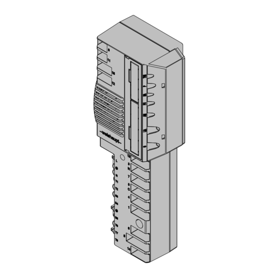
Installation and operating instruction Replacing combustion manager W-FM 20 … 24 with W-FM 25 8 Spares 8 Spares 1.03 1.04 1.01 1.05 1.02 1.06 1.07 1.10 1.08 1.09 1.11 64-70 83294002 • 2/2014-11 • La... - Page 65 Installation and operating instruction Replacing combustion manager W-FM 20 … 24 with W-FM 25 8 Spares Pos. Description Order No. 1.01 Combustion manager W-FM 25 – intermittent operation 600 478 – continuous operation 600 479 1.02 Micro fuse 6.3 AT 722 024 1.03...
-
Page 66: Technical Documentation
Installation and operating instruction Replacing combustion manager W-FM 20 … 24 with W-FM 25 9 Technical documentation 9 Technical documentation 9.1 Program sequence Display Operating phase Condition Fault present F .. OFFUPr UPrGAS Waiting in unprogrammed condition UPrOIL OFFGAS Waiting for heat demand... - Page 67 Installation and operating instruction Replacing combustion manager W-FM 20 … 24 with W-FM 25 9 Technical documentation Display Operating phase Condition Valve proving - test time valve 2 Internal sequence Reference search actuator air damper and gas butterfly valve Test gas butterfly valve actuator 105°...
-
Page 68: Notes
Installation and operating instruction Replacing combustion manager W-FM 20 … 24 with W-FM 25 10 Notes 10 Notes 68-70 83294002 • 2/2014-11 • La... - Page 69 Installation and operating instruction Replacing combustion manager W-FM 20 … 24 with W-FM 25 10 Notes 69-70 83294002 • 2/2014-11 • La...
-
Page 70: Key Word Index
Installation and operating instruction Replacing combustion manager W-FM 20 … 24 with W-FM 25 11 Key word index Program sequence .............66 Access level .................28 Ambient conditions .............13 Reset ..................57 Reset key ................14 Calculation ................29 Consumption ...............13 Contactor ..............31, 57 Safety measures .............. - Page 71 83294002 • 2/2014-11 • La...
- Page 72 Max Weishaupt GmbH · 88475 Schwendi Weishaupt close by? Addresses, telephone numbers etc. can be found at www.weishaupt.de We reserve the right to make changes. All rights reserved. The complete program: Reliable technology and prompt, professional service W Burners up to 570 kW...
Need help?
Do you have a question about the W-FM 25 and is the answer not in the manual?
Questions and answers
oeh/f1h alarm coming. how can i solve this problem