Table of Contents
Advertisement
Quick Links
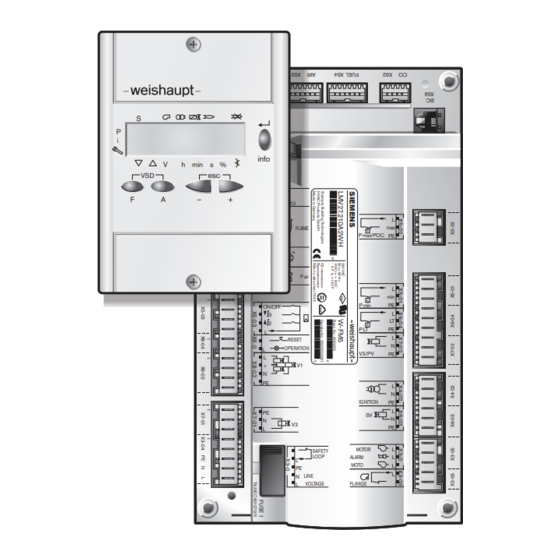
Combustion Manager W-FM 50
Installation and operating instruction
S
P
i
V
h
min
s %
esc
VSD
F
A
–
+
info
FUEL
COUNTER U
PE
ION
QRB/
FLAME
P max/POC
QRB/C-
L
QRA
QRA
P air
L
P min
ON/OFF
3
2
P LT
L
RESET
OPERATION
L
V3/PV
L
V1
•
N
PE
IGNITION
PE
SV
N
V2
L
MOTOR
SAFETY
LOOP
ALARM
L
MOTO
PE
N
LINE
FLANGE
L
VOLTAGE
83250302 1/2018-08
L
max
PE
L
min
PE
L
LT
PE
L
N
PE
L
N
PE
L
N
PE
L
L
L
L
Advertisement
Table of Contents

Related Manuals for Weishaupt W-FM 50


Summary of Contents for Weishaupt W-FM 50
- Page 1 Installation and operating instruction info FUEL – COUNTER U QRB/ FLAME P max/POC QRB/C- P air P min ON/OFF P LT RESET OPERATION V3/PV • IGNITION MOTOR SAFETY LOOP ALARM MOTO LINE FLANGE VOLTAGE Combustion Manager W-FM 50 83250302 1/2018-08...
-
Page 2: Table Of Contents
Installation and operating instruction Combustion Manager W-FM 50 User instructions ...................... 5 1.1 Target group ........................ 5 1.2 Symbols .......................... 5 1.3 Guarantee and Liability .................... 6 Safety ............................. 7 2.1 Designated application .................... 7 2.2 When gas can be smelled .................. 7 2.3 ... - Page 3 Installation and operating instruction Combustion Manager W-FM 50 3.3.5 Analogue output .................... 25 3.4 Technical data ...................... 26 3.4.1 Electrical data ..................... 26 3.4.2 Ambient conditions .................... 26 3.4.3 Dimensions ...................... 27 Installation ........................ 28 4.1 Electrical connection .................... 28 Operation ...
- Page 4 Installation and operating instruction Combustion Manager W-FM 50 Spares .......................... 106 Notes .......................... 108 Key word index ...................... 109 4-112 83250302 1/2018-08 La...
-
Page 5: User Instructions
Installation and operating instruction Combustion Manager W-FM 50 1 User instructions 1 User instructions This manual forms part of the equipment and must be kept on site. Translation of original Carefully read the manual prior to working on the unit. -
Page 6: Guarantee And Liability
Weishaupt parts, force majeure, unauthorised modifications made to the unit, the installation of additional components, which have not been tested with the... -
Page 7: Safety
2 Safety 2 Safety 2.1 Designated application The combustion manager W-FM 50 is suitable for use with single fuel burners. Improper use could: endanger the health and safety of the user or third parties, cause damage to the unit or other material assets. -
Page 8: Gas Supply
Carry out soundness test after each service and fault rectification. 2.4 Alterations to the construction of the equipment All conversions require written approval from Max Weishaupt GmbH. No additional components may be fitted, which have not been tested for use with the equipment. -
Page 9: Product Description
Installation and operating instruction Combustion Manager W-FM 50 3 Product description 3 Product description 3.1 Function 3.1.1 Burner Control A burner control for oil and gas burners is integrated in the combustion manager. It controls the sequence of operation, monitors the flame and communicates with all components. -
Page 10: Valve Proving
Installation and operating instruction Combustion Manager W-FM 50 3 Product description 3.1.3 Valve proving The valve proving gas pressure switch checks if the valves are tight. It signals the combustion manager if the pressure increases or decreases to an impermissible level during valve proving. -
Page 11: Calculation
Installation and operating instruction Combustion Manager W-FM 50 3 Product description 3.1.5 Calculation A calculation can be triggered in modulating commissioning, if P1 and P9 are pro- grammed. During a calculation, a straight line is generated from the operating point displayed to P1 or P9. -
Page 12: Referencing The Actuator
Installation and operating instruction Combustion Manager W-FM 50 3 Product description 3.1.7 Referencing the actuator In operating phase Ph10 (Home Run) the combustion manager references the actuators, whereby the actuator drives over a reference marker. The actuator then drives back and determines the inner edge of the reference marker. All settings are referenced to this position. -
Page 13: Program Sequence
Installation and operating instruction Combustion Manager W-FM 50 3 Product description 3.1.8 Program sequence 3.1.8.1 Operating phase Lockout phase Ph00 Safety phase Ph02 Home run Ph10 Standby Ph12 Fan / safety valve ON Ph22 Pre-purge position Ph24 Pre-purge Ph30 Ignition position... -
Page 14: Gas Direct Ignition
Installation and operating instruction Combustion Manager W-FM 50 3 Product description 3.1.8.2 Gas direct ignition X3-03:1, X3-04:1 X5-03:1 X10-05:2 X3-02:1 X5-01:2 X5-02:2 X9-04:2 X3-05:1 X4-02:3 X6-03:3 X8-02:1 X7-01:3 Signal at input / output actuated No signal on input Input without influence... -
Page 15: Gas With Ignition Pilot Valve
Installation and operating instruction Combustion Manager W-FM 50 3 Product description 3.1.8.3 Gas with ignition pilot valve 74 78 X3-03:1, X3-04:1 X5-03:1 X10-05:2 X3-02:1 X5-01:2 X5-02:2 X9-04:2 X3-05:1 X4-02:3 X6-03:3 X8-02:1 X7-01:3 X7-02:3 Signal at input / output actuated No signal on input... -
Page 16: Fuel Oil El Modulating And Multi-Stage, Heavy Oil Multi-Stage
Installation and operating instruction Combustion Manager W-FM 50 3 Product description 3.1.8.4 Fuel oil EL modulating and multi-stage, heavy oil multi- stage 74 78 X3-03:1, X3-04:1 X5-03:1 X10-05 X3-02:1 X5-01:2 X5-02:2 X3-05:1 X4-02:3 X6-03:3 X8-02:1 X7-01:3 X7-02:3 Only with heavy oil and long pre-ignition phase (parameter 281). -
Page 17: Medium And Heavy Oil Modulating
Installation and operating instruction Combustion Manager W-FM 50 3 Product description 3.1.8.5 Medium and heavy oil modulating 74 78 X3-04:1 X5-03:1 X10-05 X3-02:1 X5-01:2 X5-02:2 X9-04:2 X3-05:1 X4-02:2 X6-03:2 X8-02:1 X7-01:2 X7-02:2 Only for evaluation in operating phase PH38 … PH62 (para- meter 286). -
Page 18: Inputs
Installation and operating instruction Combustion Manager W-FM 50 3 Product description 3.2 Inputs 3.2.1 Voltage supply The voltage supply is connected to inputs X3-04:3-5. The mains frequency is set in parameter 125. 3.2.2 Safety circuit In the diagnostic code, the inputs X3-03:1/2 and X3-04:1/2 are combined as safety circuit. -
Page 19: Minimum Pressure Switch
Installation and operating instruction Combustion Manager W-FM 50 3 Product description 3.2.5 Minimum pressure switch The closing contact of the min. pressure switch is connected to input X5-01. For burners without min. oil pressure switch, a bridge has to be connected to ter- minal 2 and terminal 3. -
Page 20: Valve Proving Gas Pressure Switch
Installation and operating instruction Combustion Manager W-FM 50 3 Product description 3.2.7 Valve proving gas pressure switch The opening contact of the valve proving gas pressure switch is connected to in- put X9-04. Input X9-04 is only activated during valve proving [ch. 3.1.3]. The time of valve proving can be set in parameter 241 . -
Page 21: Flame Sensor
Installation and operating instruction Combustion Manager W-FM 50 3 Product description 3.2.9 Flame sensor If the flame signal in operating phase Ph44 does not correspond to the value re- quired, the combustion manager initiates safety shutdown with restart. If the flame signal during operation does not maintain the required value, the com- bustion manager initiates a controlled shutdown with restart. -
Page 22: Load Controller Analogue Input
Installation and operating instruction Combustion Manager W-FM 50 3 Product description 3.2.10 Load controller analogue input The contact for heat demand is connected to input X5-03:1 (burner ON/OFF). ON/OFF The analogue load signal is connected to terminals X64:1 (4 … 20 mA) and °C X64:2 (GND). -
Page 23: Load Controller Via Contacts
Installation and operating instruction Combustion Manager W-FM 50 3 Product description 3.2.12 Load controller via contacts The contact for heat demand is connected to input X5-03:1 (burner ON/OFF). The load control distinguishes between multi-stage and modulating operation. The operating mode is set in parameter 201 . -
Page 24: Outputs
Installation and operating instruction Combustion Manager W-FM 50 3 Product description 3.3 Outputs 3.3.1 Alarm A mains voltage signal is given at alarm output X3-05:2 in lockout (operating phase MOTOR Ph00). ALARM MOTOR CONT In addition, start prevention can also be signaled. To do this, parameter 210 should be set to 1. -
Page 25: Analogue Output
Installation and operating instruction Combustion Manager W-FM 50 3 Product description 3.3.5 Analogue output Instead of the frequency converter, a load dependent analogue signal can be emit- 24 V ted at output X74:3. Prerequisite is an external 24 V DC voltage source at in- put X74:1/2. -
Page 26: Technical Data
Installation and operating instruction Combustion Manager W-FM 50 3 Product description 3.4 Technical data 3.4.1 Electrical data Combustion Manager Mains voltage / Mains frequency 230 V / 50 … 60 Hz Consumption max 30 W Internal unit fuse T6.3H, IEC 127-2/5... -
Page 27: Dimensions
Installation and operating instruction Combustion Manager W-FM 50 3 Product description 3.4.3 Dimensions Combustion manager 230 mm 217 mm 60 mm Display and operating unit (ABE) Recess dimension: 127 x 91 mm ± 0.5 mm 17 mm 96 mm 18 mm... -
Page 28: Installation
- maximum 20 m (100 pF/m). BCI interface maximum 20 m (100 pF/m). Connecting the burner motor The motor must be protected against thermal overload and short circuit. Weishaupt recommend the use of a motor protection switch. Open terminal box on motor. - Page 29 Installation and operating instruction Combustion Manager W-FM 50 4 Installation Variable speed drive (optional) If the frequency converter is located on the motor, the cable to the frequency con- verter is not screened. If the frequency converter is separate the control line and the motor connection must be screened.
-
Page 30: Operation
Installation and operating instruction Combustion Manager W-FM 50 5 Operation 5 Operation 5.1 Operating interface 5.1.1 Operating panel Display and operating unit (ABE) info [Enter] back-up of value changes; entry to parameter and values [info] call up information press for approx. 3 seconds: Info level press for approx. -
Page 31: Display
Installation and operating instruction Combustion Manager W-FM 50 5 Operation 5.1.2 Display The black cursor in the display shows the status of the inputs and outputs, the unit of values and the active level. 3 4 5 w q 0 9 8 7... - Page 32 Installation and operating instruction Combustion Manager W-FM 50 5 Operation Display OFF The parameter setting is missing, incomplete or has been de- leted. No heat demand from controller (input X5-03:1). Safety circuit not closed at heat demand (input X3-03:1/2 and X3-04:1/2).
-
Page 33: Displaying And Adjusting Parameters
Installation and operating instruction Combustion Manager W-FM 50 5 Operation 5.2 Displaying and adjusting parameters Password level (engineer level) Info-/Service level call up level Press [F] and [A] keys simul- The Info or Service level can only taneously and then enter the be called up from the standard password [ch. 5.2.1]. -
Page 34: Password
Installation and operating instruction Combustion Manager W-FM 50 5 Operation 5.2.1 Password Enter password Press [F] and [A] simultaneously for approx. 2 seconds. The display shows CodE. Enter the first digit using [+] or [–] and confirm with [ENTER]. Repeat procedure until the password has been entered. -
Page 35: Manual Load
Installation and operating instruction Combustion Manager W-FM 50 5 Operation 5.2.2 Manual load If a signal is applied to input X5-03:1 (burner ON), each load setting within the load limit can be selected manually. If manual load is activated, the current load flashing in the operating display. -
Page 36: Parameters
Installation and operating instruction Combustion Manager W-FM 50 5 Operation 5.3 Parameters 5.3.1 Password level Internal parameter (000: Int) Parameter Function Data backup [ch. 3.1.6] Transfer of data sets between W-FM and ABE with identical burner identification (parameter 113). If the backup or restore is incorrect, a negative value is displayed. The cause of the error is described in error code 137 see. - Page 37 Installation and operating instruction Combustion Manager W-FM 50 5 Operation Parameter Function Flame failure test (TÜV test) The flame failure test can only be carried out in operating setting 1 (operating phase Ph60). The flame failure test closes the fuel valves and calculates the time up to flame failure. The calculated time is dis- played in the diagnostic code in multiples of 0.2 seconds (example Loc.D: 8 = 1.6 seconds).
- Page 38 Installation and operating instruction Combustion Manager W-FM 50 5 Operation Parameter Function Replacement load (setting range: 0 … 100 %) Load default for communication failure with building management system. –––: no replacement load 0 … 19.9: burner OFF Number of lockouts Operating hours since last reset Reset: Press [Enter].
- Page 39 Installation and operating instruction Combustion Manager W-FM 50 5 Operation Burner control (200: PAr0) Parameter Function Operating mode ––: not defined (delete curves) 1: Gas direct ignition 2: Gas pilot ignition 5: fuel oil EL, MS and S two stage Z...
- Page 40 Installation and operating instruction Combustion Manager W-FM 50 5 Operation Parameter Function Post burn time Gas (setting range: 0.2 … 60 s) The combustion manager remains in operating phase Ph70 for the duration of the time set, the flame sensor is ignored during this time.
- Page 41 Installation and operating instruction Combustion Manager W-FM 50 5 Operation Parameter Function Minimum oil pressure switch 0: OFF 1: active from operating phase Ph38 2: active from operating phase Ph40 with solenoid valve upstream of pressure switch (e.g. pump with valve) Max. oil pressure switch If a max.
- Page 42 Installation and operating instruction Combustion Manager W-FM 50 5 Operation Parameter Function Activation of frequency converter 0: not activated 1: activated Operating ramp modulating Time for the actuators to drive from low load to high load. Recommended factory setting: 32 s Lower load limit (setting range: 20 … 100 %)
- Page 43 Installation and operating instruction Combustion Manager W-FM 50 5 Operation Parameter Function Activation of the frequency converter with safety circuit open 0: no activation 1: frequency converter is activated with 0 Speed monitoring in standby, standby speed 0 % 0: no speed monitoring 1: speed monitoring activated Fault history (700: HISt)
-
Page 44: Info Level
Installation and operating instruction Combustion Manager W-FM 50 5 Operation Parameter Function Relay nominal condition (Bit coded output) 1: alarm 2: safety valve 4: ignition 8: fuel valve 1 16: fuel valve 2 32: fuel valve 3 / pilot valve... -
Page 45: Service Level
Installation and operating instruction Combustion Manager W-FM 50 5 Operation 5.3.3 Service level In the service level, parameter values can be displayed but not altered. Select parameter using [+] or [-] key. Press [Enter] 1 … 3 s. Parameter value appears. Parameters Function Current flame signal in percent [ch. 3.2.9]... -
Page 46: Commissioning
Installation and operating instruction Combustion Manager W-FM 50 6 Commissioning 6 Commissioning 6.1 Prerequisite Commissioning must only be carried out by qualified personnel. Only correctly carried out commissioning ensures the operational safety. Observe the prerequisites for commissioning in the installation and operating manual of the burner. -
Page 47: Adjusting Gas Side
Installation and operating instruction Combustion Manager W-FM 50 6 Commissioning 6.2.1 Adjusting gas side Prerequisite Open gas isolating valve. Pressure in gas valve train increases. Close isolating valve. Switch on voltage supply. The display shows either OFF UPr or OFF. - Page 48 Installation and operating instruction Combustion Manager W-FM 50 6 Commissioning 3. Start setup Press [ENTER]. If the combustion manager has been pre-programmed, the display shows run 1. Select type of setting (from step 9). If the combustion manager has not been programmed, the display shows parameter 201 2.
- Page 49 Installation and operating instruction Combustion Manager W-FM 50 6 Commissioning 5. Activate/deactivate frequency converter Press [+] key. The display shows parameter 542. Press [Enter]. The display shows only the parameter value. Activate or deactivate the frequency converter using [+] or [–] and confirm with [ENTER].
- Page 50 Installation and operating instruction Combustion Manager W-FM 50 6 Commissioning 7. Preset ignition load point Press [+] key. The display shows the ignition load point P0. press and hold [A] and using [+]/[–] set air damper setting 4.0 … 9.0. Press and hold [F] and set gas butterfly valve setting 8.0 … 13.0° using [+]/[–].
- Page 51 Installation and operating instruction Combustion Manager W-FM 50 6 Commissioning 9. Select type of setting The following can be selected as type of setting: Adjustment with flame Pre-setting without flame Pre-setting without flame is only used, if the operating points are known, for ex- ample if the combustion manager is exchanged.
- Page 52 Installation and operating instruction Combustion Manager W-FM 50 6 Commissioning 10. Pre-set points without flame This step must only be carried out, if the type of setting without flame has been se- lected previously. The adjustment with flame (from step 11) is not replaced by this process.
- Page 53 Installation and operating instruction Combustion Manager W-FM 50 6 Commissioning Exit pre-setting using [esc]. The display shows 400 SEt. Press [ENTER]. The display shows run. Press [ENTER]. Check rotation direction of burner motor The burner starts pre-purge and stops in ignition position without flame forma- tion.
- Page 54 Installation and operating instruction Combustion Manager W-FM 50 6 Commissioning 12. Check gas valves Press [+] key and ensure that the valves open and close correctly. The burner attempts to ignite. The low gas pressure switch reacts. After the interruption, the display shows OFF UPr.
- Page 55 Installation and operating instruction Combustion Manager W-FM 50 6 Commissioning 16. Pre-set operating point P1 Press [+] key. The display shows the operating point P1. Pre-set gas throughput [F] and air quantity [A] whilst observing combustion val- ues. Operating point P1 must lie below the partial load required and within the capa- city graph.
- Page 56 Installation and operating instruction Combustion Manager W-FM 50 6 Commissioning 17. Drive to full load Using the [+] key, drive to the points in sequence up to P9. Check combustion values at each point and if necessary correct via the gas but- terfly valve setting [F].
- Page 57 Installation and operating instruction Combustion Manager W-FM 50 6 Commissioning 19. Re-define point 1 (only for ZMI) This step should only be carried out on burners in version ZMI. On burners of differ- ent version, skip this step and proceed with step 20.
- Page 58 Installation and operating instruction Combustion Manager W-FM 50 6 Commissioning 20. Initiate a calculation To achieve a constant operating behaviour, it is necessary to initiate a calculation from P9 to P1. Press [–] for approx. 4 seconds. The display shows CALC. Release [–] key.
- Page 59 Installation and operating instruction Combustion Manager W-FM 50 6 Commissioning 22. Define upper load limit (full load) Full load can be limited via parameter 546 . Exit setting mode using [esc]. The display shows 546 – – – –. Full load has not been defined, that means full load ≙...
- Page 60 Installation and operating instruction Combustion Manager W-FM 50 6 Commissioning 24. Save points Exit level using [esc]. The display shows 400 SEt. Exit entry using [esc]. The display shows oP (Operate) with the current rating. 25. Check start behaviour Switch off and restart burner.
-
Page 61: Adjust Modulation Oil Side
Installation and operating instruction Combustion Manager W-FM 50 6 Commissioning 6.2.2 Adjust modulation oil side Prerequisite Open oil shut off devices. Switch on voltage supply. The display shows either OFF UPr or OFF. burner off and not programmed OFF UPr burner off 1. - Page 62 Installation and operating instruction Combustion Manager W-FM 50 6 Commissioning 3. Start setup Press [ENTER]. If the combustion manager has been pre-programmed, the display shows run 1. Select type of setting (from step 9). If the combustion manager has not been programmed, the display shows parameter 201 2.
- Page 63 Installation and operating instruction Combustion Manager W-FM 50 6 Commissioning 5. Activate/deactivate frequency converter Press [+] key. The display shows parameter 542. Press [Enter]. The display shows only the parameter value. Activate or deactivate the frequency converter using [+] or [–] and confirm with [ENTER].
- Page 64 Installation and operating instruction Combustion Manager W-FM 50 6 Commissioning 7. Preset ignition load point Press [+] key. The display shows the ignition load point P0. The ignition load point P0 is factory preset, see burner data sheet. If values are available proceed with step 8.
- Page 65 Installation and operating instruction Combustion Manager W-FM 50 6 Commissioning 8. Preset full load point Press [+] key. The display shows the full load point P9. Press and hold [A] and using [+]/[–] set air damper setting from setting diagram, see burner installation and operating manual.
- Page 66 Installation and operating instruction Combustion Manager W-FM 50 6 Commissioning 9. Select type of setting The following can be selected as type of setting: Adjustment with flame Pre-setting without flame Pre-setting without flame is only used, if the operating points are known, for ex- ample if the combustion manager is exchanged.
- Page 67 Installation and operating instruction Combustion Manager W-FM 50 6 Commissioning 10. Pre-set points without flame This step must only be carried out, if the type of setting without flame has been se- lected previously. The adjustment with flame (from step 11) is not replaced by this process.
- Page 68 Installation and operating instruction Combustion Manager W-FM 50 6 Commissioning Exit pre-setting using [esc]. The display shows 400 SEt. Press [ENTER]. The display shows run. Press [ENTER]. Check rotation direction of burner motor The burner starts pre-purge and stops in ignition position without flame forma- tion.
- Page 69 Installation and operating instruction Combustion Manager W-FM 50 6 Commissioning 12. Check pump pressure The pump pressure in ignition position must be approx. 1 … 2 bar less than that of the full load pressure, see burner data sheet. Check pump pressure at pressure gauge.
- Page 70 Installation and operating instruction Combustion Manager W-FM 50 6 Commissioning 15. Pre-set operating point P1 Only in conjunction with frequency converter In oil operation, the speed should only be reduced so far, that the pump pressure set at full load does not fall by more than 15 %.
- Page 71 Installation and operating instruction Combustion Manager W-FM 50 6 Commissioning 17. Adjust full load When adjusting, the ratings data given by the boiler manufacturer and the capacity graph of the burner should be observed. Only in conjunction with frequency converter Select speed at full load as low as possible, but not less than 80 %.
- Page 72 Installation and operating instruction Combustion Manager W-FM 50 6 Commissioning 19. Adjusting the operating points If the [–] key is pressed again for more than 4 seconds, a calculation is started from the point shown to P1. Briefly press [–] key, to ensure points calculated or set are not overwritten.
- Page 73 Installation and operating instruction Combustion Manager W-FM 50 6 Commissioning 21. Define lower load limit (partial load) Partial load can be limited via parameter 545. When adjusting, the ratings data given by the boiler manufacturer and the capacity graph of the burner should be observed.
- Page 74 Installation and operating instruction Combustion Manager W-FM 50 6 Commissioning 24. Carry out data backup Press keys [F] and [A] simultaneously. Select 000: Int using [-] key and confirm with [ENTER]. The display shows parameter 050.00: 0 Press [Enter]. The display shows bAC_up.
-
Page 75: Adjust Multi-Stage Oil Side
Installation and operating instruction Combustion Manager W-FM 50 6 Commissioning 6.2.3 Adjust multi-stage oil side Only in conjunction with frequency converter When using a frequency converter please note: Ignition speed and speed in full load should be 100 %. It is recommended that the speed at the on and off switch points is 100 %. - Page 76 Installation and operating instruction Combustion Manager W-FM 50 6 Commissioning 3. Start setup Press [ENTER]. If the combustion manager has been pre-programmed, the display shows run 1. Select type of setting (from step 9). If the combustion manager has not been programmed, the display shows parameter 201 2.
- Page 77 Installation and operating instruction Combustion Manager W-FM 50 6 Commissioning 5. Activate/deactivate frequency converter Press [+] key. The display shows parameter 542. Press [Enter]. The display shows only the parameter value. Activate or deactivate the frequency converter using [+] or [–] and confirm with [ENTER].
- Page 78 Installation and operating instruction Combustion Manager W-FM 50 6 Commissioning 7. Preset ignition load point Only in conjunction with frequency converter The ignition speed should be 100 %. Press and hold [A] and [F] (VSD) simultaneously and set speed to 100 % us- ing [+]/[–] key.
- Page 79 Installation and operating instruction Combustion Manager W-FM 50 6 Commissioning 8. Select type of setting The following can be selected as type of setting: Adjustment with flame Pre-setting without flame Pre-setting without flame is only used, if the operating points are known, for ex- ample if the combustion manager is exchanged.
- Page 80 Installation and operating instruction Combustion Manager W-FM 50 6 Commissioning 9. Pre-set points without flame This step must only be carried out, if the type of setting without flame has been se- lected previously. The adjustment with flame (from step 10) is not replaced by this process.
- Page 81 Installation and operating instruction Combustion Manager W-FM 50 6 Commissioning 10. Check mixing pressure in ignition position The mixing pressure in ignition position must be 2 … 5 mbar above the combustion chamber pressure. If necessary, adjust mixing pressure via air damper setting: 11.
- Page 82 Installation and operating instruction Combustion Manager W-FM 50 6 Commissioning 12. Igniting the burner Press [+] key. The burner starts and stops in ignition position. The display shows the following operating phases: PH 38: Ignition ON PH 40: Fuel valve Ph 42: Ignition OFF PH 44: Flame in ignition position...
- Page 83 Installation and operating instruction Combustion Manager W-FM 50 6 Commissioning 15. Set pre-set point P2_d Press [+] key. The display shows the pre-set point P2_d. Valve operating point 2 remains closed. Pre-set air damper setting [A] expected for the operating point P2 .
- Page 84 Installation and operating instruction Combustion Manager W-FM 50 6 Commissioning 18. Initiate partial load Press [–] key. The display shows switch point P3oF. The switch point determines, at which air damper setting the valve of the stage above closes. The point itself can not be activated.
- Page 85 Installation and operating instruction Combustion Manager W-FM 50 6 Commissioning 21. Check start behaviour Switch off and restart burner. Check start behaviour and if necessary: correct ignition position, increase oil temperature at oil preheater. If the ignition position has been altered: Re-check start behaviour.
-
Page 86: Check Combustion
Installation and operating instruction Combustion Manager W-FM 50 6 Commissioning 6.3 Check combustion Determine excess air Slowly close air damper(s) in the relevant operating point, until the combustion limit is reached (CO content approx. 100 ppm or smoke number approx. 1). -
Page 87: Calculate Gas Throughput
Installation and operating instruction Combustion Manager W-FM 50 6 Commissioning 6.4 Calculate gas throughput Formula symbol Explanation Example values Operating volume [m – Volume measured at gas meter at current pressure and temperature (gas throughput). Standard volume [m – Volume gained by gas at 1013 mbar and 0 °C. -
Page 88: Servicing
The design lifespan of the components is listed in the service plan [ch. 7.2]. Weishaupt recommends a service contract is entered into to ensure regular in- spections. -
Page 89: Service Plan
Installation and operating instruction Combustion Manager W-FM 50 7 Servicing Following servicing Check tightness of oil and gas carrying components. Check function of: adjustable mixing head, ignition, flame monitoring, gas carrying components (gas connection pressure and setting pressure), oil pump (pump pressure and suction resistance), pressure switch Check control and safety devices. -
Page 90: Troubleshooting
Low water safety interlock on heat ex- Top up water. changer has triggered Reset low water safety interlock on heat exchanger. Notify your heating contractor or Weishaupt Customer Service if the problem occurs repeatedly. 90-112 83250302 1/2018-08 La... -
Page 91: Lockout
Installation and operating instruction Combustion Manager W-FM 50 8 Troubleshooting 8.1.3 Fault If a fault occurs, the combustion manager initiates a controlled shutdown. The display and operating unit alternates between Err.c: (error code) and Err.d: (diagnostic code). The burner restarts automatically as soon as the fault condition has been rectified. -
Page 92: Fault History
Installation and operating instruction Combustion Manager W-FM 50 8 Troubleshooting 8.2 Fault history The combustion manager stores the last 25 faults and lockouts in the fault history (parameter 700), 701 is the fault, which occurred last. The fault history can be called up in the service level or password level. - Page 93 Installation and operating instruction Combustion Manager W-FM 50 8 Troubleshooting Delete faults Only the fault history in the service level can be deleted. The fault history in the password level is not affected by the deleting process. Enter password [ch. 5.2.1].
-
Page 94: Rectifying Faults
Installation and operating instruction Combustion Manager W-FM 50 8 Troubleshooting 8.3 Rectifying faults Fault code Diagnostic Cause Rectification codes No flame signal in operating phase Ph44 Check flame sensor (soiled, defective, signal strength…) No flame signal in operating phase Ph52... - Page 95 Installation and operating instruction Combustion Manager W-FM 50 8 Troubleshooting Fault code Diagnostic Cause Rectification codes Current load incorrect – Target load incorrect – Target position incorrect – Different positions reached Repeat standardisation Internal fault Replace combustion manager if fault...
- Page 96 Installation and operating instruction Combustion Manager W-FM 50 8 Troubleshooting Fault code Diagnostic Cause Rectification codes Ramp time during run down during stand- Increase ramp time (parameter 523). ardisation too short Standardised speed not saved Repeat standardisation No speed signal...
- Page 97 Installation and operating instruction Combustion Manager W-FM 50 8 Troubleshooting Fault code Diagnostic Cause Rectification codes Speed not achieved, lower control limit Rectification see error code 80. was activated Speed not achieved, upper control limit Rectification see error code 80.
- Page 98 Installation and operating instruction Combustion Manager W-FM 50 8 Troubleshooting Fault code Diagnostic Cause Rectification codes Position error air actuator Check, if actuator is blocked. Air actuator line break min 0.5 V between Pin 5 and 2 or 6 and Check wiring...
- Page 99 Installation and operating instruction Combustion Manager W-FM 50 8 Troubleshooting Fault code Diagnostic Cause Rectification codes Internal fault contact interrogation Can be caused by capacitive loads or dir- ect current feed at the inputs. The input, at Minimum pressure switch which the fault occurred is displayed with Max.
- Page 100 Installation and operating instruction Combustion Manager W-FM 50 8 Troubleshooting Fault code Diagnostic Cause Rectification codes Aborted due to Time-out during Backup / Check the connection 255 (-1) Restore or ABE does not have this func- Repeat Backup / Restore.
- Page 101 Installation and operating instruction Combustion Manager W-FM 50 8 Troubleshooting Fault code Diagnostic Cause Rectification codes Manual lockout by contact No fault Manual lockout by ABE – Manual lockout by PC-Tool Communication between W-FM and ABE – was interrupted during curve setting Communication between W-FM and PC- –...
-
Page 102: Technical Documentation
Installation and operating instruction Combustion Manager W-FM 50 9 Technical documentation 9 Technical documentation 9.1 Frequency converter Detailed information see Frequency converter CD. The construction and arrangement of diagnostic LEDs is dependent on the size of the frequency converter. 9.1.1 Frequency converter Nord size I … III... - Page 103 Installation and operating instruction Combustion Manager W-FM 50 9 Technical documentation Diagnostic LED's Signal Description 1 (BUS-S) – System bus status (not used) 2 (BUS-E) – System bus fault (not used) 3 (DS) No mains voltage and no control voltage...
-
Page 104: Frequency Converter Nord Size Iv
Installation and operating instruction Combustion Manager W-FM 50 9 Technical documentation 9.1.2 Frequency converter Nord size IV 1 Interfaces 2 Diagnostic LED's 3 Status LED's Interface The interface is used to access the frequency converter via a PC. The Software required can be found on the Frequency Converter CD. - Page 105 Installation and operating instruction Combustion Manager W-FM 50 9 Technical documentation Status LED's Signal Description A (AS-i) – Status AS interface (not used) B (DS) No mains voltage and no control voltage Green Operation, FC operating Green ON + Frequency converter not ready for oper-...
-
Page 106: Spares
Installation and operating instruction Combustion Manager W-FM 50 10 Spares 10 Spares 1.01 1.03 1.04 1.02 106-112 83250302 1/2018-08 La... - Page 107 Installation and operating instruction Combustion Manager W-FM 50 10 Spares Pos. Description Order No. 1.01 ABE for W-FM 50/54 600 408 1.02 Plug cable ABE-W-FM 50 – 2 m 400 406 – 10 m 600 407 1.03 Combustion manager W-FM50 230 V 50/60 Hz 600 402 1.04...
-
Page 108: Notes
Installation and operating instruction Combustion Manager W-FM 50 11 Notes 11 Notes 108-112 83250302 1/2018-08 La... -
Page 109: Key Word Index
Installation and operating instruction Combustion Manager W-FM 50 12 Key word index 12 Key word index Extraneous light .............. 21 ABE .................. 26 Actuator................. 43 Air actuator ................ 41 Fan motor................ 24 Air number ................ 86 Fan run-up time .............. 39 Air pressure ................ 87 Fault .................. 90 Air pressure switch............. 18 Fault code................ - Page 110 Installation and operating instruction Combustion Manager W-FM 50 12 Key word index Ionisation electrode ............ 21 Point of ignition.............. 41 Post burn time .............. 40 Post-purge position............ 41 Post-purge time.............. 40 Liability.................. 6 Pre-ignition phase.......... 16, 17, 24 Lifespan................ 7, 88 Pre-purge................ 39 Limit switch................ 18 Pre-purge position............ 39, 41 Load change ................ 36...
- Page 111 Installation and operating instruction Combustion Manager W-FM 50 12 Key word index Two stage .............. 22, 39 Type of operation .............. 39 Type of protection............... 26 Unit address................. 37 UV cell ................... 21 Valve proving.............. 10, 20 Valve proving gas pressure switch ......... 20 Valve proving pressure switch ......... 20 Voltage supply .............. 18...
- Page 112 Max Weishaupt GmbH · 88475 Schwendi Weishaupt close by? Addresses, telephone numbers etc. can be found at www.weishaupt.de We reserve the right to make changes. All rights reserved. The complete program: Reliable technology and prompt, professional service W Burners up to 570 kW...
Need help?
Do you have a question about the W-FM 50 and is the answer not in the manual?
Questions and answers