GFA TS 971 Installation Instructions Manual
Door control. automatic control panel with radio.
Hide thumbs
Also See for TS 971:
- Operating instructions manual (64 pages) ,
- Installation instructions manual (53 pages) ,
- Manual (49 pages)

Related Manuals for GFA TS 971


Summary of Contents for GFA TS 971
- Page 1 Installation instructions Door control TS 971 Automatic control panel with radio Version: 51171521 -en- Version: i / 04.2019 0 0 0 0 0 0 0 0 0 0 0 5 1 1 7 1 5 2 1 XXXXX...
- Page 2 GfA ELEKTROMATEN GmbH & Co. KG Wiesenstraße 81 • 40549 Düsseldorf www.gfa-elektromaten.de info@gfa-elektromaten.de...
-
Page 3: Table Of Contents
Contents General safety information ....................6 Technical data ........................ 7 Mechanical installation ....................8 Electrical installation ....................... 9 Connection cable connection overview ................10 Limit switch configuration, screwable version up to year of construction in 1997 .... 11 Limit switch configuration, single limit switches ............... 11 Carrying out the electrical installation................ - Page 4 Door safety switch on "WSD" door module ..............22 Teach-in of WSD door-module ..................23 Completing the advanced electrical installation ............... 23 Control programming ....................24 Table menu items ......................25 Door operating modes ..................... 25 Door positions ......................... 26 Door functions, ........................
- Page 5 X20 / X21: Potential-free relay contacts ................55 Force monitoring (DES only) ................... 55 Travel time monitoring (NES only) .................. 56 UBS system ........................57 UBS connection ......................57 Reversing duration adjustment ..................57 Maintenance cycle counter ..................... 58 Short-circuit/overload display ..................58 Display for active WSD door-module wireles safety device ..........
-
Page 6: General Safety Information
1 General safety information Specified use The door control is intended for a power-operated door with a drive unit (NES/DES GfA limit switch system). The safe operation is only guaranteed with specified normal use. The drive unit is to be protected from rain, moisture and aggressive ambient conditions. -
Page 7: Technical Data
93 % Protection class of housing with CEE-plug IP 54 / IP 65 Protection class of housing IP 65 NES (mechanical limit switch) Compatible GfA - limit switch DES (digital limit switch) 2.4 GHz Integrated radio receiver Radio 434 MHz... -
Page 8: Mechanical Installation
3 Mechanical installation Control installation! Indoor use only Mounting only on even ground that is free of vibration Only vertical mounting position allowed Door must be in clear view from place of installation Requirements The permissible loads on walls, mountings, connection and transmission elements must not be exceeded. -
Page 9: Electrical Installation
4 Electrical installation Warning - Danger to life due to electrical current! Disconnect the cables (mains OFF) and check that the supply is off Observe the applicable regulations and standards Ensure proper electrical connection Use suitable tools On-site backup fuse and mains disconnector! ... -
Page 10: Connection Cable Connection Overview
Connection cable connection overview Ⓐ Ⓑ Ⓒ Ⓓ DES → X12 DES MOT → Core Description: Core Term. Description: ① 5/wh ① +24 V safety circuit ① Phase W ② 6/bn ② Channel B (RS485) ② Phase V ③ 7/gn ③... -
Page 11: Limit Switch Configuration, Screwable Version Up To Year Of Construction In 1997
Limit switch configuration, screwable version up to year of construction in 1997 4 (N) Thermal contact Limit switch board Rectifier Emergency OPEN limit switch Motor Emergency CLOSE limit switch Emergency manual operation OPEN limit switch Connection cable CLOSE limit switch Spring-loaded brake Auxiliary limit switch Auxiliary limit switch... -
Page 12: Carrying Out The Electrical Installation
Carrying out the electrical installation ▶ Remove covers. ▶ Open cable entry ① or ②. ▶ Insert and connect connection cable in the open cable entry ① (from below) or ② (from above). ▶ Properly tighten cable glands. Avoid damage to parts! ... -
Page 13: Mains Supply
Mains supply 3~, N, PE 3~, PE 1~, N, PE, sym. 1~, N, PE, asym. 220 – 400 V 220 – 400 V 220 – 230 V 220 – 230 V 50 - 60 Hz 50 - 60 Hz 50 - 60 Hz 50 - 60 Hz L1 L2 L3 N PE L1 L2 L3... -
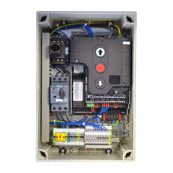
Page 14: Overview Of Control
Overview of control DES/ F1 = 1,6A t 24 V mains supply, external devices DES/ DES or NES limit switch socket Mains supply Micro-fuse 1.6 A time-lag Safety edge and door safety switch Motor socket Selector switch Emergency STOP control device OPEN push-button Automatic closing On/Off STOP push-button... -
Page 15: Starting Up The Control
5 Starting up the control ▶ Supply cables Insert / switch on DES: Rapid adjustment of final limit positions When using a light curtain with OSE signal output (connection to terminal X2), please note menu item 0.3 first. 1. Check output rotating direction 2. -
Page 16: Nes: Rapid Adjustment Of Final Limit Positions
Observe the installation instructions of the drive unit! For adjusting the mechanical limit switch, see the drive unit installation instructions NES: Rapid adjustment of final limit positions When using a light curtain with OSE signal output (connection to terminal X2), please note menu item 0.3 first. -
Page 17: Advanced Electrical Installation
6 Advanced electrical installation Fehler! Verweisquelle konnte nicht gefunden werden. Connection of spiral cable / Light curtain X2 Electrical safety edge Junction box ST+ Mains supply Input for door safety switch Input electrical safety edge Electrical safety edge End of line resistor (8k2) Door control socket Pneumatic safety edge Junction box... -
Page 18: Door Safety Switch / Crash Switch X2
Emergency stop X3 Door safety switch / Crash switch X2 A18/A19 A18/A19 A18/A19 S30/ A18 / A19 Junction box A20 Junction box switch A21 Junction box switch A22 Junction box switch Pass-door switch Crash switch Crash switch (NC contact) (NC contact) (NO contact) Slack-rope switch (NC contact) -
Page 19: External Control Device X5
External Control device X5 External Control device X5 Three push button A4 Key push-button A6 Three push button Photo cell X6 Photo cell X6 1 2 3 4 5 1 2 3 4 5 A8 Reflective Through-beam Through-beam photo cell photo cell photo cell Transmitter... -
Page 20: Radio Receiver X7
Radio receiver X7 Pull switch X7 Intermediate open X8 Radio receiver X7 Pull switch X7 Intermediate open X8 1 2 3 4 Red/green traffic lights X20 / X21 Magnetic brake X20 / X21 Red/green traffic lights X20 / X21 Magnetic brake X20 / X21 X20/ X20/ H1 Traffic light, green... -
Page 21: Wsd Door-Module (Wireless Safety Device)
WSD door-module (Wireless Safety Device) WSD door-module (Wireless Safety Device) Direction for opening ⑥ A23 WSD door module ST2 Socket for system-2 connection cable ① ⑦ WSD door-module push-button Safety edge evaluation switch: ② Switch “A” for system 1, switch “B” for system 2 ... -
Page 22: Optical Safety Edge Ose System 2 To Wsd Door-Module
Optical safety edge OSE System 2 to WSD door-module Optical safety edge OSE System 2 to WSD door-module A23 WSD door module A24 System 2 end box Door safety switch on "WSD" door module Door safety switch on "WSD" door module A24 System 2 end box X1 / X2... -
Page 23: Teach-In Of Wsd Door-Module
Teach-in of WSD door-module Teach-in of WSD door-module Depassivate battery and insert Supply cables insert / switch on Activate Channel 8, for example Available channels Teach in WSD door-module connected, dot on right is lit Note! Use of a safety edge only possible via menu item 0.1, door operating mode “.3”, “.4”... -
Page 24: Control Programming
7 Control programming 1. Start programming Note! Complete programming is only possible after setting the final limit positions 2. Select menu item and confirm 3.a) Set and store functions 3.b) Set and store positions (DES) 4. Exit programming... -
Page 25: Door Operating Modes
8 Table menu items Door operating modes Door operating modes Door operating mode Hold-to-run OPEN Hold-to-run CLOSE Self-hold OPEN Hold-to-run CLOSE Self-hold OPEN Self-hold CLOSE Self-hold OPEN / CLOSE Self-hold, CLOSE hold-to-run release via external X5 control device Hold-to-run OPEN Hold-to-run CLOSE with active safety edge Output rotating direction Maintain output rotating direction... -
Page 26: Door Positions
Door positions Door positions OPEN final limit position, coarse correction (DES) Approach and store desired door position CLOSE final limit position, coarse correction (DES) Approach and store desired door position OPEN final limit position, fine correction (DES) Without door movement, [ + ] OPEN correction [ –... -
Page 27: Door Functions
Door functions, Door functions, part 1 Safety device Spiral cable Teach-in of WSD door-module wireless safety device .2 to 4.0: Manual channel selection Up to 39 doors: Do not assign any radio channel twice. If more than 39 doors: Ensure maximum distance between the door controls with the same channels. - Page 28 Door functions, Part 2 Automatic closing 1 to 99 seconds 100 to 199 seconds 200 to 240 seconds Reaction of automatic closing to photo cell / light curtain Stopping of automatic closing and CLOSE command Vessel recognition Stopping of automatic closing and CLOSE command when actuated for >1.5 seconds Reverse in case of obstacle Off (recommended for light curtains)
- Page 29 Door functions, Part 3 Relay function on X20 Relay function on X21 Impuls contact for 1 second Permanent contact Red lamp, permanently lit during door movement OPEN final limit position Flashing for 3 seconds CLOSE final limit position Flashing for 3 seconds Red lamp, permanently lit during door movement OPEN final limit position Flashing for 3 seconds...
- Page 30 Door functions, Part 4 Intermediate open function All command inputs Input X7.2 and internal radio receiver Input X5.3 and OPEN push-button of control...
-
Page 31: Safety Functions
Safety functions Safety functions Force monitoring (DES) 0 = Off Adjustable for 2 % to 10 % overload Interruption of the photo cell function (DES) (single reference position taught-in twice) Travel time monitoring (NES) 0 = Off 1 to 90 seconds Door safety switch function (Input X2.2 / WSD door-module) Slack-rope or pass-door switch... -
Page 32: Di/Fi Settings
DI/FI settings DI/FI settings OPEN output speed Output speed in rpm CLOSE output speed When a safety device is triggered, the door moves at reduced speed. Output speed in rpm Increased CLOSE output speed Up to an opening height of 2.5 m When a safety device is triggered, the door moves at reduced speed. -
Page 33: Extended Door Functions
Selection of radio transmitters manufacturer (434 MHz) Internal radio receiver deactivated (Fixcode) GfA, Tedsen Teleco "COD1" (Rolling code of various providers) GfA UK, JCM, Dickert (Fixed code) RDA Radio receiver function Teach-in of a handheld transmitter Cancellation of a taught-in handheld transmitter... -
Page 34: Maintenance Cycle Counter
Maintenance cycle counter Maintenance cycle counter Maintenance cycle preselection 01-99 corresponds to 1,000 to 99,000 cycles Cycles are counted down Reaction upon reaching "Zero" Status indication "CS" appears in turns with value set by menu item 8.5. Changeover to "Hold-to-run" door operating mode. Status indication "CS" appears in turns with value set by menu item 8.5. -
Page 35: Readout Of Data Memory
The software version of the control is displayed. For direct inverter or frequency inverter drive units, the software version of the motor is displayed as well. Deleting / readout Deleting / readout Deleting of all settings Activating GfA stick All settings are set to factory setting! Except for cycle counter... -
Page 36: Reading Out Wsd Door-Module Data
Reading out WSD door-module data Reading out WSD door-module data WSD door-module data (Only activated at taught-in WSD door-module, Displaying of missing data is done by „-.-.“) Data indicated alternately 1. Version of master radio module 2. Type of safety edge „0.0.“... -
Page 37: Safety Devices
9 Safety devices X2: Input, door safety switch function The door safety switch is installed on the door and connected to the door control via the spiral cable. Menu item 3.4: Function Reaction upon activation Switching contact is interrupted: Door stop ".1"... - Page 38 Slack-rope/Pass-door If the pass-door switch is open circuit when an open or close command is given, fault F1.2 is displayed. If activated during the door movement, the door is immediately stopped and fault F1.2 is displayed. Entrysense (electronic pass-door switch) The pass-door switch, which has been tested to performance level c (plc) in accordance with EN 13849-1, is monitored by the door control.
-
Page 39: X2: Input For Safety Devices
X2: Input for safety devices The door control detects three different safety edges automatically. Alternatively, a light curtain can be connected. Important! Connect safety edge systems in accordance with EN 12978 "Hold-to-run" door operating mode can always be used should the safety edge be defective Electrical safety edge The input is meant for an electrical safety edge (NO) with a terminal resistance of 8k2 (+/-5 %... -
Page 40: Installation Of The Spiral Cable
Light curtain The light curtain detects people and obstacles without contact. If a light beam from the light curtain is interrupted, the door moves to final limit position OPEN. When the light beam is interrupted, fault indication F4.6 appears. When using a light curtain, menu item 0.3 must be set to function ".2"... - Page 41 Note: Ground adjustment! Automatic compensation of rope elongations or changes in ground conditions of approx. 2-5 cm With DES limit switch only Do not use with overrun correction Do not use with pressure-wave switch or light curtain. Note: Reversing upwards in the overrun area! ...
- Page 42 Function: Reverse in case of obstacle Menu item 2.5 extends menu item 2.3: Menu item 2.3 (automatic closing) allows the door to close automatically after a pre-set time has elapsed. If an obstacle is in the door movement path during the closing process (safety device is triggered), the door stops the closing attempt and then moves back to its starting position.
-
Page 43: Integrated Wsd Door-Module
The signals of the safety edge are transmitted by radio to the door control. The radio receiver is integrated as standard in door control TS 971. Commissioning via "Teach-in of the WSD door-module". Attention – Damage to components! ▶... - Page 44 Note! ▶ For a description of the safety device and relevant adjustment procedures see X2 Crash switch function as NO contact is hidden If the battery is low, fault indication F1.9 appears and there is a changeover to the "Hold-to-run"...
-
Page 45: Emergency Operation
EMERGENCY operation Warning! ▶ For EMERGENCY operation, the door has to be checked (it has to be in a fault- free state) “Hold-to-run” door operating mode: The door must be fully visible from the operating point EMERGENCY operation allows for moving the door to a required position by bypassing faults with the signal transmission of the safety device. -
Page 46: Functional Description
10 Functional description X: 24 VDC voltage supply Connection of external devices such as photo cell, radio receiver, relay, etc. via the 24 V and GND terminals. Attention – Damage to components! Total current consumption of external devices: maximum 350 mA X1: Mains supply of the control and supply of external devices Mains supply of the control Connection via the terminals X1/1.1 to X1/1.4 and PE. -
Page 47: X4: Input, Automatic Closing Off/On
X4: Input, automatic closing Off/On Connection of a switch via the terminals X4/1 and X4/2 for switching the automatic closing off and on. X5: Input, control device Warning! ▶ "Hold-to-run" door operating mode: The door must be fully visible from the operating point The door operating mode ".3"... -
Page 48: X6: Input "Through / Reflective Photo Cell" Resp. Light Curtain
X6: Input "Through / reflective photo cell" resp. light curtain Photo cell A photo cell is used for presence detection. It is only active in door operating modes ".3" and ".4", in the OPEN final limit position or during the CLOSE-operation. If the light beam is interrupted, fault indication F2.1 appears. - Page 49 Reaction to interrupting of light beam Door position Reaction to interrupting of light beam CLOSE final limit position No action OPEN-operation No action OPEN final limit position No action Without automatic closing OPEN final limit position Reset automatic closing With automatic closing OPEN final limit position ...
- Page 50 Disconnection of photo cell function (only DES) Menu item 3.2 Function Disconnection of photo cell function ".0" ".1" The teach-in mode gets activated after exiting the programming. Warning! Presence detection is disabled in the teach-in mode In the teach-in mode, the door must be fully opened and closed twice. The light beam must be interrupted twice at the same door position.
-
Page 51: X7: Input Pull Switch/Radio Receiver
X7: Input pull switch/radio receiver Connection of a pull switch or external radio receiver via the terminals X7/1 and X7/2. The switching contact must be potential-free (NO contact). Pull switch or radio receiver function Menu item 2.6: Type of impuls Reaction upon activation ... -
Page 52: Internal Radio Receiver
Internal radio receiver The integrated radio receiver can be set for a specific radio transmitter manufacturer via menu item 7.6. Handheld transmitters can be taught or deleted via menu item 7.7. Note! A combination of different radio transmitter manufacturers is possible ... -
Page 53: Deleting An Individual Radio Transmitter
Deleting an individual radio transmitter Deleting an individual radio transmitter 1. Activate delete, 10 seconds active 2. Delete 3. Switch to door operation Deleting all radio transmitters Deleting all radio transmitters 1. Delete all channels 2. Switch to door operation... -
Page 54: X8: Input, Intermediate Stop On/Off
X8: Input, intermediate stop On/Off Connect a switch to terminals X8/1 and X8/2 to activate and deactivate the intermediate open. The intermediate open position muss be programmed via menu item 1.6. With an OPEN command, the door moves to the stored door position. When the Intermediate open function is deactivated, the door can move back to the OPEN final limit position. -
Page 55: X20 / X21: Potential-Free Relay Contacts
X20 / X21: Potential-free relay contacts The relay functions are described under menu item 2.7 / 2.8. Attention – Damage to components! Maximum electrical current of 1 A at 230 V AC and 0.4 A at 24 V DC ... -
Page 56: Travel Time Monitoring (Nes Only)
After exiting programming, the door must carry out a full OPEN and CLOSE-operation in self- hold mode. The force monitoring is a self-learning system which is effective for an opening gap of 5 cm to 2 m (approx.). Slow progressive changes, e.g. gradual reduction of the spring torsion, are compensated automatically. -
Page 57: Ubs System
UBS system The UBS system is a simple plug-in connection technology from GfA. The control devices are connected to the control by a commercially available patch cable and detected automatically. Note! The UBS devices function in the same way as wired control devices... -
Page 58: Maintenance Cycle Counter
Maintenance cycle counter Menu item 8.5: A value between 0 and 99,000, as a multiple of 1000, can be adjusted for the maintenance cycle setting. The maintenance cycle counter reading is reduced by one each time the Open final limit position is reached. Once the maintenance cycle reaches zero, the setting from menu item 8.6 is activated. -
Page 59: Status Display
11 Status display Faults Faults Display: "F" and code Code Fault description Fault causes and fault correction Check door safety switch. Terminals X2.1 – X2.2 are open. Check whether the connection cable is Slack-rope switch/Pass-door contact is open. connected. Check emergency manual operation. Check Open safety circuit (DES) door and door drive unit for stalling. - Page 60 Faults Display: "F" and code Code Fault description Fault causes and fault correction Faulty entrysense switch. Open and close pass door. Contact resistances are too high. Check resistance. Faulty entrysense installation. Check the pass door installation. Entrysense input Switch control off and on. X2.1 –...
- Page 61 Faults Display: "F" and code Code Fault description Fault causes and fault correction Wireles safety device of the WSD door-module Check the WSD door-module. or optical safety edge system has been Check whether the safety edge system is activated or is defective. correctly functioning.
- Page 62 Faults Display: "F" and code Code Fault description Fault causes and fault correction Triggering of force monitoring. Check the door mechanism for stiffness. Check crash switch / connection cable. Crash switch X2.1 – X2.2 is activated. To reset fault: Press STOP-button and hold for 3 seconds.
- Page 63 Faults Display: "F" and code Code Fault description Fault causes and fault correction Fault with rotating direction. Change rotating direction via menu item “0.2”. Execute fault clearance trough movement Unacceptable door movement in stopped state. command. Check brake and drive unit. Execute fault clearance trough movement No compliance with specified travel direction at command.
-
Page 64: Commands
Commands Commands Display: "E" and code Code Command description An OPEN-command is present. Inputs X5.3, X7.2, internal radio system, UBS control device or UBS radio receiver A STOP command is present. Inputs X5.2, X7.2, internal radio system, UBS control device or UBS radio receiver or simultaneous OPEN and CLOSE commands A CLOSE command is present. -
Page 65: Status Indications
Status indications Status indications Status Description display Emergency operation is active or programming option is blocked. Flashing Teach in OPEN final limit position. Flashing Teach in CLOSE final limit position. Flashing UPWARDS travel active. Flashing CLOSING operation active. Flashing Stop between the set final limit positions. Stop at the OPEN final limit position. -
Page 66: Explanation Of Symbols
12 Explanation of symbols Symbol Explanation Prompt: Read installation instructions Prompt: Check Prompt: Note Prompt: Note the setting of the menu below Factory setting of the menu Factory setting of the menu, value on the right Factory setting of the minimum limit, dependent on drive unit Factory setting of the maximum limit, dependent on drive unit Setting range Prompt: Select menu item or value,... - Page 67 Symbol Explanation Prompt: Setting via OPEN/CLOSE built in push-button; Use OPEN push-button to increase value, CLOSE push-button to decrease value Prompt: Press stop button once via built in push-button Prompt: Save, press stop button once via built in push-button Prompt: Save, press stop button for three seconds via built in push-button Prompt: Reset the control, press stop button for three seconds via built in push-button...
-
Page 68: Declaration Of Incorporation / Declaration Of Conformity
RoHS Directive 2011/65/EU within the meaning of RED Directive 2014/53/EU The following requirements from Appendix I of GfA ELEKTROMATEN GmbH & Co. KG the Machinery Directive 2006/42/EC are met: declare under our sole responsibility that the 1.1.2, 1.1.3, 1.1.5, 1.2.1, 1.2.2, 1.2.3, 1.2.4.2,...
Need help?
Do you have a question about the TS 971 and is the answer not in the manual?
Questions and answers