KaVo ORTHOPANTOMOGRAPH OP 3D User And Installation Manual
Hide thumbs
Also See for ORTHOPANTOMOGRAPH OP 3D:
- Service manual (159 pages) ,
- User manual (109 pages) ,
- Installation manual (40 pages)
Table of Contents
Advertisement
Quick Links
Download this manual
See also:
Service Manual
Advertisement
Table of Contents

Related Manuals for KaVo ORTHOPANTOMOGRAPH OP 3D


Summary of Contents for KaVo ORTHOPANTOMOGRAPH OP 3D
- Page 1 ORTHOPANTOMOGRAPH ™ OP 3D User and Installation Manual ENGLISH 212972 rev. 19 0.805.4913 Reviewed Suuronen Esa 2019-09-19 12:21 D519207, 19 Approved Lassinen Juuso 2019-10-02 14:37...
- Page 2 Reviewed Suuronen Esa 2019-09-19 12:21 D519207, 19 Approved Lassinen Juuso 2019-10-02 14:37...
-
Page 3: Table Of Contents
Contents 1 Disclaimer..............6 2 Introduction..............7 ™ 2.1 ORTHOPANTOMOGRAPH OP 3D.............. 7 2.2 Intended use..................8 2.3 Intended user profile................8 2.4 Associated documentation............... 8 2.5 Abbreviations..................9 2.6 Signal words..................9 2.7 Disposal and recycling................10 2.8 Warnings and requirements..............10 2.8.1 Warnings and precautions for use.......... - Page 4 6.4 Patient positioning................48 6.4.1 Patient positioning for Panoramic imaging........48 6.4.2 Patient positioning for Cephalometric imaging........53 6.4.3 Patient positioning for Carpus imaging..........57 6.4.4 Patient positioning for 3D imaging..........59 6.5 Taking an image................... 63 6.5.1 Taking Panoramic and Cephalometric images......... 63 6.5.2 Taking Scout and 3D images............
- Page 5 9.6.19 CEPH geometry calibration............136 9.6.20 CEPH pixel calibration............. 137 9.6.21 CEPH position calibration............138 9.6.22 CEPH mechanical calibration............ 140 9.7 Device cover installation..............141 9.7.1 Main device covers..............141 9.7.2 Cephalometric unit covers............146 9.8 Acceptance tests................. 148 9.8.1 PAN QC (optional)..............148 9.8.2 3D QC..................
-
Page 6: Disclaimer
Under the copyright laws the documentation may not be copied, photocopied, reproduced, translated, or reduced to any electronic medium or machine-readable form in whole or part, without the prior written permission of KaVo Kerr Group Finland. The original language of this manual is English. -
Page 7: Introduction
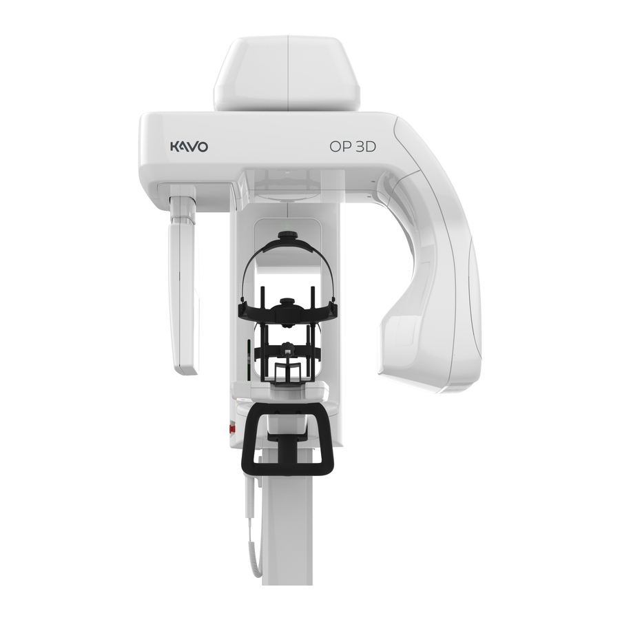
2 Introduction 2 Introduction ™ 2.1 ORTHOPANTOMOGRAPH OP 3D ™ The ORTHOPANTOMOGRAPH OP 3D (later called device) is a dental X-ray device producing high quality digital images of dentition, TM-joints, head and neck area and carpus. To take images, you need a suitable workstation connected to the device and a dental imaging software to capture and manage the images. -
Page 8: Intended Use
2 Introduction 2.2 Intended use ™ ORTHOPANTOMOGRAPH OP 3D is an X-ray device that is intended to be used for imaging of adult and pediatric patients. The device can be configured to take panoramic, cephalometric, or 3D images of the cranio-maxillofacial complex for use in diagnostic support. -
Page 9: Abbreviations
2 Introduction 2.5 Abbreviations Three dimensional Panoramic CEPH Cephalometric Left Right Head Foot Posterior Anterior Posterior-Anterior Field Of View. The cylindrical 3D volume that is reconstructed by the device. Region Of Interest. The anatomical area or region that you are interested to examine. -
Page 10: Disposal And Recycling
2 Introduction 2.7 Disposal and recycling The device and its components are lead-free, including its radiation protection components. The device meets the RoHS Directive 2011/65/EU, WITHOUT any exemptions mentioned in Annex IV. Dispose of the device, accessories and consumables according to local requirements. At least the following parts of the device should be re-cycled according to local and national regulations regarding disposal of non-environmentally friendly materials: •... -
Page 11: Warnings And Precautions For Installation
2 Introduction the device movements and to make sure that the rotating device doesn't collide with the patient during the imaging process. • Always ensure that you can see and hear the patient during the imaging process, while also maintaining visibility to the GUI. •... -
Page 12: Device Modifications
2 Introduction • Additional multiple socket-outlets or extension cords shall not be connected to the system. • The device must be connected to a private, firewall protected LAN network. • Connecting the device to an IT-network that includes other equipment or changing the IT-network can cause unidentified risks to patients or operators. -
Page 13: Overview
3 Overview 3 Overview 3.1 Main parts MAIN DEVICE 1. Column 2. Carriage 3. Upper shelf 4. Rotating unit 5. Sensor (2D/3D)* 6. Sensor (2D)* 7. PAN/3D Tubehead 8. Patient positioning panel 9. Status indicator light 10. Power switch (Back of 11. -
Page 14: Patient Positioning Lights
3 Overview 3.2 Patient positioning lights NOTICE! Appropriate lights are turned on automatically, based on the selected modality, program and FOV. 3.2.1 Positioning light locations A. Tilt light (Panoramic imaging) B. Midsagittal light C. Horizontal light; top of FOV / FH light D. -
Page 15: Cephalometric Lights
3 Overview 3.2.3 Cephalometric lights E. Frankfort-Horizontal (FH) light NOTICE! Lateral programs only. 3.2.4 3D lights B. Midsagittal light C. Horizontal light, top of FOV D. Horizontal light, bottom of FOV NOTICE! The position of the top of FOV light is automatically adjusted according to the selected FOV. -
Page 16: Accessories
3 Overview 3.3 Accessories Chin Rest Bite Block Lip Support (3D, TMJ and edentulous patients) Head Support with Carpus holder a detachable strap (optional) Disposable covers for patient positioning devices: • Disposable covers for Bite Block • Disposable covers for Lip Support •... -
Page 17: Other Detachable Parts
3 Overview 3.4 Other detachable parts CALIBRATION TOOLS: Geometry calibration phantom CEPH calibration rod (CEPH only) 3D QUALITY CONTROL TOOLS: 3D QC phantom 3D QC phantom holder 2D QUALITY CONTROL TOOLS (OPTIONAL): 2D QC test phantom Copper filter - 0.8 mm/1.8 mm PAN QC phantom holder CEPH QC phantom holder ™... -
Page 18: Emergency Stop Switch
3 Overview 3.5 Emergency stop switch An emergency stop switch is located on the left side of the carriage. Pressing the emergency stop switch immediately terminates the imaging and all device movements. NOTICE! An interrupted imaging process cannot be resumed. A new image needs to be taken. -
Page 19: User Interfaces
4 User Interfaces 4 User Interfaces 4.1 Graphical User Interface (GUI) 4.1.1 GUI Overview 1. Selected patient name and Patient Identification (ID). 2. Selection of imaging modality, PAN, CEPH or 3D. 3. Selection of imaging program. 4. Main view area. Shows a dental chart for the selected modality and previews of the taken images. - Page 20 4 User Interfaces IMAGING PROGRAM SETTINGS: Test mode Indicates if Test mode is active. Press Test mode icon to enable/disable device radiation production. Test mode can be used for example to demonstrate the device movements. You can also use the patient positioning panel to enable/disable the Test mode.
-
Page 21: Panoramic View
4 User Interfaces 4.1.2 Panoramic view 4.1.2.1 Panoramic imaging program selection ™ ORTHOselect panoramic dental chart Dental chart shows which segments of the dentition are imaged with the selected imaging program. You can also manually select which segments of the dentition are imaged. - Page 22 4 User Interfaces Panoramic imaging programs Indicates which imaging program is selected. Press the imaging program icons to change the active imaging program; Standard Pediatric Bitewing TMJ, lateral Panoramic Panoramic A sample image for the selected imaging program is shown on the bottom of the GUI.
- Page 23 4 User Interfaces Brightness slider You can adjust the brightness of the shown preview image using the brightness slider. Contrast slider You can adjust the contrast of the shown preview image using the contrast slider. OK button Press OK button to close the image preview. NOTICE! None of the adjustments done to the preview image are saved to the image.
-
Page 24: Cephalometric View
4 User Interfaces 4.1.3 Cephalometric view 4.1.3.1 Cephalometric imaging program selection ™ ORTHOselect cephalometric view The cephalometric view shows which parts of the skull are imaged with the selected imaging program. In lateral imaging, the image field width can be manually adjusted by dragging the slider control. - Page 25 4 User Interfaces Cephalometric imaging programs Indicates which imaging program is selected. Press the imaging program icons to change the active imaging program; Lateral Pediatric lateral Carpus view projection projection projection NOTICE! The carpus view program requires an optional carpus holder. A sample image for the selected imaging program is shown on the bottom of the GUI.
- Page 26 4 User Interfaces 4.1.3.2 QUICKcompose ™ cephalometric image preview NOTICE! Image previews are not shown in full resolution on GUI. Zoom slider You can zoom the preview image in/out using the zoom slider. While zoomed in, you can click and drag to scroll the image. Brightness slider You can adjust the brightness of the shown preview image using the brightness slider.
-
Page 27: View
4 User Interfaces 4.1.4 3D view 4.1.4.1 3D imaging program selection ™ ORTHOselect dental chart Dental chart is used to select the Region of Interest (ROI) for the 3D scan. The FOV changes automatically according to the selections. Press teeth, jaw and TMJ icons to select which parts of the dentition are studied: •... - Page 28 4 User Interfaces FOV size Indicates the currently selected FOV size (H x D). Press the FOV size icon to open a list of the available 3D FOV sizes; 5 x 5, 6 x 9, 9 x 11 and 9 x 14 (optional). Press on the listed FOV size icon to activate it.
- Page 29 4 User Interfaces Scout image program Indicates if the Scout image program is active. A Scout image is taken to verify and perform adjustment to the FOV position and height before initiating a full 3D scan. By default, the Scout image is always active when taking 3D images. Press the Scout image icon to deactivate/activate it.
- Page 30 4 User Interfaces FOV position adjustment You can adjust the position of the FOV, according to the scout image, by sliding the adjustment icons left or right on the scale. The left slider adjusts the FOV position in Posterior (P) - Anterior (A) direction and the right slider in Left (L) - Right (R) direction.
- Page 31 4 User Interfaces 4.1.4.3 QUICKcompose ™ 3D image preview NOTICE! Image previews are not shown in full resolution on GUI. NOTICE! The image has indications from which direction the image is shown; A/ P (Anterior/Posterior), L/R (Left/Right) and H/F (Head/Foot). Preview projection Indicates which preview projection is selected.
- Page 32 4 User Interfaces Contrast slider You can adjust the contrast of the shown preview image using the contrast slider. NOTICE! Adjustment is not saved to the image. OK button Press OK button to close the image preview. ™ ORTHOPANTOMOGRAPH OP 3D Reviewed Suuronen Esa 2019-09-19 12:21 D519207, 19 Approved Lassinen Juuso 2019-10-02 14:37...
-
Page 33: Device Settings
4 User Interfaces 4.1.5 Device settings 1. QUALITY CONTROL Shows a list of Quality Control (QC) programs, their completion status and last completion date. See chapter Quality Control on page 73 for more information on how to take Quality Control images. ™... - Page 34 4 User Interfaces 2. CALIBRATIONS Shows a list of user performable device calibrations, their completion status and last completion date. The calibrations are carried out through this menu. See chapter Calibrations for the user on page 67 for more detailed information on calibration programs and how to perform them.
- Page 35 4 User Interfaces 3. SETTINGS Device settings: Friendly name Set a name for the device, which is shown next to the device settings icon and on the imaging software. 3D Metal Artefact Enable or disable MAR, Metal Artefact Reduction. MAR Reduction is used to reduce the effect of metals and other dense radiopaque objects on the 3D image.
- Page 36 4 User Interfaces Patient size settings: Adjust the default mA and kV values for medium size patient preset. Other patient size selections are changed relatively to the adjustment made. Adjustments made to the 3D imaging program with standard resolution are applied relatively to other resolution selections as well.
- Page 37 4 User Interfaces 4. ABOUT Software Shows the serial numbers of: versions • The main device • Sensors • Tubehead assemblies Shows also the version of the installed firmware. Notices Legal information and terms and conditions for use. Exposure Shows the amount of exposures taken with the device. counters 5.
-
Page 38: Patient Positioning Panel
4 User Interfaces 4.2 Patient positioning panel 1. Carriage up/down slider. The carriage can be driven up and down by sliding a finger on the carriage up/down slider. The speed of the carriage movement depends on the distance the finger is moved. For faster carriage speed, start from the upper/ lower edge of the slider. -
Page 39: Imaging Programs
5 Imaging programs 5 Imaging programs 5.1 Panoramic programs NOTICE! The image field dimensions and segment widths and height differences shown here are for illustrative purposes only. Standard Panoramic imaging program The Standard Panoramic imaging program provides general view of dental and facial anatomy based on panoramic imaging technique. - Page 40 5 Imaging programs Bitewing program A bitewing view of the patient's Premolar-Molar region dentition. You can choose to image both or only other segment in single scan. Press the segments on the dental chart to deselect and select them. TMJ, lateral projection Lateral TMJ program provides a lateral view of the patient's left and right temporomandibular joints.
-
Page 41: Cephalometric Programs
5 Imaging programs 5.2 Cephalometric programs NOTICE! These programs are available only for cephalometric devices. Cephalometric programs provide projection images of patient skull and dental anatomy. Images are utilized in orthodontics and general diagnostics. NOTICE! The image field dimensions shown here are for illustrative purposes only. - Page 42 5 Imaging programs Cephalometric Posterior-Anterior (PA) projection PA projection imaging can be used, for example, to identify any facial asymmetries, dentoalveolar asymmetries, dental crossbite and mandibular displacement. In PA projections, the patient faces away from the tubehead to keep the radiation dose to patient's eyes in minimal level.
-
Page 43: Programs
5 Imaging programs 5.3 3D programs NOTICE! These programs are available only for 3D devices. Always select the smallest feasible FOV size, resolution and imaging parameters for the 3D image in order to follow the ALARA (As Low As Reasonably Achievable) principle. NOTICE! It is always up to the dental professional to select the appropriate FOV, resolution and imaging parameters. -
Page 44: Resolutions
5 Imaging programs FOV 9 x 11 Optimized for imaging the entire dentition, both mandibula and maxilla, maxillary sinuses, jaws with bilateral joints and jaws with airways. Available resolutions: ™ LDT (Low Dose Technology ) resolution Standard resolution High resolution FOV 9 x 14 (optional) Optimized for imaging the entire dentition, both mandibula and maxilla, including airway and upper cervical spine or the sinus, maxillary sinuses,... -
Page 45: Using The Device
6 Using the device 6 Using the device 6.1 General imaging workflow Select imaging Prepare the Power device on program workstation and initialize Place positioning Select patient size to accessories and position set imaging parameters patient to the device 95 kV 8.00 mA Release patient and end study... -
Page 46: Powering On The Device
6 Using the device 6.2 Powering on the device 1. Power the device on. Power switch is located at the rear of the carriage. 2. The device starts initialization. 3. Complete the device initialization by pressing the HOME button on the patient positioning panel when indicator light starts blinking in blue. - Page 47 6 Using the device 6. GUI: Select or ensure the correct settings; imaging modality, imaging program and patient size. If the preset selections are not suitable for the patient, adjust the imaging parameters manually. Imaging Modality CEPH Imaging Program Patient size Imaging parameters NOTICE! Exercise special care when imaging patients outside the typical...
-
Page 48: Patient Positioning
6 Using the device 6.4 Patient positioning 6.4.1 Patient positioning for Panoramic imaging NOTICE! The device can be used to take images of both standing and seated patients. It is recommended to have very tall patients seated for easier positioning. 1. - Page 49 6 Using the device 3. Select the patient positioning accessory according to the image to be taken, attach it to the chin rest and place them on the lower shelf of the device, as shown below. Standard and Pediatric Standard and Pediatric TMJ imaging panoramic and panoramic and...
- Page 50 6 Using the device 7. Tell the patient to remove their glasses, hearing aids, removable dentures, jewellery, hair clips and all other things that can cause artifacts to the image. 8. Protect the patient from radiation according to the local regulations, for example with a lead apron and a thyroid shield.
- Page 51 6 Using the device BITEWING IMAGING: • The patient’s occlusal plane should be horizontal and parallel to the Frankfort- Horizontal light. TMJ IMAGING: • The patient’s Frankfort-Horizontal plane should be close to parallel to the horizontal light. The Frankfort-Horizontal light indicates the center of the field. You can take a TMJ image with the patient's mouth closed or open.
- Page 52 6 Using the device 15. Close the temple supports against the patients head and close the locking lever to lock the head support in place. 16. Ask the patient to close their lips and press their tongue against the palate if possible.
-
Page 53: Patient Positioning For Cephalometric Imaging
6 Using the device 6.4.2 Patient positioning for Cephalometric imaging NOTICE! The device can be used to take images of both standing and seated patients. It is recommended to have very tall patients seated for easier positioning. 1. Press HOME button on the patient positioning panel. The device moves to CEPH HOME (Patient-In) position. - Page 54 6 Using the device 5. Place disposable covers on the ear rods and nasion support. 6. Adjust the device's height to approximately match the patient's height by sliding a finger on the carriage up/down slider. 7. Tell the patient to remove their glasses, hearing aids, removable dentures, jewellery, hair clips and all other things that can cause artifacts to the image.
- Page 55 6 Using the device PA PROJECTION: • The patient's Frankfort-Horizontal plane should be horizontal. NOTICE! The horizontal light is not lit for PA projections. PA REVERSE TOWNE PROJECTION: • Turn the patient's head downwards until the angle between the patient’s Frankfort-Horizontal plane and the horizontal light is around 30°.
- Page 56 6 Using the device 14. Turn the nasion support down and slide it against the patient's nasion when taking Lateral projections. NOTICE! If the patient has wide shoulders that could collide with the rotating unit, ask the patient to cross their arms in front of them in order to contract the soulders.
-
Page 57: Patient Positioning For Carpus Imaging
6 Using the device 6.4.3 Patient positioning for Carpus imaging The Carpus imaging program requires a special carpus holder (optional) to be used. CAUTION! Before taking a Carpus image, make sure the imaging method is approved by local authorities. 1. Press HOME button on the patient positioning panel. The device moves to CEPH HOME (Patient-In) position. - Page 58 6 Using the device 5. Attach the carpus holder by sliding it to the base of the nasion support. 6. Adjust the device's height if needed. 7. Ask the patient to remove any jewellery and all other things that may cause artifacts to the image.
-
Page 59: Patient Positioning For 3D Imaging
6 Using the device 6.4.4 Patient positioning for 3D imaging NOTICE! The device can be used to take images of both standing and seated patients. It is recommended to have very tall patients seated for easier positioning. 1. Press HOME button on the patient positioning panel. The device moves to HOME (Patient-In) position. - Page 60 6 Using the device 4. Place disposable covers on the patient positioning accessories. 5. Adjust the device's height to approximately match the patient's height by sliding a finger on the carriage up/down slider. 6. Open the head support locking lever on the lower shelf, push the head support towards the mirror and lock it leaning forward.
- Page 61 6 Using the device 12. Fine adjust the device's height and adjust patient's head position/orientation using the patient positioning lights as guides. NOTICE! To ensure optimal image quality, pay attention to the correct patient positioning. NOTICE! You can open the mirror and use it to help in positioning the patient.
- Page 62 6 Using the device 16. Lower the head support strap behind patient's head and tighten it to minimize the patient movement. ™ ORTHOPANTOMOGRAPH OP 3D Reviewed Suuronen Esa 2019-09-19 12:21 D519207, 19 Approved Lassinen Juuso 2019-10-02 14:37...
-
Page 63: Taking An Image
6 Using the device 6.5 Taking an image NOTICE! If the patient is feeling insecure or has an exceptional anatomy, use the Test mode to demonstrate the unit movements and to make sure that the rotating unit does not collide with the patient during the imaging process. -
Page 64: Taking Scout And 3D Images
6 Using the device 6.5.2 Taking Scout and 3D images NOTICE! It's recommended to have Scout mode enabled by default. If you do not wish to take a Scout image, deactivate the selection from the GUI. 1. Ensure the correct patient positioning, imaging program selection and that the device is in Ready state with the indicator light turned green. - Page 65 6 Using the device 17. Acknowledge the preview by pressing the OK button. 18. Continue to take the next image, if multiple images need to be taken. 19. Press "End Study" to end the study or return to imaging program. 20.
-
Page 66: Maintenance
7 Maintenance 7 Maintenance The maintenance and calibration procedure intervals described here are minimum requirements and recommendations. The maintenance and calibration procedures can be made more frequent and stringent to comply with local regulations regarding the use and maintenance of dental X-ray devices. 7.1 Cleaning and decontamination NOTICE! Decontamination techniques for the device, its accessories and the room must comply with all laws and regulations within the local jurisdiction. -
Page 67: Calibrations For The User
7 Maintenance 7.2 Calibrations for the user 7.2.1 When to calibrate the device The device must be calibrated and, if necessary, adjusted at regular intervals in accordance with the national regulations regarding the use, maintenance and service of dental X-ray devices. NOTICE! The device has multiple calibration programs, but only the ones listed in this chapter are meant to be performed by the user. - Page 68 7 Maintenance 3. A list of available device calibrations is shown with the status of the calibration. NOTICE! The calibration programs listed on the GUI depend on the device configuration. Calibration status indications: Calibration not performed Recalibration is required. Calibration performed or failed.
-
Page 69: Calibration Procedure
7 Maintenance 7.2.3 Calibration procedure NOTICE! Some calibrations presented in this chapter are not available with all device configurations. Perform the calibrations in the exact order as indicated on the GUI. After you have run all available calibrations successfully, take Quality Control images as instructed in chapter Quality Control on page 73. - Page 70 7 Maintenance 3. Press and hold the exposure button down to take the calibration image. 4. When the exposure warning stops and the program end tone is played, the program is complete. 5. The calibration image appears on the GUI. 6.
- Page 71 7 Maintenance 4. Press and hold the exposure button down to take the calibration image. 5. The calibration results appear on the GUI. NOTICE! This will take several minutes. 6. Acknowledge the calibration by pressing the OK button. 7. Repeat the calibration for the remaining FOV sizes. 7.2.3.4 PAN pixel calibration (2D sensor) This program calibrates the 2D sensor for Panoramic imaging.
- Page 72 7 Maintenance 5. The calibration image appears on the GUI. 6. Acknowledge the calibration result by pressing the OK button. 7.2.3.5 CEPH pixel calibration This program calibrates the sensor for Cephalometric imaging. No calibration tools are required when performing this calibration. NOTICE! This calibration produces X-rays.
-
Page 73: Quality Control
7 Maintenance 7.3 Quality Control The Quality Control (QC) programs in the Quality Control menu are used to ensure that the image quality remains constant. Quality Control should be performed at regular intervals, preferably at least once a month and always after calibration. NOTICE! The device will automatically remind of retaking the QC images. - Page 74 7 Maintenance 5. Protect yourself from radiation. 6. Press and hold the exposure button down to take the QC image. 7. The QC image preview appears on the GUI. 8. Acknowledge the preview by pressing the OK button on the GUI. 9.
- Page 75 7 Maintenance 7.3.2 3D QC NOTICE! This program is available only for devices with 3D modality. 1. GUI: Go to device settings. 2. GUI: Select 3D QC program from the Quality Control menu. 3. Attach the 3D QC phantom holder and the 3D QC phantom to the device. 4.
- Page 76 7 Maintenance 9. Workstation: Visually evaluate and inspect the 3D image for visual defects such as artifacts using the 3D imaging software. NOTICE! The device determines if the QC image is PASSED or FAILED according to measured data, not based on the visible image quality. NOTICE! You should also compare the new QC image to the reference image taken during the installation or the latest service.
-
Page 77: Ceph Qc
7 Maintenance 7.3.3 CEPH QC NOTICE! This program is available only for devices with cephalometric (CEPH) modality. NOTICE! The CEPH QC is an optional, yet recommendable, procedure and is mandatory to be performed where local regulations require it. 1. GUI: Go to device settings. 2. - Page 78 7 Maintenance 7. If required by the local regulations, attach the copper filter in front of the radiation window on the CEPH tubehead. The filter attaches in place with magnets. 8. Protect yourself from radiation. 9. Press and hold the exposure button down to take the QC image. 10.
- Page 79 7 Maintenance NOTICE! You should also compare the new QC image to the reference image taken during the installation or the latest service. Doing this helps you ensure that the image quality has remained constant. NOTICE! The line pair resolution depends also on the other factors than the device itself, for example the imaging Software configurations.
-
Page 80: Annual Maintenance
7 Maintenance 7.4 Annual maintenance An authorized service technician must carry out a full inspection of the device once a year. The following checks must be carried out during the inspection: • Check that the mains cord is not damaged in any way. •... -
Page 81: Troubleshooting
8 Troubleshooting 8 Troubleshooting Problem Possible cause Solution Image is not transferred to Local network connection The device stores the latest the workstation. is disrupted, which causes image until a confirmation loss of data. of a successful transfer to the workstation is received. Re-establish the local network connection and the image data is transferred... -
Page 82: Installation
9 Installation 9 Installation NOTICE! This section of the manual is only for authorized service technicians. NOTICE! Check the package contents against the packing list before installing the device. 9.1 Device package Main device package contents 1. Carriage and rotating unit. 2. -
Page 83: Pre-Installation Requirements
9 Installation 9.2 Pre-installation requirements Familiarize yourself with this manual and the chapter Warnings and requirements page 10 to ensure the safe installation of the device. 9.2.1 Installation location requirements WARNING! Ensure that each of the wall mount fixing screws and the wall can withstand pull-out force of at least 1500 N. -
Page 84: Space Requirements
9 Installation 9.2.2 Space requirements The space requirements for the device to be installed and operated depend on the installation angle of the device. See chapter Device dimensions on page 203 for detailed device dimensions. NOTICE! A full scale installation template is supplied with the device to help selecting the optimal installation position and angle to which the device can be installed in the selected room. -
Page 85: Fixing Hardware And Tools
9 Installation 9.2.3 Fixing hardware and tools The following tools and hardware are required to install and set up the device. These are not included in the delivery, unless otherwise stated. Fixing hardware NOTICE! Fixing hardware for floor and wall fixing are not included in the delivery. The type and length of the fixing hardware to be used to fix the device to the wall and floor depend on the wall and floor materials. -
Page 86: Back Panel Connectors
9 Installation 9.3 Back panel connectors 1. Power cord 2. Ethernet cable for workstation connection 3. Exposure button connector 4. Remote exposure switch connector (optional) 5. External warning light connector (optional) 6. Main fuses F1+F2 (10A fuses installed as default) 7. -
Page 87: Device Installation
9 Installation 9.4 Device installation Follow the instructions in this chapter in the order they are presented. If the device is installed without a cephalometric unit, skip the chapter Cephalometric unit installation on page 103. 9.4.1 Column installation CAUTION! The column will be fixed to the wall using a wall mount supplied with the device. - Page 88 9 Installation 6. Lift and set the column standing to the installation location. NOTICE! Use spirit level to ensure that the wall and floor of the chosen installation location are straight enough to allow the device to be installed vertically straight. 7.
- Page 89 9 Installation 9. CEPH devices only: Determine the installation angle of the device and configure the CEPH wall bracket arm length accordingly. NOTICE! The space requirements for 3 example installation angles are shown in chapter Cephalometric device dimensions on page 206. NOTICE! A full scale installation template is supplied with the device to help selecting the optimal installation position.
- Page 90 9 Installation C. DEVICE INSTALLED PERPENDICULAR TO THE WALL Use the long wall bracket arm supplied separately in the CEPH installation accessories box. Long wall bracket arm enables column rotation between 0-51°. NOTICE! The column can be rotated in range 0-51° with the long arm, but installing the column in angles more than 20°...
- Page 91 9 Installation 12. Push the wall bracket arm to the column side bracket. PAN/3D wall bracket CEPH wall bracket 13. Insert the previoustly detached wall bracket arm pivot screw to the adjustment block. 14. Screw the wall bracket arm pivot screw to the wall bracket arm. Leave the screw slightly loose to allow the adjustment of the wall bracket angle later on.
- Page 92 9 Installation 15. Attach the wall bracket arm to the column side bracket using the same screws, washers (2 pcs) and locking nuts (2 pcs) that were previously detached. Do not tighten the screws fully yet. PAN/3D wall bracket CEPH wall bracket 16.
- Page 93 9 Installation 21. Mark the installation screw locations to the floor using the column floor plate as a template. A. BASIC INSTALLATION Mark all 4 floor screw locations to the floor through the corner holes. Use this installation option only when you are certain on the installation angle of the device and that you don't need to rotate the device during the installation.
- Page 94 9 Installation 23. Lift the column back against the wall. 24. Fix the wall bracket to the wall using appropriate screws and washers. 25. While the column is approximately in the final installation angle, use a spirit level on top of the column to ensure the column is vertically level in both directions. ™...
- Page 95 9 Installation 26. Adjust the tilt of the column if needed. a) Loosen the wall bracket angle locking screws (2 pcs) and adjustment block side screws (2 pcs). b) Adjust the column tilt by screwing both tilt adjustment screws simultaneously. Tilt the column forwards Tilt the column backwards c) Re-tighten the wall bracket angle locking screws (2 pcs) and adjustment block...
-
Page 96: Carriage Installation
9 Installation 9.4.2 Carriage installation 1. Turn the taped edge of the cardboard tray down to allow the carriage to be pulled off the pallet. 2. Pull the carriage to the edge of the pallet so that the diagonal sections of the plywood supports are outside of the pallet. - Page 97 9 Installation 4. Cut the protective plastic aside to reveal the carriage base plate, carriage installation rail and back panel connectors. 5. Check that the device's mains power configuration is applicable to the installation location. NOTICE! The device is delivered with two 10A fuses installed. If installing to other than 230V mains voltage the fuses need to be changed.
- Page 98 9 Installation 7. Loosen the 3 carriage locking bolts on top of the column and ensure that they are facing outwards. 8. Push the carriage installation rail into the slot on the column. The rail locks itself into the slot. 9.
- Page 99 9 Installation 10. Lift the carriage locking bolts (3 pcs) up and tighten them to 25 Nm torque to secure the carriage. CAUTION! The carriage may fall down during use, if the carriage locking bolts are not properly installed and tightened. 11.
- Page 100 9 Installation 12. Support the left hand side plywood cover by hand and detach the 4 indicated screws on the plywood cover and pull it carefully off with the metal supports attached. NOTICE! Support the plywood cover when detaching the last screw to prevent it from falling down.
- Page 101 9 Installation 15. Remove the protective plastic from the carriage carefully so that it doesn't catch and break any circuit boards. 16. Detach the linear movement support screws (5 pcs) from the upper shelf. 17. Lift the linear movement support carefully off. NOTICE! Be careful not to damage the linear movement wiper (white block).
- Page 102 9 Installation 18. Detach the rotating unit support from the carriage (4 screws), push the rotating unit outwards a bit and lift the support off from the rotating unit. NOTICE! You may also move the rotating unit outwards by turning the linear movement screw on the upper shelf by hand.
-
Page 103: Cephalometric Unit Installation
9 Installation 20. Connect the Column control and Emergency switch connector to the connectors in the column. 9.4.3 Cephalometric unit installation This chapter instructs how to install the cephalometric unit to the device. Skip this chapter if the device has not been delivered with cephalometric configuration. 1. - Page 104 9 Installation 2. Take the curved CEPH arm with the head support from the package and hang it to the CEPH arm flange by the large pin. NOTICE! If the device is installed in a tight space and the column has been attached to the floor only with the pivoting screw, you may loosen the wall bracket screws and rotate the device to a more suitable position for the CEPH arm installation.
- Page 105 9 Installation 5. Take the straight CEPH arm with the tubehead from the package by lifting it from the handle attached to the tubehead. 6. Unwrap the film holding the tubehead cable bundle in place. 7. Loosen the 2 screws at the end of the straight CEPH arm to the level of the markings on the arm (approximately 15 mm / 0.6 in).
- Page 106 9 Installation 9. Turn the straight CEPH arm half against the other arm half until it locks in place. NOTICE! Once the arm is in correct position, a latch inside the straight CEPH arm locks the arm in place. 10. Attach the 2 indicated screws (M8x16) to the CEPH arm joint bar to finger tightness. NOTICE! You may need to lift the tubehead a little to align the screw holes properly.
- Page 107 9 Installation 13. Tighten the 2 lower CEPH arm joint bar screws. 14. Tighten the 2 upper CEPH arm joint bar screws. NOTICE! There are holes on the bottom of the CEPH arm that allow you to use a long allen key to tighten the screws. After tightening the screws, cover the holes with the supplied cover plugs.
- Page 108 9 Installation 16. Detach the tubehead handle screw and remove the handle by pulling it off the tubehead. 17. Detach the mirror opto cable and loosen the mirror base plate screws (3 pcs). 18. Lift the mirror base plate off the device. 19.
- Page 109 9 Installation 20. Guide the tubehead cable bundle inside the carriage through the opening and feed them down until the cables come out from the inside of the carriage. 21. Unwrap the tapes holding the cable bundle together. ™ ORTHOPANTOMOGRAPH OP 3D Reviewed Suuronen Esa 2019-09-19 12:21 D519207, 19...
- Page 110 9 Installation 22. Connect the cables inside the carriage. 3-pin connector 14-pin connector Grounding cable NOTICE! The tubehead cable set connectors can be installed only to their correct locations. NOTICE! The CEPH screw kit contains the screw and star washer for the grounding cable.
- Page 111 9 Installation 26. Push the metallic part of the tubehead cable into the previously attached grounding clamp. 27. Connect the pre-routed head support cables to the upper connector on the rear of the device. 28. Attach the cable cover plate with a screw. 29.
-
Page 112: Final Steps Of Device Installation
9 Installation 9.4.4 Final steps of device installation 1. If the column was previously attached to the floor using only the pivoting screw, fix the column to the floor. a) Rotate the device to the correct installation angle. b) Check that the column is still vertically level. If it's not level, adjust the tilt of the column according to the column tilt adjustment instructions in step on page c) Tighten the wall bracket screws. - Page 113 9 Installation 3. Tighten the wall bracket arm pivot screw and attach the screw cap. 4. Install the wall bracket cover plate in place with 2 screws. 5. Connect the mains cord (1), Ethernet cable (2) and exposure switch cable (3) to the rear of the carriage.
- Page 114 9 Installation 6. Attach the exposure switch holder to the column or other metallic surface using its built in magnets or screw it to a non-magnetic surface. Magnetic surface installation Screw installation 1. Pull the rear cover of the holder off. 2.
-
Page 115: Communication Link Configuration
9 Installation 9.5 Communication link configuration 1. Install the Dental Imaging software to the workstation. 2. Connect the device to the local area network (LAN) or directly to the workstation with an Ethernet cable. See the following chapters for more detailed information. NOTICE! The unit requires 1Gb Ethernet connection between the unit and the reconstruction workstation. -
Page 116: Standalone Configuration
9 Installation 9.5.2 Standalone Configuration Standalone Configuration In standalone configuration, the unit is connected directly to a workstation and the unit then reserves the whole network interface card. The unit and the workstation function as a single standalone system with no access to other networks. If it is necessary to be connected to another network or to a server, the workstation will require two network interface cards. -
Page 117: Complete Device Calibration
9 Installation 9.6 Complete device calibration After the installation of the device and during the annual maintenance, a complete calibration procedure must be performed succesfully. Successful calibrations are indicated with green colour and the completion date of the calibration. Calibration status indications: Calibration not Recalibration is required. - Page 118 9 Installation Calibration program order per device configuration: PAN/3D and PAN and PAN/CEPH/3D PAN/CEPH Device movement calibration Z-movement limits X-ray generator calibration 3D pixel calibration Device geometry calibration Collimator calibration PAN pixel calibration (3D sensor) ** 3D geometry calibrations PAN beam alignment calibration PAN geometry calibration ** PAN geometry calibration PAN collimator calibration...
-
Page 119: Accessing The Calibrations
9 Installation 9.6.1 Accessing the calibrations A complete list of calibration programs, required to be performed after the device installation, can be unlocked through the Service mode menu on the GUI. NOTICE! The calibrations programs unlocked through the Service mode menu are intended for service technicians only, and not to be performed by the end user of the unit. - Page 120 9 Installation 6. Installation mode unlocks all calibration programs in the Calibrations menu. 7. Before performing any calibrations, check that the device time setting is correct according to chapter System time check on page 121. ™ ORTHOPANTOMOGRAPH OP 3D Reviewed Suuronen Esa 2019-09-19 12:21 D519207, 19 Approved Lassinen Juuso 2019-10-02 14:37...
-
Page 121: System Time Check
9 Installation 9.6.2 System time check The device receives the system time from the network it is connected to during start-up. This chapter instructs how to check if the received time is correct and how to fix it if it is not. -
Page 122: Device Movement Calibration
9 Installation 9.6.3 Device movement calibration This program is used to calibrate the movements of the upper shelf and the rotating unit. No calibration tools are required when performing this calibration. 1. Select Device movement calibration from the Calibrations menu. 2. -
Page 123: X-Ray Generator Calibration
9 Installation 9.6.5 X-ray generator calibration This program calibrates the PAN/3D tubehead and generator. No calibration tools are required when performing this calibration. NOTICE! This calibration is pre-performed at the factory, but should be performed nonetheless. NOTICE! This calibration produces X-rays. Protect yourself from radiation. 1. -
Page 124: Device Geometry Calibration
9 Installation 6. Acknowledge the calibration result by pressing the OK button. 9.6.7 Device geometry calibration This program calibrates the device imaging geometry for imaging utilizing the 2D/3D sensor. NOTICE! This calibration produces X-rays. Protect yourself from radiation. NOTICE! This calibration is iterative and may need to be run a couple of times before it passes. -
Page 125: Collimator Calibration
9 Installation 9.6.8 Collimator calibration This program calibrates the PAN/3D collimator. No calibration tools are required when performing this calibration. NOTICE! This calibration produces X-rays. Protect yourself from radiation. NOTICE! The X-ray beam size for 3D imaging is verified during this calibration. 1. -
Page 126: Geometry Calibrations
9 Installation 2. Protect yourself from radiation. 3. Press and hold the exposure button down to take the calibration image. 4. When the exposure warning stops and the program end tone is played, the program is complete. 5. The calibration image appears on the GUI. 6. -
Page 127: Pan Beam Alignment Calibration
9 Installation 4. Press and hold the exposure button down to take the calibration image. 5. The calibration results appear on the GUI. NOTICE! This will take several minutes. 6. Acknowledge the calibration by pressing the OK button. 7. Repeat the calibration for the remaining FOV sizes. 9.6.11 PAN beam alignment calibration This program checks that the panoramic beam hits the 2D sensor correctly. -
Page 128: Pan Geometry Calibration
9 Installation 5. The calibration image appears on the GUI. NOTICE! If the calibration program fails and the GUI informs you to adjust the height or tilt of the 2D sensor, adjust the sensor according to chapters 2D Sensor height adjustment on page 184 and 2D Sensor tilt adjustment page 185. -
Page 129: Pan Collimator Calibration
9 Installation 6. The calibration results appear on the GUI. 7. Acknowledge the calibration by pressing the OK button. NOTICE! If the calibration fails and the GUI doesn't tell you to do any adjustments, repeat the calibration. NOTICE! If the calibration fails and the GUI informs you to adjust the sensor, adjust the 2D sensor according to chapter 2D Sensor adjustments on page 182. -
Page 130: Pan Pixel Calibration (2D Sensor)
9 Installation 5. The calibration image appears on the GUI. NOTICE! If the collimator calibration fails and the GUI informs you to adjust the height or tilt of the collimator, adjust the collimator according to chapter PAN/3D Collimator adjustment on page 173. NOTICE! If the collimator calibration fails and the GUI informs that the collimator plates are not parallel, the collimator plate movement may not be working properly. - Page 131 9 Installation 5. The calibration image appears on the GUI. 6. Acknowledge the calibration result by pressing the OK button. ™ ORTHOPANTOMOGRAPH OP 3D Reviewed Suuronen Esa 2019-09-19 12:21 D519207, 19 Approved Lassinen Juuso 2019-10-02 14:37...
-
Page 132: Ceph Head Support Calibration
9 Installation 9.6.15 CEPH head support calibration This program is used to calibrate the different positions of the CEPH head support and nasio support. During this calibration, the alignment of the CEPH arm is also checked and adjusted. No calibration tools are required when performing this calibration. 1. - Page 133 9 Installation 6. Move the nasion support inwards and outwards to it's mechanical limits for a couple of times. 7. Check that the CEPH FH light goes through both of the markers on the 2D sensor cover. This check is done to verify that the CEPH FH light is correctly aligned. NOTICE! If the light doesn't hit both of the marks, adjust the FH light alignment.
-
Page 134: Ceph Generator Calibration
9 Installation 10. Once the CEPH arm is tilted correctly and aligned with the FH light, tighten the 4 CEPH arm fixing bolts. 11. Finish the calibration by pressing the OK button. 12. Attach the PAN/3D tubehead front cover. 9.6.16 CEPH generator calibration This program calibrates the CEPH tubehead and generator. - Page 135 9 Installation 4. When the exposure warning stops and the program end tone is played, the program is complete. 5. The calibration image appears on the GUI. NOTICE! If the calibration fails, the height or tilt of the CEPH primary collimator needs to be adjusted.
-
Page 136: Ceph Secondary Collimator Calibration
9 Installation 9.6.18 CEPH secondary collimator calibration This program is used to verify the position and alignment of the CEPH secondary collimator. No calibration tools are required when performing this calibration. NOTICE! This calibration produces X-rays. Protect yourself from radiation. NOTICE! The X-ray beam size for cephalometric imaging is verified during this calibration. -
Page 137: Ceph Pixel Calibration
9 Installation 3. Press and hold the exposure button down to take the calibration image. 4. When the exposure warning stops and the program end tone is played, the program is complete. 5. The calibration image appears on the GUI. NOTICE! The produced calibration image may contain artifacts (e.g. -
Page 138: Ceph Position Calibration
9 Installation 7. The calibration image appears on the GUI. 8. Acknowledge the calibration result by pressing the OK button. 9.6.21 CEPH position calibration This program is used to calibrate the device movements in cephalometric imaging. This includes the pivot movement of the upper shelf and the linear movement of the rotating unit. - Page 139 9 Installation 4. Pull the nasion support and ear rods to their outmost position and turn them aside. 5. Select CEPH position calibration from the Calibrations menu. 6. Protect yourself from radiation. 7. Press and hold the exposure button down. 8.
-
Page 140: Ceph Mechanical Calibration
9 Installation 9.6.22 CEPH mechanical calibration This program is used to check the correct alignment of the head support and the ear rods. No calibration tools are required when performing this calibration. NOTICE! This calibration produces X-rays. Protect yourself from radiation. 1. -
Page 141: Device Cover Installation
9 Installation 9.7 Device cover installation 9.7.1 Main device covers NOTICE! The screws used to attach the covers are located in the screw kit. 1. Detach the device mirror. 2. Attach upper shelf covers. Place the right cover onto the upper shelf and then push the left cover against it. - Page 142 9 Installation 4. Attach the right carriage side cover. Insert the claws on the cover into the slots on the rear of the column and turn the cover to correct position. Secure the cover in place with one screw under the status indicator light. 5.
- Page 143 9 Installation 8. Re-attach the mirror by guiding the pins on the carriage plate (4pcs) through the keyholes on the mirror plate and sliding the mirror down to lock it in place. 9. Route the mains cord, exposure button cable, Ethernet cable and other optional cables through the cable clamp on the rear of the device.
- Page 144 9 Installation 11. Push the hooks on top of the carriage back plate through the slits on the carriage and press the plate in place. 12. Attach the carriage back plate in place with a screw. 13. Attach the patient handles with 4 screws. Tighten the screws to 10 Nm torque. ™...
- Page 145 9 Installation 14. Attach the tubehead plate in place by pressing it in one side at a time. PAN/3D device CEPH device 15. Install the head support to the lower shelf by screwing the rods in. Slide the head support into the rods. 16.
-
Page 146: Cephalometric Unit Covers
9 Installation 9.7.2 Cephalometric unit covers NOTICE! The screws used to attach the covers are located in the CEPH screw kit. 1. Guide the cables coming from the tubehead to the groove on the CEPH arm and attach the groove strip to the CEPH arm to hide the the cabling. NOTICE! Start to attach the groove strip from the head support side so that the exessive strip hides inside the tubehead covers. - Page 147 9 Installation 6. Press the tubehead rear cover against the front cover and keep it in place with hand. NOTICE! The rear cover doesn't stay in place until the tubehead upper cover is attached. 7. Attach the tubehead upper cover in place with a screw and cover mounting washer. ™...
-
Page 148: Acceptance Tests
9 Installation 9.8 Acceptance tests After the device has been completely calibrated and the device covers attached, perform the device Quality Control programs and store the resulting images for the user as reference. A complete list of Quality control programs, required to be performed after the device installation as part of the acceptance testing can be accessed in Installation mode, unlocked with PIN code 0612 through the Service mode menu. - Page 149 9 Installation 3. Attach the copper filter in front of the radiation window on the PAN/3D tubehead. The filter attaches in place with magnets. 4. Protect yourself from radiation. 5. Press and hold the exposure button down to take the QC image. 6.
- Page 150 9 Installation 10. Save the passed QC image as a reference image for the user and let the user know the reference image location. 11. Detach the PAN QC phantom holder and 2D QC test phantom from the device. 12. Detach the copper filter from the PAN/3D tubehead. 9.8.2 3D QC NOTICE! This program is available only for devices with 3D modality.
- Page 151 9 Installation 7. The QC image appears on the workstation, showing the result of the check. 8. Workstation: Visually evaluate and inspect the 3D image for visual defects such as artifacts using the 3D imaging software. NOTICE! The device determines if the QC image is PASSED or FAILED according to measured data, not based on the visible image quality.
-
Page 152: Ceph Qc (Optional)
9 Installation 9.8.3 CEPH QC (optional) NOTICE! This program is available only for devices with cephalometric (CEPH) modality. NOTICE! The CEPH QC is an optional, yet recommendable, procedure and is mandatory to be performed where local regulations require it. NOTICE! The device's country selection needs to be configured per local requirements before performing the QC programs. - Page 153 9 Installation 6. If required by the local regulations, attach the copper filter in front of the radiation window on the CEPH tubehead. The filter attaches in place with magnets. 7. Protect yourself from radiation. 8. Press and hold the exposure button down to take the QC image. 9.
- Page 154 9 Installation NOTICE! The line pair resolution depends also on the other factors than the device itself, for example the imaging Software configurations. According to the standards, the distinguishable line pair resolution must be 2.5 LP/mm or better. 12. If the image fails on any of the previously listed criteria, redo the QC program. If it fails again, recalibrate the device according to Complete device calibration on page...
-
Page 155: Pan Beam Size Verification (Optional)
9 Installation 9.8.4 PAN beam size verification (optional) This program runs an automatic test to verify, that the X-ray beam hits the active area of the sensor with the required accuracy. No tools are required when performing this test. NOTICE! The PAN beam size verification is an optional, yet recommendable, procedure and is mandatory to be performed where local regulations require it. -
Page 156: Final Inspections
9 Installation 9.9 Final inspections After the device has been installed, perform these checks and tasks, before handing it to the user. 1. Check that the mains cord is not damaged in any way. 2. Check that all covers are attached correctly. 3. - Page 157 9 Installation 4. Check that the leakage current levels are not exceeded if local authorities require it. a) Measure the leakage current according to the following diagrams Permanent installation: Non-permanent installation: b) Check that the measured leakage current values are less than 500uA. 5.
-
Page 158: Additional Installation Procedures
9 Installation 9.10 Additional installation procedures 9.10.1 Device settings The device settings can be changed if required during the installation or service. The user has few device settings that can be accessed through the Settings menu, but the device may be configured more by unlocking more device settings through the Service mode menu. - Page 159 9 Installation DEVICE SETTINGS: Friendly name Set a name for the device, which is shown next to the device settings icon and on the imaging software. 3D Metal Artefact Enable or disable MAR, Metal Artefact Reduction. MAR Reduction is used to reduce the effect of metals and other dense radiopaque objects on the 3D image.
- Page 160 9 Installation CALIBRATION INTERVALS: Change the required calibration and QC interval for the User and for Service (full calibration) according to the local regulations. The device will remind the user when user re-calibration, service re-calibration and new QC retakes are required, according to this setting.
- Page 161 9 Installation INSTALLATION SETTINGS: License If the user has purchased a licensable upgrade for optional imaging programs, for example 9x14 3D FOV, they can be activated through this field. Type the provided license key to the field and press Save to activate the option.
- Page 162 9 Installation DEVICE TIME SETTINGS: Device time Shows the time and date that the device has received from the network. Click Refresh to update the displayed Device time. NOTICE! The time display doesn't update automatically, but needs manual refresh. Fetch new time from Click Start to fetch the time from the network again.
-
Page 163: Mains Power Configuration
9 Installation PATIENT SIZE SETTINGS: Adjust the default mA and kV values for medium size patient preset. Other patient size selections are changed relatively to the adjustment made. Adjustments made to the 3D imaging program with standard resolution are applied relatively to other resolution selections as well. - Page 164 9 Installation The i4100 Back Panel Board contains a switch (SW1), which needs to be configured if the type of installation is changed from permanent to plug connection. NOTICE! If device has been delivered from the factory with plug connection, it has already been configured accordingly.
-
Page 165: Changing The Fuses
9 Installation 9.10.2.2 Mains voltage configuration The device can be used in 220-240 VAC or 100-120 VAC mains voltage. The installed main fuses (F1+F2) need to be configured according to the mains voltage: • 10A suited for 220-240 VAC mains voltage •... -
Page 166: Exposure Tests
9 Installation 9.10.4 Exposure tests The device offers PAN, CEPH and 3D exposure test programs with the device movements disabled. These programs can be used for radiation related measurements, for example, during device installation and acceptance tests. A separate radiation measuring device/equipment is required for taking the radiation measurements. -
Page 167: Remote Exposure Switch Installation
9 Installation 4. Select PAN exposure tests, CEPH exposure tests or 3D exposure tests tab. The PAN exposure test and CEPH exposure test programs allow adjustment of the exposure values kV and mA for the tests. The 3D exposure test program allows selection of different radiaton modes High/ ENDO Resolution (Constant), Standard Resolution (Pulse 10ms) or LDT resolution (Pulse 5ms) and adjusting the related mA. - Page 168 9 Installation 1. Exposure switch 2. Exposure warning light 3. Exposure button connector If a remote exposure switch needs to be used, install it as follows: 1. Connect one end of the remote exposure switch cable to the connector J2 inside the remote exposure switch.
-
Page 169: Additional Wall Bracket Installation
9 Installation 9.10.6 Additional wall bracket installation 1. Detach the cable clamp on the rear of the column. 2. Detach the 3 screws on the holding the wall bracket rail cover in place. TOP OF THE COLUMN BOTTOM OF THE COLUMN 3. -
Page 170: Exhibition Stand Installation
9 Installation 5. Slide the wall bracket up to the insertion points on the column and push the wall bracket into the rail. The rail has openings on both sides at the wall bracket insertion point. 6. Push the rail cover back to the column. 7. -
Page 171: Repacking The Device
9 Installation 2. Attach the device column on the exhibition stand. See the installation instructions supplied with the exhibition stand for more details. 3. If the device is used for other than exhibition use, attach the column to the wall according to instruction in chapter Column installation on page 87... - Page 172 9 Installation 12. Loosen the 3 locking screws holding the carriage on the column and turn them outwards. 13. Carefully push the latch inside the carriage with a flat tool to release the carriage and carefully lower it to the floor. NOTICE! This step requires at least 2 persons.
-
Page 173: Mechanical Adjustments
9 Installation 9.11 Mechanical adjustments Mechanical adjustments should be needed to be performed only during the complete calibration procedure and only if the GUI requests it. If all device calibrations have been completed succesfully, skip this chapter. NOTICE! The following instructions assume that all device covers are attached to the device. - Page 174 9 Installation 3. To move the collimator in UP/DOWN direction, turn the collimator height adjustment screw: a) Clockwise to move the collimator downwards. b) Counter clockwise to move the collimator upwards. NOTICE! The GUI informs you how much the collimator needs to be adjusted and in which direction.
-
Page 175: Ceph Primary Collimator Adjustment
9 Installation 9.11.2 CEPH primary collimator adjustment If the CEPH Tube Sweep Calibration has failed due to the collimator being too high/low or tilted, adjustment is required. NOTICE! This adjustment is required only in special cases. After the adjustment, all cephalometric calibrations related to radiation must be performed again. 1. - Page 176 9 Installation To tilt the collimator in UP/DOWN direction: 1. Loosen the 2 screws on the sides of the collimator assembly. 2. Adjust the tilt by turning the tilt adjustment screw. The amount of tilt can be inspected from the scale at the end of the collimator. •...
- Page 177 9 Installation To rotate the collimator LEFT/RIGHT: 1. Loosen the indicated collimator assembly installation screws (3 pcs). 2. Rotate the collimator assembly by hand. The amount of rotation can be inspected from the scale on the tubehead. 4. After the adjustments, re-tighten the loosened screws and rerun the CEPH Tube Sweep Calibration to verify the adjustment.
-
Page 178: Ceph Secondary Collimator Adjustment
9 Installation 9.11.3 CEPH secondary collimator adjustment If the CEPH Secondary Collimator Calibration has failed due to the collimator being too high/low or tilted, adjustment is required. NOTICE! This adjustment is required only in special cases. After the adjustment, all cephalometric calibrations related to radiation must be performed again. 1. - Page 179 9 Installation b. Adjust the height of the collimator plate by turning the height adjustment screw; • Clockwise to move the collimator downwards. • Counter clockwise to move the collimator upwards. NOTICE! The GUI informs you how much the collimator needs to be adjusted and in which direction.
-
Page 180: 3D Sensor Height Adjustment
9 Installation 3. Re-install the detached covers. NOTICE! When re-installing the PAN/3D tubehead rear cover you must first remove the tubehead plate from the PAN/3D tubehead rear cover. 9.11.4 2D/3D Sensor height adjustment If the device geometry calibration has failed due to the sensor being too high/low the height adjustment is required. - Page 181 9 Installation 4. Remove the screw on the 2D/3D sensor cover. 5. Pull the sensor covers apart to detach them. 6. Loosen the 2 sensor height locking screws. 7. Turn the adjustment screw to adjust the height of the sensor. One turn is equivalent of 0.7 mm.
-
Page 182: Sensor Adjustments
9 Installation 9.11.5 2D Sensor adjustments 9.11.5.1 Removing the 2D sensor covers The cover removal and installation process for 2D sensor varies between device configurations. Follow the instructions applicable to the installed device. 2D ONLY DEVICES 1. Detach the 2D sensor cover screw. 2. - Page 183 9 Installation 2. Detach the collar cover halves by lifting the left side cover upwards and pulling the covers apart. 3. Remove the screw on the 2D sensor cover. 4. Pull the sensor covers apart to detach them. To help unlocking the cover halves, squeeze the left side cover edges while pulling the covers apart.
- Page 184 9 Installation 9.11.5.2 2D Sensor height adjustment NOTICE! This adjustment is required only in special cases and shouldn't be needed to be done during the installation of the device. 1. Detach the 2D sensor covers according to chapter Removing the 2D sensor covers page 182.
- Page 185 9 Installation 9.11.5.3 2D Sensor tilt adjustment 1. Detach the 2D sensor covers according to chapter Removing the 2D sensor covers page 182. 2. Loosen the 2 sensor position locking screws. 3. Turn the upper sensor position adjustment screw to adjust the sensor tilt. You can see the amount of tilt adjusted from the alignment holes.
-
Page 186: Patient Positioning Light Adjustment
9 Installation 2. Loosen the 2 sensor position locking screws. 3. Move the sensor sideways by turning the sensor position adjustment screws (2 pcs). 4. Check that both ends of the sensor have moved evenly from the sensor alignment holes. The holes are equally visible when the sensor is vertical. 5. - Page 187 9 Installation 9.11.6.1 Horizontal and midsagittal lights 1. Detach the carriage back plate, back panel cover, mirror, lower shelf tray and the carriage side covers. See chapter Main device covers on page 141 for more information. 2. The positioning lights are held in place in a fixture with one screw. Loosen the screw to release the light.
- Page 188 9 Installation 9. Re-align the lights if they are still not aligned correctly. 10. Re-install the detached covers. NOTICE! When attaching the left side cover, ensure that the horizontal lasers sit in the middle of the groove so that the cover does not block the positioning light beam 9.11.6.2 Tilt light 1.
- Page 189 9 Installation 7. Re-align the light if it still not aligned correctly. 8. Re-install the detached cover. 9.11.6.3 CEPH FH light 1. Remove the PAN/3D tubehead rear cover by detaching the 3 indicated screws and pull the cover outwards. The screw on the middle of the cover has a screw cover cap over it.
-
Page 190: Ear Rod Adjustment
9 Installation 7. Press the HOME button on the patient positioning panel to drive the device to CEPH HOME position. 8. The cephalometric FH light comes on. Check that the light goes through both of the round alignment markings in the middle of the 2D sensor cover. 9. - Page 191 9 Installation 6. Verify the correct ear rod assembly alignment by performing the CEPH position calibration. 7. Re-install the detached cover. 9.11.7.2 Ear rod height adjustment 1. Move the nasion support and ear rods to their outmost position. 2. Remove the head support mount top cover screws (2 pcs) and detach the cover. 3.
- Page 192 9 Installation 5. Turn the head support to PA position. 6. Pull the left hand side of the upper head support cover over the head support mount. 7. Turn the head support to LAT position and remove the cover. 8. Loosen the ear rod height locking screws (2 pcs) and adjust the eccentric screw to lift/lower the ear holder as required.
- Page 193 9 Installation 11. Re-install the detached covers. NOTICE! Remember to press the lower head support cover back against the upper cover to re-attach it. 9.11.7.3 Ear rod tilt adjustment 1. Move the nasion support and ear rods to their outmost position. 2.
- Page 194 9 Installation 5. Turn the head support to PA position. 6. Pull the left hand side of the upper head support cover over the head support mount. 7. Turn the head support to LAT position and remove the cover. 8. Loosen the ear rod tilt locking screws (2 pcs) and adjust the eccentric screw to adjust the ear holder tilt as required.
-
Page 195: Technical Data
10 Technical data 10 Technical data 10.1 Technical specifications General information Manufacturer: PaloDEx Group Oy Nahkelantie 160, FI–04300 Tuusula, FINLAND Quality system In accordance with ISO13485 standard Environmental management system In accordance with ISO14001 standard Conformity to standards: IEC60601–1 (ed.3)+Am1 IEC60601–1–3: (ed.2)+Am1 IEC60601–1–6 (ed.3.1) IEC60601–1–9 (ed.1) - Page 196 10 Technical data Device data Model: PCX–1 Protection against electric shock Class I Degree of protection Type B applied with no conductive connection to the patient Protection against the ingress of liquids IP20 Cleaning methods • Distilled water • Ethanol 96% •...
- Page 197 10 Technical data Electrical connections Nominal mains voltage 100–120 VAC / 220-240 VAC Tolerance: ± 10% Input power frequency 50 / 60 Hz Nominal current 10A @ 220–240 VAC, 15A @ 100 – 120 VAC Main fuses (F1 & F2) 220–240Vac: Littelfuse 215 (Time–Lag) 10A Cooper Bussman (Time Delay) S505H–10–R...
- Page 198 10 Technical data X–ray generator Generator High frequency DC generator Anode voltage 60 – 95 kV (+/– 5 kV) Anode current 2 – 16 mA (+/– 20%) Exposure time accuracy +/– 5% DAP display accuracy +/– 25% Spine compensation kV / mA compensated Accuracy of radiation output >...
- Page 199 10 Technical data Device physical measures Source–Image 2D/3D sensor 580 mm / 22.83 in distance (SID) 2D sensor PAN imaging 500 mm / 19.7 in CEPH imaging 1745 mm / 68.7 in Dimensions 2D/3D device 1688–2443 x 770 x 1095 mm (H x W x D) 66.5–96.2 x 30.3 x 43.1 in CEPH device...
-
Page 200: Imaging Program Specifications
10 Technical data 10.2 Imaging program specifications NOTICE! The values given in this chapter are nominal values and apply to 220-240 VAC devices. The technical factors and their ranges are limited and may differ from the given values when using a device configured to 100 - 120 VAC. Panoramic programs &... -
Page 201: Patient Size Setting Default Values
10 Technical data 3D imaging programs & technical factors FOV size Resolution Voxel size mA range Exposure time 5 x 5 280 μm 2.0 - 4.0 mA 1.4 - 1.5 s Standard 200 μm 4.0 - 12.5 mA 2.9 - 3.1 s High 125 μm 2.0 - 4.0 mA... -
Page 202: Patient Contacting Parts
10 Technical data 3D programs NOTICE! Tube voltage is fixed to 95 kV Small Medium Large LDT resolution 2.2 mA 2.8 mA 3.6 mA Standard resolution 4.5 mA 8.0 mA 11.0 mA High resolution 2.2 mA 2.8 mA 3.6 mA ENDO resolution 2.2 mA 2.8 mA... -
Page 203: Device Dimensions
10 Technical data 10.4 Device dimensions 10.4.1 Main device dimensions 770 mm / 30.3 in 1095 mm / 43.1 in 340 mm / 13.4 in 163 mm 6.4 in 400 ± 20 mm 15.7 ± 0.8 in 320 ± 20 mm 12.6 ±... - Page 204 10 Technical data PERPENDICULAR INSTALLATION ** 660 mm / 26 in 100 mm / 3.9 in 340 mm 13.4 in * 550 mm / 21.7 in * 1100 mm / 43.3 in ** 1375 mm / 54 in * Minimum operational dimensions ** Recommended minimum dimensions INSTALLATION IN MAX 15°...
- Page 205 10 Technical data INSTALLATION IN 15-40° ANGLE (RIGHT) ** 1105 mm / 43.5 in ** 1290 mm / 51 in NOTICE! This installation setup may require the carriage plywood supports to be removed before lifting the carriage on the column, as they might hit the wall. ** Recommended minimum dimensions ™...
-
Page 206: Cephalometric Device Dimensions
10 Technical data 10.4.2 Cephalometric device dimensions NOTICE! The measures presented in this chapter are given for 3 optimal installation directions. The device can be however installed in various directions. 810 mm / 31.9 in 864 mm / 34 in 770 mm / 30.3 in 1228 -1500 mm / 48.3 - 58.7 in 340 mm / 13.4 in... - Page 207 10 Technical data MAIN DEVICE PERPENDICULAR TO THE WALL • Smallest device footprint widthwise • Requires long CEPH wall bracket * 2000 mm / 78.7 in * 1100 mm / 43.3 in * 900 mm / 35.4 in 290 mm 11.4 in 760 mm / 29.9 in * Minimum operational dimensions...
- Page 208 10 Technical data CEPH ARM PARALLEL TO THE WALL • CEPH tubehead closest to the back wall • Requires short CEPH wall bracket in the longest position * 2100 mm / 82.7 in * 920 mm / 36 in * 1180 mm / 46.5 in 148.5 mm 6 in 51°...
-
Page 209: Wall Bracket Dimensions
10 Technical data 10.4.3 Wall bracket dimensions 450 mm / 18 in 30 mm 17.5 mm / 0.7 in 1.2 in 16 mm / 0.6 in 260 mm / 10.2 in 300 mm / 11.8 in 340 mm / 13.4 in 380 mm / 15.0 in 420 mm / 16.5 in 62 mm... -
Page 210: Exhibition Stand Dimensions
10 Technical data 10.4.4 Exhibition stand dimensions 1090 mm / 42.9 in 20 mm / 0.8 in ™ ORTHOPANTOMOGRAPH OP 3D Reviewed Suuronen Esa 2019-09-19 12:21 D519207, 19 Approved Lassinen Juuso 2019-10-02 14:37... -
Page 211: Symbols That May Appear On The Device Or Its Parts
10 Technical data 10.5 Symbols that may appear on the device or its parts Manufacturer Date of manufacture Serial number Catalog or model number Caution Radiation warning Laser warning Radiation emitting device Type B Applied part Dangerous voltage On or enabled Off or disabled External warning light Exposure switch... - Page 212 10 Technical data Operating instructions Refer to operating instructions for more information. The operating instructions can be supplied electronically or in paper format. Caution: Federal law restricts this device to sale by or on the order of a licensed healthcare practitioner. This symbol indicates that the waste of electrical and electronic equipment must not be disposed as unsorted municipal waste and must be collected separately.
-
Page 213: Electromagnetic Compatibility (Emc) Tables
10 Technical data 10.6 Electromagnetic Compatibility (EMC) tables NOTICE! Medical electrical equipment needs special precautions regarding EMC and needs to be installed according to EMC information. IEC60601-1-2 ed4 testing has verified that electromagnetic interference stimulus has no effect to safety critical functionality of the device. This includes the patient positioning and other imaging pre-conditions, imaging program value selection from the GUI, imaging process, image transfer to the workstation and the image quality. - Page 214 10 Technical data Table 2: Electromagnetic immunity IEC 60601-1-2 Ed4 PCX-1 is suitable for use in the specified electromagnetic environment. The purchaser or user of PCX-1 should assure that it is used in an electromagnetic environment as described below: Immunity Test IEC60601-1-2 Electromagnetic Environment Compliance Level...
- Page 215 10 Technical data Table 3: RF immunity of non-life-support equipment or system IEC 60601-1-2 ed.4 PCX-1 issuitable for use in the specified electromagnetic environment. The purchaser or user of PCX-1 should assure that it is used in an electromagnetic environment as described below: Immunity Test IEC 60601-1-2 Compliance...
- Page 216 10 Technical data Table 4: Separation distances Recommended Separation Distances for Portable and Mobile RF Communications Equipment IEC 60601-1-2 The PCX-1 is intended for use in an electromagnetic environment in which radiated RF disturbances are controlled. The user of PCX-1 can help prevent electromagnetic interference by maintaining a minimum distance between portable and mobile RF communications equipment (transmitters) and the PCX-1 as recommended below, according to the maximum output power of the communications equipment.
-
Page 217: X-Ray Tube Assemblies
10 Technical data INSTALLATION REQUIREMENTS & ENVIRONMENT CONTROL: In order to minimize interference risks, the following requirements shall apply. Cables shielding & grounding All interconnect cables to peripheral devices must meet the requirements given in Technical specifications on page 195. Use of incorrect cables may result in the device causing radio frequency interference. - Page 218 10 Technical data ™ ORTHOPANTOMOGRAPH OP 3D Reviewed Suuronen Esa 2019-09-19 12:21 D519207, 19 Approved Lassinen Juuso 2019-10-02 14:37...
-
Page 219: Workstation Minimum Requirements
No special requirements 3D imaging Only validated GPU’s and WHQL certified driver versions may be used. GPU requirements and driver versions are dependent on the KaVo Driver version installed. Example of supported GPU's: • NVIDIA GTX 1050 Ti with 4GB memory •... - Page 220 10 Technical data Workstation for taking 2D/3D images Operating system • Windows 10 Pro or Enterprise • Windows 8.1 Pro or Enterprise • Windows 7 Professional, Ultimate or Enterprise, with SP1 64-bit version of Windows is required for 3D imaging and recommended for 2D imaging.
- Page 221 216453-2 Headquarters PaloDEx Group Oy | Nahkelantie 160 | P.O. Box 20 FI-04301 Tuusula | FINLAND | Tel. +358 10 270 2000 http://www.kavo.com/en/contact www.kavokerr.com Instrumentarium Dental | 11727 Fruehauf Drive | Charlotte, NC 28273 | U.S.A Tel. 800-558-6120 | Fax. 877-292-6050 Email: KKG.Imaging.CS@kavokerrgroup.com...
Need help?
Do you have a question about the ORTHOPANTOMOGRAPH OP 3D and is the answer not in the manual?
Questions and answers