Table of Contents
Advertisement
Quick Links
Advertisement
Table of Contents

Related Manuals for Strebel S-CB 60


Summary of Contents for Strebel S-CB 60
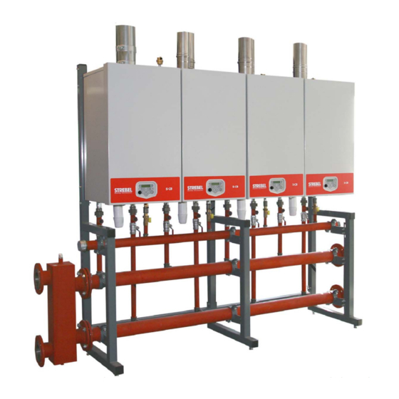
- Page 1 STREBEL S-CB Cascade Kits Models 60 - 80 - 100 - 120 – PX 120 - 150 - Installation & Operating Manual 2x60 up to 12x180 Please read and understand before commencing installation and leave the manual with the customer for future reference.
-
Page 3: Table Of Contents
INDEX INTRODUCTION ............................5 CASCADE SELECTION TABLE ......................6 MAIN DIMENSIONS..........................8 EXPLANATION OF PARTS AND GROUPS ..................10 FRAME GROUPS ........................... 11 MOUNTING THE BOILERS ON THE FRAME ..................13 ... -
Page 5: Introduction
150-180 boilers, but the S-CB PX 120 models can only be combined with the PX 120 model. Strebel Ltd can supply standard cascade systems with mounting frame, piping and low loss headers for up to four boilers in the 60-120 range, four boilers in the PX 120 range and even six in the 150-180 range. For cascades with more boilers, a dedicated system must be designed. -
Page 6: Cascade Selection Table
Cascade Selection Table When selecting a cascade set-up, follow the next steps: 1. First determine the total required power of the set. 2. Determine the best number of boilers required (q. in the table(quantity)). 3. Choose one of the combinations in the table below (even more combinations are available). 4. - Page 7 Continuation from previous page Total 5 Boilers 6 Boilers Model Model Model Model Input 1020 1050 1080...
-
Page 8: Main Dimensions
Main dimensions... -
Page 10: Explanation Of Parts And Groups
Explanation of parts and groups Each cascade set exists of the following parts and groups: The number of S-CB type boilers as selected in chapter 2. The frame group (with locking plates) as determined by the number of boilers. Connecting groups to connect the boilers to the hydraulic groups (one group for each boiler, each group existing of 1 gas, 1 flow and 1 return connecting set). -
Page 11: Frame Groups
Frame groups Figure 4. Cascade frame groups for 1, 2, 3, 4, 5 and 6 boilers. - Page 12 E00.000.158 E00.000.159 E00.000.160 Frame 1 Boiler Frame 2 Boilers Frame 3 Boilers Pos Description part.no. part.no. part.no. standard E02.040.004 E02.040.004 E02.040.004 upper beam E02.040.005 upper beam E02.040.006 upper beam E02.040.007 mid/lower beam E02.040.008 mid/lower beam E02.040.009 mid/lower beam E02.040.010 locking plate E01.004.126 E01.004.126 E01.004.126...
-
Page 13: Mounting The Boilers On The Frame
Mounting the boilers on the frame All lines/piping must be mounted free of tension. The weight of all the components should be supported separately from the boiler so there is no force on the connections. This might influence the mounting position of the boiler. -
Page 14: Mounting The Connecting Sets
Mounting the connecting sets First connect the connecting sets hand-tight to the boiler connections. In a cascade set-up, do NOT use the T-pieces delivered with the boilers. The shortest connecting set should be connected to the gas connection on the boiler. Make sure to connect the flow connecting set (middle length) to the boiler flow connection (left-side connection) and the return connecting set (longest) to the boiler return connection (right-side connection). - Page 15 Connecting sets for boilers S-CB 60 – 120 and S-CB PX 120 NOTICE: Return set for the S-CB PX 120 differs from S-CB Connecting set part.no. boiler boilers boilers boilers Connecting set gas = ¾" E04.000.377 Flow connecting set = 1" E04.000.373 Return connecting set E04.000.374...
-
Page 16: Mounting The Hydraulic Group
Mounting the hydraulic group Connect the gas header to the gas connecting sets. Connect the flow header to the flow connecting sets. Connect the return header to the return connecting sets. Mount all headers with the clamps to the frame. All lines/piping must be mounted free of tension. -
Page 17: Hydraulic Group For 2 Boilers S-Cb 60-120 And/Or S-Cb Px 120
Hydraulic group for 2 boilers S-CB 60–120 and/or S-CB PX 120 Connecting sets in the picture are S-CB versions. 2 Boilers 60–120 Hydraulic group for: E00.000. 152 Description Part number Gas header E02.025.014 Flow header E02.032.006 Return header E02.032.007 Clamp gas header E01.000.205 Clamp flow/return header E01.000.208... -
Page 18: Hydraulic Groups For 3 And 4 Boilers S-Cb + 60-120 And/Or S-Cb Px 120
Hydraulic groups for 3 and 4 boilers S-CB 60–120 and/or S-CB PX 120 Connecting sets in the picture are S-CB versions. 3 Boilers 60–120 4 Boilers 60–120 Hydraulic group for: E00.000.186 E00.000.154 Description Part no. Part no. Gas header E02.032.008 E02.027.018 Flow header E02.039.011... -
Page 19: Hydraulic Groups For 2 And 3 Boilers S-Cb 150-180
Hydraulic groups for 2 and 3 boilers S-CB 150–180 2 Boilers 150–180 3 Boilers 150–180 Hydraulic group for: E00.000.155 E00.000.156 Description Part no. Part no. Gas header E02.027.019 E02.027.017 Flow header E02.039.009 E02.028.056 Return header E02.039.010 E02.028.057 Clamp gas header E01.000.206 E01.000.206 Clamp flow/return header... -
Page 20: Hydraulic Group For 4 Boilers S-Cb 150-180
Hydraulic group for 4 boilers S-CB 150–180 4 Boilers 150–180 Hydraulic group for: E00.000.157 Description Part no. Gas header E02.028.058 Flow header E02.031.005 Return header E02.031.006 Clamp gas header E01.000.207 Clamp flow/return header E01.000.212 Blind flange for gas header E04.010.180 Gasket for flange E07.003.072 Blind flange for flow/return header... -
Page 21: Hydraulic Groups For 5 And 6 Boilers S-Cb + 150-180
Hydraulic groups for 5 and 6 boilers S-CB 150–180 5 Boilers 150-180 6 Boilers 150-180 Hydraulic group for: E00.000.205 E00.000.204 Description Part no Part no Gas header E02.028.091 E02.028.094 Flow header E02.028.092 E02.028.096 Return header E02.028.093 E02.028.095 Clamp gas header E01.000.207 E01.000.207 Clamp flow/return header... -
Page 22: Low Velocity Headers
Low Loss Headers The low loss header can be mounted on the right-hand or the left-hand side of the flow and return headers, whatever is the best place to connect the headers to the heating installation. The opposite end of the flow and return headers must be blocked by the supplied caps or flanges. -
Page 24: Flue Gas And Air Supply
EN 13384-2 “Chimney – Thermal and fluid dynamic calculation methods – Part 2: Chimneys serving more than one heating appliance.” Strebel Ltd Technical can advise on what software can be used for doing these calculations. Do not attempt to design common vent systems without the appropriate software and training. -
Page 25: Installation Examples Flue Gas Systems
10.4 Installation examples flue gas systems. Figure 9. Examples of separate / individual flue systems. Condensate flowing back Condensate flowing back from the flue gas piping from the flue gas piping must always be drained must always be drained before reaching the before reaching the common flue header common flue header... -
Page 26: Installation
Installation Complete the installation with all necessary parts, valves, non-return valves, strainers, air separators and expansion vessel, and connect the low velocity header to the heating installation (see hydraulic examples). Mount the flue gas and air supply lines according to the recommendations of the S-CB / S-CB PX 120 manual and the recommendations in chapter 10. - Page 27 Parameter change is needed. Set parameter C3 (P5DC) to “0”’ (default = “1”). See Chapter 12.3 for setting procedure. IMPORTANT NOTE: The hydraulic piping of the Strebel cascade systems already contains non-return valves underneath each boiler. When other hydraulic systems are used, non-return valves must be fitted in the return pipe of each boiler.
-
Page 28: Parameters
Parameters Before commissioning the cascade installation, a number of parameters has to be changed. These parameters can be programmed on the unit itself, without the use of a computer. Changes in parameter may only be carried out by a skilled commissioning/service engineer, who has had specific training for setting up the S-CB / S-CB PX 120 range boilers. -
Page 29: Control Panel / Display Unit
12.2 Control panel / display unit CONTROL PANEL DISPLAY 2 rows/ each 20 characters ON/OFF MENU RESET ENTER SERVICE COMM. PORT Press and hold for 6 seconds to switch boiler on/off. ON/OFF Is also used as RESET button and ENTER button when RESET ENTER programming. -
Page 30: Setting The Parameters Using The Control Panel
12.3 Setting the parameters using the control panel Programming of the boiler cascade can be done using the control panel. Press the [MENU] button and select the [PARAMETER] menu. See graphics below. Operating screen: H E A T I N G : S T A N D - B Y >... -
Page 31: Monitor Screens
When cascade connection is programmed correctly the boiler display will show the following. Explanation "Cascade communication indicator" NO CASCADE COMMUNICATION > > > no.1 Always showing the fixed ">>>" CORRECT CASCADE COMMUNICATION > no.1 > no.2 > Showing alternating no.1 & no.2 with 1 second interval. 12.4 Monitor screens During normal operation and stand-by, the “◄”... -
Page 32: Cascade Control
Cascade control 13.1 Output control The total cascade set-up will act as one single big boiler, switching on- and off boilers, depending on the total load necessary to adjust and keep the flow temperature at the calculated value. When the heat demand rises, more boilers are switched on, and when heat demand falls, one or more boilers will be switched off. -
Page 33: Options
Options To complete your cascade set-up / heating installation you can choose for next options: Room Temperature Controllers RC Open-Therm with ambient sensor Modulating S04.016.355 RC Open-Therm, allows for a remote ambient sensor to fit. Modulating S04.016.358 RCH E-bus with ambient sensor (for EBC) Modulating S04.016.357 Sensors... - Page 34 - notes -...
- Page 35 - notes -...
- Page 36 Strebel Ltd Unit 10, Invincible Industrial Estate, Invincible Road, Farnborough, Hampshire, GU14 7QU. 01276 685422 01276 685405 info@strebel.co.uk www.strebel.co.uk Further information on our complete product range is available from our website. CAST IRON – CONDENSING – STEEL SHELL – WATER HEATERS – RENEWABLES...
Need help?
Do you have a question about the S-CB 60 and is the answer not in the manual?
Questions and answers