Table of Contents
Advertisement
Quick Links
Download this manual
See also:
Service Manual
Advertisement
Table of Contents

Related Manuals for Keysight Technologies U1461A


Summary of Contents for Keysight Technologies U1461A
- Page 1 Test Equipment Depot - 800.517.8431 - 99 Washington Street Melrose, MA 02176 - TestEquipmentDepot.com Keysight U1461A Insulation Multimeter/ U1453A Insulation Tester User’s Guide...
- Page 2 IMPLIED, WITH REGARD TO THIS agreement and written consent from customarily provided to the public. MANUAL AND ANY INFORMATION Keysight Technologies as governed by Accordingly, Keysight provides the CONTAINED HEREIN, INCLUDING BUT United States and international Software to U.S. government NOT LIMITED TO THE IMPLIED copyright laws.
-
Page 3: Safety Symbols
1000 V protection Category IV 600 V overvoltage CAT IV Earth (ground) terminal 600 V protection Equipment protected throughout by Do not use in distribution systems with double insulation or reinforced voltages higher than 600 V insulation U1461A/U1453A User’s Guide... -
Page 4: Safety Considerations
Keysight U1461A Insulation Multimeter and the U1453A Insulation Tester. Model U1461A appears in all illustrations. The word tester is used to represent both models. – Do not exceed any of the measurement limits defined in the specifications WARNING to avoid instrument damage and the risk of electric shock. - Page 5 – For insulation resistance tests, ensure that you select a suitable test voltage for the equipment to be tested. For model U1461A only: – When measuring current, turn off the circuit power before connecting the tester in the circuit. Remember to place the tester in series with the circuit.
-
Page 6: Measurement Category
Measurement Category The Keysight U1461A/U1453A tester has a safety rating of CAT III, 1000 V and CAT IV, 600 V. Measurement CAT I Measurements performed on circuits not directly connected to the AC mains. Examples are measurements on circuits not derived from the AC mains and specially protected (internal) mains-derived circuits. -
Page 7: Environmental Conditions
–20 °C or –40 °C. You should monitor the ambient temperature sensed by the tester. The tester is operational if the temperature display is not less than –20 °C or –40 °C, according to battery type. The U1461A Insulation Multimeter and U1453A Insulation Tester complies with NOTE the following safety and EMC requirements: –... -
Page 8: Regulatory Markings
The CSA mark is a registered substance elements are expected to trademark of the Canadian Standards leak or deteriorate during normal use. Association. Forty years is the expected useful life of the product. U1461A/U1453A User’s Guide... -
Page 9: Waste Electrical And Electronic Equipment (Weee) Directive 2002/96/Ec
With reference to the equipment types in the WEEE directive Annex 1, this instrument is classified as a “Monitoring and Control Instrument” product. The affixed product label is as shown below. Do not dispose in domestic household waste. U1461A/U1453A User’s Guide... - Page 10 THIS PAGE HAS BEEN INTENTIONALLY LEFT BLANK. U1461A/U1453A User’s Guide...
-
Page 11: Table Of Contents
.........49 U1461A/U1453A User’s Guide... - Page 12 ........94 U1461A/U1453A User’s Guide...
- Page 13 ..........158 Characteristics and Specifications U1461A/U1453A User’s Guide...
- Page 14 THIS PAGE HAS BEEN INTENTIONALLY LEFT BLANK. U1461A/U1453A User’s Guide...
- Page 15 ....92 Figure 2-22 Surface temperature measurement example ..96 Figure 3-1 Detecting AC voltage example ....101 U1461A/U1453A User’s Guide...
- Page 16 THIS PAGE HAS BEEN INTENTIONALLY LEFT BLANK. U1461A/U1453A User’s Guide...
- Page 17 ......31 Table 1-3 U1461A/U1453A rotary switch functions ..32...
- Page 18 THIS PAGE HAS BEEN INTENTIONALLY LEFT BLANK. U1461A/U1453A User’s Guide...
- Page 19 U1461A Insulation Multimeter/U1453A Insulation Tester User’s Guide Introduction About This Manual Preparing Your Tester Your Tester in Brief Cleaning Your Tester Additional Features This chapter helps you set up your tester for the first time. An introduction to all the features of the tester is also given.
-
Page 20: Introduction
Warning denotes a hazard. It calls attention to a procedure which, if not WARNING correctly performed or adhered to, could result in injury or loss of life. Do not proceed beyond a warning note until the indicated conditions are fully understood and met. U1461A/U1453A User’s Guide... -
Page 21: Preparing Your Tester
U1461A/U1453A Quick Start Guide. 3 For any question or problems, refer to the Keysight contact numbers on the back of this manual. - Page 22 1.5 V AA batteries. 6 Ensure that the inner rubber cover is positioned properly. 7 Replace the battery cover back in its original position and tighten the screws. 8 Finally fit the orange rubber holster back on the tester. U1461A/U1453A User’s Guide...
- Page 23 To avoid testers being damaged from battery leakage: CAUTION – Always remove dead batteries immediately. – Always remove the batteries and store them separately if the tester is not going to be used for a long period. U1461A/U1453A User’s Guide...
-
Page 24: Turn On Your Tester
To power ON your tester, turn the rotary switch from the position to any other position. Select the range The tester’s selected range is always displayed on the right-hand end of the bar graph. Selected range Autoranging indicator U1461A/U1453A User’s Guide... -
Page 25: Adjust The Tilt Stand
> is shown on the display instead. Adjust the tilt stand To adjust the tester to a 60° standing position, pull the tilt-stand outward to its maximum reach. IR-USB cable To PC (host) Pull until maximum reach U1461A/U1453A User’s Guide... -
Page 26: Connect To The Handheld Meter Logger Software
Refer to the Keysight Handheld Meter Logger Software Help and Quick Start Guide for more information on the IR communication link and the Keysight Handheld Meter Logger Software. Figure 1-1 Keysight Handheld Meter Logger Software U1461A/U1453A User’s Guide... -
Page 27: Connect The Bluetooth Adapter
– Keysight Mobile Meter (for Android or iOS devices) – Keysight Mobile Logger (for Android or iOS devices) Snap the optic side of the U1117A to the tester’s IR communication port (see Figure 1-2). Bluetooth adapter Figure 1-2 Bluetooth adapter connection U1461A/U1453A User’s Guide... -
Page 28: Your Tester In Brief
Introduction Your Tester in Brief Dimensions Front view 100 mm Figure 1-3 Width dimensions U1461A/U1453A User’s Guide... -
Page 29: Figure 1-4 Height And Depth Dimensions
Introduction Rear and side view 58 mm 218 mm Figure 1-4 Height and depth dimensions U1461A/U1453A User’s Guide... -
Page 30: Overview
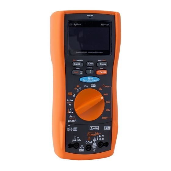
The front panel parts of your tester are described in this section. Table 1-1 Front panel part descriptions Legend Description Learn more on: Vsense detector (model U1461A only)/Red LED indicator page 100 Display screen page 39 Keypad page 35 Rotary switch... -
Page 31: Table 1-2 Rear Panel Parts
Table 1-2 Rear panel parts Legend Description Learn more on: IR communication port page 26 Test lead/probe holders Battery access (under the orange rubber holster) page 21 Tilt stand page 25 Fuse access (under the orange rubber holster) U1461A/U1453A User’s Guide... -
Page 32: Rotary Switch
NOTE insulation resistance tests. See page 35 for more information on the key. U1461A U1453A Table 1-3 U1461A/U1453A rotary switch functions Legend Measurement function U1461A U1453A Learn more on: ✔ ✔ 50 V Insulation resistance test ✔... - Page 33 Introduction Table 1-3 U1461A/U1453A rotary switch functions (continued) Legend Measurement function U1461A U1453A Learn more on: ✔ ✔ 100 V Insulation resistance test ✔ ✔ - Timed test page 67 ✔ ✔ - Dielectric Absorption Ratio test ✔ ✔ - Polarization Index Test ✔...
- Page 34 Introduction Table 1-3 U1461A/U1453A rotary switch functions (continued) Legend Measurement function U1461A U1453A Learn more on: ✔ ✔ AC voltage measurement page 52 AC voltage measurement ✔ page 73 with Low Pass Filter (LPF) ✔ ✔ Auto voltage measurement ✔...
-
Page 35: Keypad
Turning the rotary switch to another position resets the current operation of the key. U1461A U1453A Table 1-4 U1461A/U1453A keypad functions Function when pressed for: Legend Less than 1 second More than 1 second Insulation Resistance (IR) Test: Initiates an IR test (when the rotary switch is in one of the Ω... - Page 36 – Press to scroll through the logged voltage or current measurements. data. – Model U1461A only: Press again to – Press to delete the last logged data. scroll through the frequency (Hz), pulse width (ms), and duty cycle (%) measurements. This –...
- Page 37 Introduction Table 1-4 U1461A/U1453A keypad functions (continued) Function when pressed for: Legend Less than 1 second More than 1 second Log: The recording option (HAND, AUTO, or TRIG) must first be selected in the Setup menu (see Press to switch or cycle between the page 126).
-
Page 38: Table 1-4 U1461A/U1453A Keypad Functions
Null: Press to enable the relative function. – The displayed value is saved as a reference to be subtracted from subsequent Vsense (model U1461A only): Press and hold measurements. to enable the non-contact voltage presence – Press again to view the stored reference indicator. -
Page 39: Display Screen
45 for a tutorial on the analog bar graph located at the bottom of your display screen. General display annunciators The general display annunciators of your tester are described in the Table 1-5. Figure 1-5 Display screen allocation example U1461A/U1453A User’s Guide... -
Page 40: Table 1-5 General Annunciators
– Positive slope for pulse width (ms) and duty cycle (%) measurements – Capacitor is discharging (during capacitance measurement) – Negative slope for pulse width (ms) and duty cycle (%) measurements Short continuity indication Open continuity indication Data logging in progress View mode for reviewing previously logged data U1461A/U1453A User’s Guide... - Page 41 Relative value when Null is enabled Primary measurement display (medium) Primary measurement display (large) Comparison result for Limit mode Reverse diode indication for Auto-diode test Range indication Smooth mode enabled Auto-ranging enabled, Auto-diode enabled, or Auto signal indicator enabled U1461A/U1453A User’s Guide...
- Page 42 Dielectric Absorption Ratio test enabled Polarization Index test enabled Limit comparison enabled Overcurrent indication Trip enabled Ambient temperature indication Elapsed time for Recording mode Timer display for T, DAR, and PI tests Limit value indication for comparison U1461A/U1453A User’s Guide...
- Page 43 Test and Test Lock indication for insulation resistance and earth-bond resistance tests Measuring units for primary display Test voltage for insulation resistance % Scale of 4-20 mA or 0-20 mA Audible continuity test selected Audible disabled Tone enabled Measuring units for secondary display U1461A/U1453A User’s Guide...
- Page 44 A, mA, μA, nA Ampere, units for current measurement nF, μF, mF Farad, units for capacitance measurement Ω, kΩ, MΩ, GΩ, Ohm, units for resistance measurement kHz, Hz Hertz, units for frequency measurement Millisecond, unit for pulse width measurement U1461A/U1453A User’s Guide...
-
Page 45: Figure 1-6 Analog Bar Graph Example
The “+” or “–” sign indicates whether the measured or calculated value is positive or negative. Each bar represents 10 to 100 counts depending on the display count and range selected. Figure 1-6 Analog bar graph example Table 1-7 for the relevant display counts, span, and counts per bar. U1461A/U1453A User’s Guide... -
Page 46: Table 1-7 Analog Bar Graph Display Counts/Bar
Introduction Table 1-7 Analog bar graph display counts/bar Display counts Span 1 Counts/bar Span 2 Counts/bar 6000 0 to 200 >200 1000 0 to 200 >200 2000 0 to 400 >400 U1461A/U1453A User’s Guide... -
Page 47: Input Terminals
440 mA/1000 V, 30 kA fast-acting fuse The remote switch probe is used for insulation resistance Remote switch (IR) and earth-bond probe terminal resistance (EBR) tests. for IR and EBR tests Figure 1-7 Connecting the remote switch probe U1461A/U1453A User’s Guide... -
Page 48: Cleaning Your Tester
2 Turn the tester over, and shake out any dirt that may have accumulated in the terminals. Wipe the case with a damp cloth and mild detergent — do not use abrasives or solvents. Wipe the contacts in each terminal with a clean swab dipped in alcohol. U1461A/U1453A User’s Guide... -
Page 49: Additional Features
OLED brightness from low to medium to high (and back to low again). You are advised to select an suitable brightness level based on your needs to conserve battery life if you wish to control the OLED brightness level manually. U1461A/U1453A User’s Guide... -
Page 50: Hazardous Voltage Indication
Smooth is enabled until the tester is turned off. To permanently enable Smooth, see “Enabling smooth mode” on page 128. Tests the OLED. All OLED pixels are lighted. Use this mode to verify that there are no dead OLED pixels. Press any key to exit this mode. U1461A/U1453A User’s Guide... - Page 51 U1461A Insulation Multimeter/U1453A Insulation Tester User’s Guide Making Measurements Insulation Resistance Test Earth-Bond Resistance Test Measuring AC or DC Voltage Measuring AC or DC Current Measuring Frequency Measuring Resistance Continuity Test Diode Test Measuring Capacitance Measuring Temperature The following sections describe how to take measurements with your tester.
-
Page 52: Making Measurements
Setup), the test is inhibited. The symbol is shown on the display when either the external voltage or the test voltage is greater than 30 V. Disconnect the tester and remove the power of the circuit before proceeding. U1461A/U1453A User’s Guide... -
Page 53: Figure 2-1 Insulation Resistance Test Example
Making Measurements Remote Switch Probe Hold Test will continue until is released. Figure 2-1 Insulation resistance test example U1461A/U1453A User’s Guide... -
Page 54: Using The Remote Switch Probe
Remote Switch Probe. By default the button on the Remote Switch Probe emulates the button on the tester. To change the default button operation, see “Changing the button operation on the remote switch probe” on page 146. U1461A/U1453A User’s Guide... -
Page 55: Locking The Test
By default, the tester will reset the locked status when the test is stopped by pressing . See “Disabling the lock once feature” on page 147 to disable this feature. If you disable this feature, you will need to press to unlock the tester, even if the test has already stopped. U1461A/U1453A User’s Guide... -
Page 56: Timed (T) Insulation Resistance/Earth-Bond Resistance Test
– Because of the time required to perform the T, PI, and DAR tests, the use of NOTE alligator test clips is recommended. – The length of the timer is 1 minute by default. To change this value, see “Changing the insulation resistance and earth-bond resistance test period” page 151 for more information. U1461A/U1453A User’s Guide... -
Page 57: Measuring The Dielectric Absorption Ratio (Dar)
Error is shown on the display if the IR is greater than the maximum range or less than 0.001 MΩ after t1/t15/t30; if the test is interrupted by the user; or if the tester’s battery is low. U1461A/U1453A User’s Guide... -
Page 58: Measuring The Polarization Index (Pi)
Error is shown on the display if the IR is greater than the maximum range or less NOTE than 0.001 MΩ after t1/t15/t30; if the test is interrupted by the user; or if the tester’s battery is low. U1461A/U1453A User’s Guide... -
Page 59: Viewing The Leakage Current
0.001 mA to 1.500 mA from the Setup (see page 153) or by pressing before starting the test. T/DAR/PI tests, Null, Limit, and test lock is disabled when leakage current trip NOTE tests or stepped voltage trip tests are enabled. U1461A/U1453A User’s Guide... -
Page 60: Figure 2-5 Trip Operation
Tripped if measured > After 10 seconds, time up. value set. Press clear the OC warning. If no trip occurs, the last current measured is shown on the primary display. Figure 2-5 TRIP operation U1461A/U1453A User’s Guide... -
Page 61: Performing Stepped Voltage Trip Tests
You can configure the scan signal amplitude end position, number of steps (1 to 100 steps), and dwelling time length (1 to 99 seconds) in the Setup (see page 151 page 152) or by pressing before starting the test. U1461A/U1453A User’s Guide... -
Page 62: Figure 2-6 Scan Signal
The scan dwell time is defined as the length of time the scan signal will “dwell” in the present step before incrementing to the next step. Amplitude (V/ A) Amplitude end position Number of steps Time (t) Scan dwelling time Total dwelling time Figure 2-6 Scan signal U1461A/U1453A User’s Guide... -
Page 63: Figure 2-7 Scan Trip Operation
After 10 seconds, proceed to next step. value set. Press clear the OC warning. If no trip occurs after the last step, the last current measured is shown on the primary display. Figure 2-7 SCAN TRIP operation U1461A/U1453A User’s Guide... -
Page 64: Figure 2-8 Ramp Signal
A lower number of steps will result in a shorter total dwelling time and a more stepped ramp signal. Amplitude Amplitude end position Number of steps Time (t) Total dwelling time Figure 2-8 Ramp signal U1461A/U1453A User’s Guide... -
Page 65: Figure 2-9 Ramp Trip Operation
Next step. Tripped if measured > value set. Press clear the OC warning. If no trip occurs after the last step, the last current measured is shown on the primary display. Figure 2-9 RAMP TRIP operation U1461A/U1453A User’s Guide... -
Page 66: Changing The Insulation Resistance Test Voltage
250 V 10 V to 300 V IR: 500 V 500 V 10 V to 600 V IR: 1000 V 1000 V 10 V to 1100 V [a] Minimum increment of 1 V between each subsequent value. U1461A/U1453A User’s Guide... -
Page 67: Earth-Bond Resistance Test
≤2 Ω is to be measured. When the source voltage is <4.7 V, the tester will inhibit the test automatically. The secondary display indicates the voltage (with auto-ranging enabled). – The APO (auto power-off) function is disabled during the test. – See also “Timed (T) insulation resistance/earth-bond resistance test” page 56. U1461A/U1453A User’s Guide... -
Page 68: Figure 2-10 Earth-Bond Resistance Test Example
Making Measurements Remote Switch Probe Hold > Test will continue until is released. Figure 2-10 Earth-bond resistance test example U1461A/U1453A User’s Guide... - Page 69 2 Press and hold to verify the fuse condition. 3 If the fuse has been blown, FUSE OPEN will be shown on the display. Follow the instructions in the U1461A/U1453A Service Guide to replace the fuse. Fuse blown; replace fuse.
-
Page 70: Measuring Ac Or Dc Voltage
– This tester displays DC voltage values as well as their polarity. Negative DC voltages will return a negative sign on the left of the display. – Press to measure the frequency of the voltage source. See “Measuring Frequency” on page 79 to learn more. U1461A/U1453A User’s Guide... -
Page 71: Figure 2-11 Ac Or Dc Voltage Measurement Example
Making Measurements Figure 2-11 AC or DC voltage measurement example U1461A/U1453A User’s Guide... -
Page 72: Auto Ac Or Dc Signal Identification
While the signal is being identified, you can press to lock the (AC or DC) signal on the primary display. At any time, you can press to stop the Auto function and lock the identified signal component (AC or DC). U1461A/U1453A User’s Guide... -
Page 73: Using The Lpf (Low Pass Filter) Feature For Ac Signals
Making Measurements Using the LPF (Low Pass Filter) feature for AC signals For model U1461A only: Your tester is equipped with an AC low-pass filter to help reduce unwanted electronic noise when measuring AC voltage or AC frequency. Set up your tester to measure AC voltage as shown in Figure 2-11. - Page 74 It is recommended only to use 600 V and 1000 V in the manual range for VSD testing. The low-pass filter can improve measurement performance on composite sine waves that are typically generated by inverters and variable frequency motor drives. U1461A/U1453A User’s Guide...
-
Page 75: Enabling The Lpf In The Setup
AC or DC paths of V, mV, and μA mA measurements. See “Enabling the low-pass filter” on page 156 for more information. Hold > > Hold > > > Figure 2-13 Enabling the low-pass filter U1461A/U1453A User’s Guide... -
Page 76: Measuring Ac Or Dc Current
(in parallel with) any circuit or component when the leads are plugged into the current terminals. Reversing the leads will produce a negative reading, but it will not damage the NOTE Check the tester’s fuses when no current is measured. tester. U1461A/U1453A User’s Guide... -
Page 77: Figure 2-14 Ac Or Dc Current Measurement Example
Placing the probes across (in parallel with) a powered circuit when a lead is CAUTION plugged into a current terminal can damage the circuit you are testing and blow the tester's fuse. This happens because the resistance through the tester's current terminals are very low, resulting in a short circuit. U1461A/U1453A User’s Guide... -
Page 78: Scale Of 4-20 Ma Or 0-20 Ma
You can change the % scale range (4-20 mA or 0-20 mA) in the Setup (page 157). Use the % scale with a pressure transmitter, a valve positioner, or other output actuators to measure pressure, temperature, flow, pH, or other process variables. U1461A/U1453A User’s Guide... -
Page 79: Measuring Frequency
20 Hz. – Pressing controls the input range of the primary function (voltage or NOTE ampere) and not the frequency range. – To obtain the best measuring results for frequency measurements, please use the AC measuring path. U1461A/U1453A User’s Guide... -
Page 80: Figure 2-15 Definition Of Frequency
The bar graph does not indicate frequency but indicates the voltage or ampere value of the input signal. Rise Time Fall Time + Width – Width Period Figure 2-15 Definition of frequency U1461A/U1453A User’s Guide... -
Page 81: Measuring Duty Cycle And Pulse Width
– The duty cycle polarity is displayed to the left of the duty cycle value. indicates a positive pulse width and indicates a negative pulse width. Change the polarity in the Setup (see page 157). U1461A/U1453A User’s Guide... -
Page 82: Measuring Resistance
– The resistance function can produce enough voltage to forward-bias silicon diode or transistor junctions, causing them to conduct. If this is suspected, press to apply a lower current in the next higher range. U1461A/U1453A User’s Guide... -
Page 83: Figure 2-16 Resistance Measurement Example
Making Measurements Figure 2-16 Resistance measurement example U1461A/U1453A User’s Guide... -
Page 84: Continuity Test
1 ms. A brief short causes the tester to emit a short beep. – You can enable or disable the audible alert via the Setup. See “Changing the continuity alert” on page 140 for more information on the audible alert option. U1461A/U1453A User’s Guide... -
Page 85: Figure 2-17 Continuity Test Example
Making Measurements (open) (closed) Figure 2-17 Continuity test example U1461A/U1453A User’s Guide... -
Page 86: Diode Test
– If the beeper is enabled during diode test, the tester will beep briefly for a normal junction and sound continuously for a shorted junction, below 0.04 ± 0.02 V approx. See “Changing the beep frequency” on page 131 to disable the beeper. U1461A/U1453A User’s Guide... -
Page 87: Figure 2-18 Forward-Bias Diode Test Example
Making Measurements Figure 2-18 Forward-bias diode test example U1461A/U1453A User’s Guide... -
Page 88: Figure 2-19 Reverse-Bias Diode Test Example
Making Measurements Reverse the probes (as shown in Figure 2-19) and measure the voltage across the diode again. Figure 2-19 Reverse-bias diode test example U1461A/U1453A User’s Guide... -
Page 89: Using The Auto-Diode Feature
Diode status Primary d isplay Secondary d isplay OL or <0.3 V or >0.8 V –OL or >–0.3 V or <–0.8 V ✘ Within 0.3 V to 0.8 V –OL ✔ Within –0.3 V to –0.8 V ✔ U1461A/U1453A User’s Guide... -
Page 90: Figure 2-20 Auto-Diode Operation
– NG is shown briefly (along with two beeps) if the diode is out of the thresholds. GO: Diode good Press and hold to enable the Auto-diode feature. NG: Diode shorted GO: Diode good GO: Diode good GO: Diode good Figure 2-20 Auto-diode operation U1461A/U1453A User’s Guide... -
Page 91: Measuring Capacitance
– For measuring capacitance values greater than 1000 μF, discharge the capacitor first, then select a suitable range for measurement. This will speed up the measurement time and also ensure that the correct capacitance value is obtained. U1461A/U1453A User’s Guide... -
Page 92: Figure 2-21 Capacitance Measurement Example
Making Measurements – Figure 2-21 Capacitance measurement example U1461A/U1453A User’s Guide... -
Page 93: Viewing The Cable Length Value
The default cable length scale is 1 km per 40 nF (km/C). To change this value, see “Changing the cable length scale” on page 143. You can also change the cable length unit (Meter or Feet). To change this value, “Changing the cable length unit” on page 144. U1461A/U1453A User’s Guide... -
Page 94: Measuring Temperature
The primary display normally shows temperature or the message OL (open thermocouple). The open thermocouple message may be due to a broken (open) probe or because no probe is installed into the input jacks of the tester. U1461A/U1453A User’s Guide... - Page 95 155 for more information. The option to change the temperature unit is locked for certain regions. CAUTION Always set the temperature unit display per the official requirements and in compliance with the National laws of your region. U1461A/U1453A User’s Guide...
-
Page 96: Figure 2-22 Surface Temperature Measurement Example
Making Measurements Type-K Thermocouple Probe Figure 2-22 Surface temperature measurement example U1461A/U1453A User’s Guide... - Page 97 2 Avoid contact between the thermocouple probe and the surface to be measured. 3 After a constant reading is obtained, press to set the reading as the relative reference temperature. 4 Touch the surface to be measured with the thermocouple probe and read the display. U1461A/U1453A User’s Guide...
- Page 98 Making Measurements THIS PAGE HAS BEEN INTENTIONALLY LEFT BLANK. U1461A/U1453A User’s Guide...
-
Page 99: Tester Features
U1461A Insulation Multimeter/U1453A Insulation Tester User’s Guide Tester Features Non-Contact AC Voltage Detection (Vsense) Making Relative Measurements (Null) Capturing Maximum and Minimum Values (Max Min) Freezing the Display (TrigHold and AutoHold) Performing Limit Comparisons (Limit) Recording Measurement Data (Log) Reviewing Previously Recorded Data (View) -
Page 100: Non-Contact Ac Voltage Detection (Vsense)
Tester Features Non-Contact AC Voltage Detection (Vsense) For model U1461A only: Vsense is a non-contact voltage detector that detects the presence of AC voltages nearby. – You are advised to test on a known live circuit within the rated AC voltage... -
Page 101: Figure 3-1 Detecting Ac Voltage Example
AC voltage is recessed within the connector itself. The low sensitivity setting can be used on flush mounted wall sockets or outlets and various power strips or cords. Figure 3-1 Detecting AC voltage example U1461A/U1453A User’s Guide... -
Page 102: Making Relative Measurements (Null)
Press to zero-adjust the display. – For DC voltage measurements, the thermal effect will influence the accuracy of the measurements. Short the test leads and press when the displayed value is stable to zero-adjust the display. U1461A/U1453A User’s Guide... -
Page 103: Capturing Maximum And Minimum Values (Max Min)
MAX, MIN, AVG, or NOW (present) input values. 3 The elapsed time is shown on the display. Press to restart the recording session. 4 Press and hold again to disable Max Min. U1461A/U1453A User’s Guide... - Page 104 The true average value displayed is the arithmetic mean of all readings taken since the start of recording. The average reading is useful for smoothing out unstable inputs, calculating power consumption, or estimating the percentage of time a circuit is active. U1461A/U1453A User’s Guide...
-
Page 105: Freezing The Display (Trighold And Autohold)
To change the default AutoHold threshold count see “Changing the variation count” on page 125 for more information. If the reading value is unable to reach a stable state, the reading value will not NOTE be updated. U1461A/U1453A User’s Guide... -
Page 106: Performing Limit Comparisons (Limit)
>+999.99 Hz <+0 Hz LO to +999.99 kHz +000.00 Hz to HI Pulse width measurement >+000.50 ms <+0 ms LO to +9999.9 ms +000.00 ms to HI Duty cycle measurement >+050.00% <+0% LO to +999.99% +000.00% to HI U1461A/U1453A User’s Guide... - Page 107 – The red LED lights up When the Limit feature is enabled for insulation resistance tests, the red LED NOTE indicator lights up accordingly to the changes in the limit values instead of blinking every 2 seconds. U1461A/U1453A User’s Guide...
-
Page 108: Recording Measurement Data (Log)
Before starting a recording session, set up the tester for the measurements to be recorded. To change the Log option see “Changing the recording option” on page 126 for more information. “Reviewing Previously Recorded Data (View)” on page 113 to review or erase the recorded entries. U1461A/U1453A User’s Guide... -
Page 109: Performing Manual Logs (Hand)
Subsequent readings are automatically recorded into the tester’s memory at the interval specified in the Setup. 2 Press and hold again to exit the interval log mode. U1461A/U1453A User’s Guide... -
Page 110: Performing Event Logs (Trig)
– Insulation resistance tests (page – T/DAR/PI tests (page Event records are triggered by the measured signal satisfying a trigger condition set by the measurement function used in the following modes (shown in Table 3-3 on page 111): U1461A/U1453A User’s Guide... -
Page 111: Table 3-3 Event Log Trigger Conditions
The values of DAR t30 (or DAR t15), DAR t60, PI t1, and PI t10 will be recorded in NOTE every IR rotary switch location. For more information on DAR and PI tests, see page 57 page U1461A/U1453A User’s Guide... - Page 112 The maximum number of readings that can be stored for the event log is 3000 entries. When all entries are occupied, E : FULL will be shown when you press and hold APO (auto power-off) is disabled during the recording session. NOTE U1461A/U1453A User’s Guide...
-
Page 113: Reviewing Previously Recorded Data (View)
(H : Void, A : Void, and E : Void), press and hold to sanitize the log memories. The data sanitization operation may take up to 30 seconds to complete. Do CAUTION not press any keys or turn the rotary switch until the data sanitization operation is completed. U1461A/U1453A User’s Guide... - Page 114 Tester Features THIS PAGE HAS BEEN INTENTIONALLY LEFT BLANK. U1461A/U1453A User’s Guide...
-
Page 115: Setup Options
U1461A Insulation Multimeter/U1453A Insulation Tester User’s Guide Setup Options Using the Setup Menu Setup Menu Summary Setup Menu Items The following sections describe how to change the preset features of your tester. -
Page 116: Using The Setup Menu
– Press to save your changes. – While the menu item’s value is flashing, press to discard your changes. The tester will automatically exit the Setup menu after 30 seconds of inactivity. NOTE U1461A/U1453A User’s Guide... -
Page 117: Editing Numerical Values
1 second to enter the Setup menu. Press Press to edit the move the cursor left selected menu item’s value. or right. Press to increment or decrement the selected digit. Press again to save the changes made. U1461A/U1453A User’s Guide... -
Page 118: Setup Menu Summary
127 per second Default is 5 times per second. Set the settling value from 00001 to 99999. 00001 to 99999 You can also disable this feature (D). SMOOTH page 128 (D or E) Default is disabled (00009-D). U1461A/U1453A User’s Guide... - Page 119 (off). MELODY page 133 or OFF Default is BEEE. Set the power-on greetings to the factory default or disable this feature (off). GREETING FACTORY, USER, or OFF page 134 Default is FACTORY. U1461A/U1453A User’s Guide...
- Page 120 ECHO OFF or ON page 137 Default is disabled (off). Set the tester to print out the measured data when the measuring cycle is completed. PRINT OFF or ON page 137 Default is disabled (off). U1461A/U1453A User’s Guide...
- Page 121 Set the tester to sound a single beep or a tone during continuity alerts for short or open SHORT, OPEN, or TONE circuits. You can also disable this feature (D). CONTINUITY page 140 (E or D) Default is a single beep for short circuits (SHORT-E). U1461A/U1453A User’s Guide...
- Page 122 INHIBIT V 30 V, 50 V or 75 V page 147 Default is 30 V. Set the Dielectric Absorption Ratio in seconds 60:30 or 60:15 (60:30 or 60:15). DAR TIME page 148 (seconds) Default is 60:30 (seconds). U1461A/U1453A User’s Guide...
- Page 123 Set the number of steps for the Ramp function. RAMP STEP 0001 to 1000 page 153 Default is 100 steps. Set the trip current level. TRIP mA 0.001 mA to 1.500 mA page 153 Default is 1.000 mA. U1461A/U1453A User’s Guide...
- Page 124 You can also disable this % & ms +CYCLE-D page 157 feature (D). Default is disabled (+CYCLE-D). MENU LEAD ALERT NONE, USER, or AUTO Set the beep type for the lead alert. [a] Model U1453A and U1461A only. U1461A/U1453A User’s Guide...
-
Page 125: Setup Menu Items
This setting is used with the AutoHold feature (see page 105). When the variation of the measured value exceeds the value of the variation count, the AutoHold feature will be ready to trigger. Parameter Range Defaul t setting AHOLD (5 to 99999) counts 00500 U1461A/U1453A User’s Guide... -
Page 126: Changing The Recording Option
Changing the sample interval duration This setting is used with the Interval Data Logging feature (see page 109). The tester will record a measurement value at the beginning of every sample interval. U1461A/U1453A User’s Guide... -
Page 127: Changing The Data Update Rate
3 Use the arrow keys to change the data update rate. 4 Press to save your changes (or press to discard your changes). 5 Press and hold until the tester restarts to return to normal operation. U1461A/U1453A User’s Guide... -
Page 128: Enabling Smooth Mode
3 Use the arrow keys to change the smooth refresh rate. Select E to enable the Smooth feature. 4 Press to save your changes (or press to discard your changes). 5 Press and hold until the tester restarts to return to normal operation. U1461A/U1453A User’s Guide... -
Page 129: Menu 2
Setup Options Menu 2 Menu Items Learn more on: “Changing the display count” on page 130 U1461A/U1453A User’s Guide... - Page 130 Earth-bond resistance measurements 6600 Insulation resistance measurements 6600 [a] Default range is bolded. [b] Model U1461A only. DAR and PI indications are fixed at 9999 counts. NOTE To change the display count: 1 Press for more than 1 second to enter the Setup menu.
-
Page 131: Menu 3
3840 Hz 3268, 3200 (Hz), or OFF To change the beep frequency: 1 Press for more than 1 second to enter the Setup menu. 2 Browse to Menu 3 > BEEP, and press to edit the value. U1461A/U1453A User’s Guide... - Page 132 Changing the OLED behavior The OLED is set to auto-dim by default. However, you can manually control the OLED brightness by changing the values in this Setup item. Parameter Range Defaul t setting BACKLIT LOW, MEDIUM, HIGH, or AUTO-NN AUTO-90 U1461A/U1453A User’s Guide...
- Page 133 The USER option is reserved for Keysight internal use. NOTE 4 Press to save your changes (or press to discard your changes). 5 Press and hold until the tester restarts to return to normal operation. U1461A/U1453A User’s Guide...
- Page 134 The USER option is reserved for Keysight internal use. NOTE 4 Press to save your changes (or press to discard your changes). 5 Press and hold until the tester restarts to return to normal operation. U1461A/U1453A User’s Guide...
-
Page 135: Menu 4
Defaul t setting BAUD (9600 or 19200) bits/second 9600 To change the baud rate: 1 Press for more than 1 second to enter the Setup menu. 2 Browse to Menu 4 > BAUD, and press to edit the value. U1461A/U1453A User’s Guide... - Page 136 To change the parity check: 1 Press for more than 1 second to enter the Setup menu. 2 Browse to Menu 4 > PARITY, and press to edit the value. 3 Use the arrow keys to change the parity check. U1461A/U1453A User’s Guide...
- Page 137 The tester will automatically send new data to the remote PC host continuously. The tester does not accept any commands from the PC host when this feature is enabled. Parameter Range Defaul t setting PRINT OFF or ON U1461A/U1453A User’s Guide...
- Page 138 3 Use the arrow keys to enable the print feature. 4 Press to save your changes (or press to discard your changes). 5 Press and hold until the tester restarts to return to normal operation. U1461A/U1453A User’s Guide...
-
Page 139: Menu 5
Enabling dual display for voltage and current measurements This setting is used to enable dual display for voltage and current measurements. The AC+DC measurement will be shown on the secondary display. Parameter Range Defaul t setting DUAL DC+AC YES or NO U1461A/U1453A User’s Guide... - Page 140 Changing the continuity alert This setting is used with continuity tests (see page 84). The tester will beep to alert users to the presence of circuit continuities for short or open circuits. U1461A/U1453A User’s Guide...
-
Page 141: Menu 6
Menu 6 Menu Items Learn more on: DEFAULT “Resetting the tester’s Setup options” on page 142 BATTERY “Changing the battery type” on page 142 MIN-Hz “Changing the minimum measurable frequency” on page 143 U1461A/U1453A User’s Guide... - Page 142 Defaul t setting BATTERY PRI or SEC To change the battery type: 1 Press for more than 1 second to enter the Setup menu. 2 Browse to Menu 6 > BATTERY, and press to edit the value. U1461A/U1453A User’s Guide...
- Page 143 This setting is used with capacitance measurements (see page 91). Change the unit (Meter of Feet) of the cable length display. Parameter Range Defaul t setting – (1 to 99) nF CABLE km/C 40 nF-E – D(isabled) or E(nabled) U1461A/U1453A User’s Guide...
- Page 144 3 Use the arrow keys to change the cable length unit. 4 Press to save your changes (or press to discard your changes). 5 Press and hold until the tester restarts to return to normal operation. U1461A/U1453A User’s Guide...
-
Page 145: Menu 7
This setting is used with voltage measurements, up to millivolts (see page 52). Select an appropriate input impedance value according to your requirements. Parameter Range Defaul t setting > mV INPUT 10 MΩ or 1 GΩ 10 MΩ U1461A/U1453A User’s Guide... - Page 146 3 Use the arrow keys to change the function of the remote switch probe button. Select D to disable the remote switch probe button. 4 Press to save your changes (or press to discard your changes). 5 Press and hold until the tester restarts to return to normal operation. U1461A/U1453A User’s Guide...
- Page 147 30 V, 50 V, or 75 V 75 V To change the maximum inhibit voltage: 1 Press for more than 1 second to enter the Setup menu. 2 Browse to Menu 7 > INHIBIT V, and press to edit the value. U1461A/U1453A User’s Guide...
- Page 148 3 Use the arrow keys to change the value of the DAR ratio. 4 Press to save your changes (or press to discard your changes). 5 Press and hold until the tester restarts to return to normal operation. U1461A/U1453A User’s Guide...
-
Page 149: Menu 8
Range Parameter F(actory) U(ser) IR: 50 V 50 V 10 V to 60 V IR: 100 V 100 V 10 V to 120 V IR: 250 V 250 V 10 V to 300 V U1461A/U1453A User’s Guide... -
Page 150: Menu 9
3 Select U and use the arrow keys to change the test voltage. 4 Press to save your changes (or press to discard your changes). 5 Press and hold until the tester restarts to return to normal operation. Menu 9 U1461A/U1453A User’s Guide... - Page 151 This setting is used with insulation resistance tests (see page 67). The scan signal will “dwell” in the present step for the length of time stated in the scan dwelling time before incrementing to the next step. U1461A/U1453A User’s Guide...
- Page 152 3 Use the arrow keys to change the number of steps. 4 Press to save your changes (or press to discard your changes). 5 Press and hold until the tester restarts to return to normal operation. U1461A/U1453A User’s Guide...
- Page 153 To change the trip current value: 1 Press for more than 1 second to enter the Setup menu. 2 Browse to Menu 9 > TRIP mA, and press to edit the value. 3 Use the arrow keys to change the trip current. U1461A/U1453A User’s Guide...
-
Page 154: Menu 10
(or press to discard your changes). 5 Press and hold until the tester restarts to return to normal operation. Menu 10 Menu 10 is for model U1461A only. NOTE Menu Items Learn more on: T-TYPE “Changing the thermocouple type”... - Page 155 °F and °C. – Celsius/Fahrenheit: During temperature measurements, press to switch between °C and °F. – Fahrenheit only: Temperature measured in °F. Press and hold for more than 1 second to unlock this setting. U1461A/U1453A User’s Guide...
- Page 156 3 Use the arrow keys to enable the filter. 4 Press to save your changes (or press to discard your changes). 5 Press and hold until the tester restarts to return to normal operation. U1461A/U1453A User’s Guide...
- Page 157 – D(isable) or E(nable) To enable the duty cycle and pulse width display: 1 Press for more than 1 second to enter the Setup menu. 2 Browse to Menu 10 > % & ms, and press to edit the value. U1461A/U1453A User’s Guide...
-
Page 158: Menu 11
5 Press and hold until the tester restarts to return to normal operation. Menu 11 Menu 11 is only for: NOTE – Model U1461A (EBR and μA mA function only) – Model U1453A (EBR function only) Menu Items Learn more on: LEAD ALERT “Changing the lead alert setting”... - Page 159 This alert will take the form of a beeping sound and caution titled that will flash on the top portion of the primary display. Parameter Range Defaul t setting LEAD ALERT NONE, USER, or AUTO-NN AUTO-03 [a] The “03” value corresponds to a warning duration of 3 seconds U1461A/U1453A User’s Guide...
- Page 160 After a firmware update, if the LEAD ALERT setting is shown as AUTO-00, restore NOTE the setting to the factory default. Refer to “Resetting the tester’s Setup options” on page 142 for more details. U1461A/U1453A User’s Guide...
-
Page 161: Characteristics And Specifications
U1461A Insulation Multimeter/U1453A Insulation Tester User’s Guide Characteristics and Specifications For the characteristics and specifications of the U1461A Insulation Multimeter/ U1453A Insulation Tester, refer to the datasheet at http://literature.cdn.keysight.com/litweb/pdf/5991-4290EN.pdf. - Page 162 Characteristics and Specifications THIS PAGE HAS BEEN INTENTIONALLY LEFT BLANK. U1461A/U1453A User’s Guide...
- Page 163 This information is subject to change without notice. Always refer to the Keysight website for the latest revision. © Keysight Technologies 2014–2016 Edition 9, November 18, 2016 Printed in Malaysia *U1461-90003*...
Need help?
Do you have a question about the U1461A and is the answer not in the manual?
Questions and answers