Table of Contents
Advertisement
Advertisement
Table of Contents

Related Manuals for Keysight Technologies U1231A


Summary of Contents for Keysight Technologies U1231A
- Page 1 Keysight U1231A, U1232A, and U1233A Handheld Digital Multimeter Service Guide...
- Page 2 Limited Rights Do not proceed beyond a WARNING as defined in FAR 27.401 or DFAR notice until the indicated conditions are 227.7103-5 (c), as applicable in any fully understood and met. technical data. Keysight U1231A, U1232A, and U1233A Service Guide...
-
Page 3: Safety Symbols
Warning or Caution information) Equipment protected throughout by AC (Alternating current or voltage) double insulation or reinforced insulation Category III 600 V overvoltage CAT III Earth (ground) terminal protection 600 V Keysight U1231A, U1232A, and U1233A Service Guide... -
Page 4: Safety Considerations
– Always remove dead batteries immediately. – Always remove the batteries and store them separately if the instrument is not going to be used or is being stored for a long period of time. Keysight U1231A, U1232A, and U1233A Service Guide... - Page 5 – Connect the common test lead before you connect the live test lead. When you disconnect the leads, disconnect the live test lead first. – Remove the test leads from the meter before you open the battery cover. Keysight U1231A, U1232A, and U1233A Service Guide...
- Page 6 – Do not operate the meter with the battery cover or portions of the cover WARNING removed or loosened. – To avoid false readings, which may lead to possible electric shock or personal injury, replace the battery as soon as the low battery indicator appears and flashes. Keysight U1231A, U1232A, and U1233A Service Guide...
-
Page 7: Measurement Category
Measurement Category The U1231A, U1232A, and U1233A has a safety rating of CAT III, 600 V. Measurement CAT I Measurements performed on circuits not directly connected to the AC mains. Examples are measurements on circuits not derived from the AC mains and specially protected (internal) mains-derived circuits. -
Page 8: Environmental Conditions
Environmental Conditions This U1231A, U1232A, and U1233A is designed for indoor use and in an area with low condensation. The table below shows the general environmental requirements for this instrument. Environmental cond itions Requirements Operating temperature Full accuracy from –10 °C to 55 °C... -
Page 9: Regulatory Markings
The CSA mark is a registered substance elements are expected to trademark of the Canadian leak or deteriorate during normal use. Standards Association. Forty years is the expected useful life of the product. Keysight U1231A, U1232A, and U1233A Service Guide... -
Page 10: Waste Electrical And Electronic Equipment (Weee) Directive 2002/96/Ec
To contact Keysight for sales and technical support, refer to the support links on the following Keysight websites: – www.keysight.com/find/u1230dmm (product-specific information and support, software and documentation updates) – www.keysight.com/find/assist (worldwide contact information for repair and service) Keysight U1231A, U1232A, and U1233A Service Guide... -
Page 11: Table Of Contents
........35 Keysight U1231A, U1232A, and U1233A Service Guide... - Page 12 ....... . 53 Obtaining Repair Service (Worldwide) ......54 Keysight U1231A, U1232A, and U1233A Service Guide...
- Page 13 Figure 2-2 Replacing the fuse ......50 Keysight U1231A, U1232A, and U1233A Service Guide...
- Page 14 THIS PAGE HAS BEEN INTENTIONALLY LEFT BLANK. Keysight U1231A, U1232A, and U1233A Service Guide...
- Page 15 ......46 Table 2-2 Fuse displayed readings ......47 Keysight U1231A, U1232A, and U1233A Service Guide...
- Page 16 THIS PAGE HAS BEEN INTENTIONALLY LEFT BLANK. Keysight U1231A, U1232A, and U1233A Service Guide...
-
Page 17: Calibration Procedures
Keysight U1231A, U1232A, and U1233A Handheld Digital Multimeter Service Guide Calibration Procedures Keysight Calibration Services Recommended Test Equipment Basic Operating Test Calibration Process Test Considerations Performance Verification Tests Calibration Security Unsecuring the Instrument for Calibration Using the Front Panel for Adjustments... -
Page 18: Keysight Calibration Services
53 for more information on the various calibration services offered. Closed case calibration The U1231A/U1232A/U1233A handheld digital multimeter features closed-case electronic calibration. In other words, no internal electro-mechanical adjustment is required. This instrument calculates correction factors based on the input reference signals you feed into it during the calibration process. -
Page 19: Other Recommendations For Calibration
The tests are only for identifying which functions need adjustment. Please refer to the “Calibration Count” on page 43 and verify that all adjustments have been performed. Keysight U1231A, U1232A, and U1233A Service Guide... -
Page 20: Recommended Test Equipment
<20% of the instrument accuracy specification Diode Fluke 5520A <20% of the instrument accuracy specification Fluke 5520A <20% of the instrument accuracy specification Temperature TM Electronics KMPC1MP — (K-Type thermocouple extension) Short Pomona MDP-S — Keysight U1231A, U1232A, and U1233A Service Guide... -
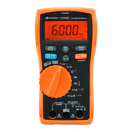
Page 21: Basic Operating Test
(OFF to ON). Check that all the annunciators are displayed in the LCD. Compare the display with the example shown in Figure 1-1. Press any key to exit this mode. Figure 1-1 LCD display screen Keysight U1231A, U1232A, and U1233A Service Guide... -
Page 22: Calibration Process
“Exiting the adjustment mode” on page 42. Ensure that the multimeter has quit the adjustment mode and is turned off. 7 Record the new security code and calibration count in the multimeter's maintenance records. Keysight U1231A, U1232A, and U1233A Service Guide... -
Page 23: Test Considerations
– The instrument should be in the laboratory environment for at least 1 hour prior. – Allow a warm-up period of 3 minutes. – Use shielded twisted-pair PTFE-insulated cables to reduce settling and noise errors. Keep the input cables as short as possible. Keysight U1231A, U1232A, and U1233A Service Guide... -
Page 24: Performance Verification Tests
Use the performance verification tests to verify the measurement performance of the instrument. The performance verification tests use the instrument's specifications listed in the U1231A/U1232A/U1233A User's Guide (available for download at www.keysight.com/find/hhTechLib). The performance verification tests are recommended as acceptance tests when you first receive the instrument. - Page 25 (by shorting the test leads). Apply a 0 Ω calibrator output and allow the multimeter to settle before you press the key. [c] The RH is specified for <60%. Diode 0.020 V 0.020 V 0.020 V Turn the rotary switch to the position. Keysight U1231A, U1232A, and U1233A Service Guide...
- Page 26 [e] AC/DC mV measurement must be enabled prior to this step. Refer to the “Enable the AC/DC mV measurement” section of Chapter 4, “Multimeter Setup Options” in the U1231A/U1232A/U1233A User’s Guide for further information on how to enable the AC/DC mV measurement.
- Page 27 ACμA 60 μA 60 μA, 500 Hz ±0.93 μA ±0.93 μA While the rotary switch is in the 600 μA 600 μA, 500 Hz ±9.3 μA ±9.3 μA position, press the once. Keysight U1231A, U1232A, and U1233A Service Guide...
-
Page 28: Calibration Security
The security code is set to “1234” when the instrument is shipped from the factory. The security code is stored in nonvolatile memory, and does not change when power has been turned off. The security code may contain up to 4 numeric characters. Keysight U1231A, U1232A, and U1233A Service Guide... -
Page 29: Unsecuring The Instrument For Calibration
1 second to enter the calibration security code entry mode. 2 SECU is shown on the display briefly, followed by the calibration security code. Figure 1-2 SECU display Figure 1-3 Calibration security code display Keysight U1231A, U1232A, and U1233A Service Guide... -
Page 30: Calibration Security Code Operation
Press Wrong security code Press entered. Correct security code entered, multimeter enters adjustment mode. Figure 1-4 Calibration security code operation Keysight U1231A, U1232A, and U1233A Service Guide... -
Page 31: To Change The Calibration Security Code
5 If the new calibration security code has been successfully stored, the display will show PASS. Record down your new calibration security code and store it in a safe location. Keysight U1231A, U1232A, and U1233A Service Guide... -
Page 32: To Reset The Calibration Security Code To Its Factory Default
1 second to enter the calibration security code reset mode. SErn is shown on the display briefly, followed by the calibration security code. Figure 1-7 SErn display Figure 1-8 Calibration security code display Keysight U1231A, U1232A, and U1233A Service Guide... - Page 33 1234. If you want to enter a new security code, see “To change the calibration security code” on page 31. Ensure that you record down the new security code. Keysight U1231A, U1232A, and U1233A Service Guide...
-
Page 34: Using The Front Panel For Adjustments
4 Before proceeding with the ambient temperature adjustment, be sure to turn on the multimeter for at least 1 hour with the K-type thermocouple connected. Never turn off the multimeter during an adjustment. This may delete the CAUTION calibration memory for the present function. Keysight U1231A, U1232A, and U1233A Service Guide... -
Page 35: Adjustment Procedure
There is no bar graph display for temperature adjustment. You are highly recommended to complete the adjustments in the same order as NOTE shown in the appropriate table. Keysight U1231A, U1232A, and U1233A Service Guide... - Page 36 10 Turn the rotary switch to the next function according to the Test Function column shown in Table 1-3. Repeat step 3 step 8 for each adjustment point shown in the adjustment table. 11 Verify the adjustments using the “Performance Verification Tests” on page 24. Keysight U1231A, U1232A, and U1233A Service Guide...
-
Page 37: Valid Adjustment Input Values
0.9 to 1.1 × Reference value 60 kΩ 60.00 kΩ 0.9 to 1.1 × Reference value 6 kΩ 6.000 kΩ 0.9 to 1.1 × Reference value 600 Ω 600.0 Ω 0.9 to 1.1 × Reference value Keysight U1231A, U1232A, and U1233A Service Guide... - Page 38 – To perform the adjustment, connect one end of the K-type thermocouple (with miniature TC connector on both ends) to the 5520A TC output, and the other end to the multimeter via a TC-to-banana adapter. Allow at least 1 hour for the multimeter to stabilize. Keysight U1231A, U1232A, and U1233A Service Guide...
- Page 39 0.7 to 1.3 × Reference value 6.000 A (70 Hz) 0.7 to 1.3 × Reference value 3.00 A (70 Hz) 0.7 to 1.3 × Reference value 10 A 10.00 A (70 Hz) 0.7 to 1.3 × Reference value Keysight U1231A, U1232A, and U1233A Service Guide...
-
Page 40: Functional Tests
1 Connect the COM and Ω terminals of the U1252B (or equivalent) to the COM and V terminals of the multimeter under test. 2 Turn the U1231A/U1232A/U1233A rotary switch to the position before proceeding with the following Z functional test. -
Page 41: Vsense Functional Test
5 V, 55 Hz No alert than 1 second. Lo.SE 15 V, 55 Hz Alert on 3 Adjustment or repair is required if the multimeter fails any of the Vsense functional test. Keysight U1231A, U1232A, and U1233A Service Guide... -
Page 42: Exiting The Adjustment Mode
1 Remove all the shorting plugs and connectors from the instrument. 2 Record the new Calibration Count. 3 Press simultaneously to exit the Adjustment Mode. 4 Power off and on again. The instrument will then be secured. Keysight U1231A, U1232A, and U1233A Service Guide... -
Page 43: Calibration Count
2 Take note of the calibration count to keep track of the number of calibrations that have been performed. 3 Press and hold for more than 1 second again to exit the calibration count mode. Keysight U1231A, U1232A, and U1233A Service Guide... -
Page 44: Calibration Error Codes
Calibration error: serial number code invalid Er004 Calibration error: calibration aborted Er005 Calibration error: value out of range Er006 Calibration error: signal measurement out of range Er007 Calibration error: frequency out of range Er008 EEPROM write failure Keysight U1231A, U1232A, and U1233A Service Guide... - Page 45 Keysight U1231A, U1232A, and U1233A Handheld Digital Multimeter Service Guide Service and Maintenance Troubleshooting Checking the Fuse Fuse Replacement Returning the Instrument for Service Replaceable Parts Types of Service Available Obtaining Repair Service (Worldwide) This chapter will help you troubleshoot a failing instrument. It also describes how...
-
Page 46: Service And Maintenance
✔ Verify the baud rate, data bit, stop bit, and parity settings in the multimeter’s Setup mode. (Default values are 9600, 8, 1, and none.) ✔ Verify that the driver for the IR-USB interface is installed. Keysight U1231A, U1232A, and U1233A Service Guide... -
Page 47: Checking The Fuse
Replace the fuse when OL is displayed. Table 2-2 Fuse displayed readings Displayed read ings Current input terminal Part number Fuse rating Fuse heal thy Replace fuse 2110-1402 11 A/1000 V ≈0.0 Ω Keysight U1231A, U1232A, and U1233A Service Guide... -
Page 48: Testing The Fuse
Service and Maintenance Figure 2-1 Testing the fuse Keysight U1231A, U1232A, and U1233A Service Guide... -
Page 49: Fuse Replacement
Replace a new fuse of the same size and rating into the center of the fuse holder. 3 Close the batter cover. Place the battery cover back in its original position and tighten the screws. Keysight U1231A, U1232A, and U1233A Service Guide... -
Page 50: Replacing The Fuse
Service and Maintenance Figure 2-2 Replacing the fuse Keysight U1231A, U1232A, and U1233A Service Guide... -
Page 51: Returning The Instrument For Service
Returning the Instrument for Service Before shipping your instrument for repair or replacement, Keysight recommends that you acquire the shipping instructions from the Keysight Technologies Service Center. A clear understanding of the shipping instructions is necessary to secure your product for shipment. -
Page 52: Replaceable Parts
1 Contact your nearest Keysight Sales Office or Service Center. 2 Identify the parts by the Keysight part number shown in the support parts list. 3 Provide the instrument model number and serial number. Keysight U1231A, U1232A, and U1233A Service Guide... -
Page 53: Types Of Service Available
Service and Maintenance Types of Service Available If your instrument fails during the warranty period, Keysight Technologies will repair or replace it under the terms of your warranty. Extended service contracts Many Keysight products are available with optional service contracts that extend the covered period after the standard warranty expires. -
Page 54: Obtaining Repair Service (Worldwide)
Service and Maintenance Obtaining Repair Service (Worldwide) To obtain service for your instrument (in-warranty or under service contract), contact your nearest Keysight Technologies Service Center. They will arrange to have your unit repaired or replaced, and can provide warranty information where applicable. - Page 55 This information is subject to change without notice. Always refer to the Keysight website for the latest revision. © Keysight Technologies 2011 – 2017 Edition 10, June 30, 2017 Printed in Malaysia *U1231-90035* U1231-90035 www.keysight.com...
Need help?
Do you have a question about the U1231A and is the answer not in the manual?
Questions and answers