Table of Contents
Advertisement
USER MANUAL
PXI-6683 Series
Timing and Synchronization Module
This manual describes the electrical and mechanical aspects of the PXI-6683 and PXI-6683H,
and contains information concerning their operation and programming.
Conventions
Caution
avoid injury, data loss, or a system crash. When this symbol is marked on the
product, refer to the
take.
National Instruments Documentation
The PXI-6683 Series User Manual is one piece of the documentation set for your
measurement system. You could have any of several other documents describing your
hardware and software. Use the documentation you have as follows:
•
Measurement hardware documentation—This documentation contains detailed
information about the measurement hardware that plugs into or is connected to the
computer. Use this documentation for hardware installation and configuration
instructions, specifications about the measurement hardware, and application hints.
•
Software documentation—Refer to the NI-Sync Help, available at
You can download NI documentation from
Related Documentation
The following documents contain information that you might find helpful as you read this
manual.
•
PICMG 2.0 R3.0, CompactPCI Core Specification, available from PICMG at
www.picmg.org
•
PXI Specification, Revision 2.1, available from
•
NI-VISA User Manual, available from
•
NI-VISA Help, included with the NI-VISA software.
•
NI-Sync User Manual, available from
This icon denotes a caution, which advises you of precautions to take to
Safety Information
.
section of the
ni.com/manuals
www.pxisa.org
ni.com/manuals
ni.com/manuals
Introduction
for precautions to
ni.com/manuals
.
.
.
.
.
Advertisement
Table of Contents

Related Manuals for National Instruments PXI-6683 Series


Summary of Contents for National Instruments PXI-6683 Series
- Page 1 National Instruments Documentation The PXI-6683 Series User Manual is one piece of the documentation set for your measurement system. You could have any of several other documents describing your hardware and software. Use the documentation you have as follows: •...
-
Page 2: Table Of Contents
PXI Express system; some PXI timing slot features are not available using a PXI-6683H board. What You Need to Get Started To set up and use a PXI-6683 Series timing and synchronization module, you need the following items: •... -
Page 3: Unpacking
Do not operate the product in a manner not specified in this document. Misuse of the product can result in a hazard. You can compromise the safety protection built into the product if the product is damaged in any way. If the product is damaged, return it to National Instruments for repair. - Page 4 Operate the product only at or below Pollution Degree 2. Pollution is foreign matter in a solid, liquid, or gaseous state that can reduce dielectric strength or surface resistivity. The following is a description of pollution degrees: • Pollution Degree 1 means no pollution or only dry, nonconductive pollution occurs. The pollution has no influence.
-
Page 5: Installing And Configuring
Examples include electricity meters and measurements on primary overcurrent protection devices and on ripple control units. Installing and Configuring This section describes how to install the PXI-6683 Series hardware and software and how to configure the device. Installing the Software... -
Page 6: Configuring The Module
Remove any packing material from the front panel screws and backplane connectors. Insert the PXI-6683 Series module into the PXI or PXI Express hybrid slot. Use the injector/ejector handle to fully insert the module into the chassis. Screw the front panel of the module to the front panel mounting rail of the chassis. -
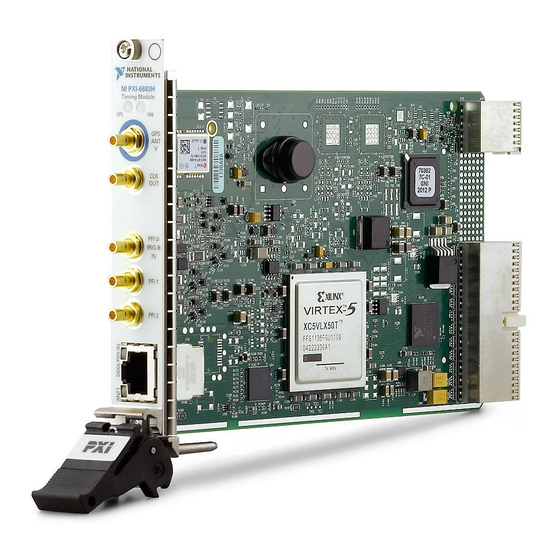
Page 7: Hardware Overview
Hardware Overview This chapter presents an overview of the hardware functions of the PXI-6683 Series, shown in Figure 1. on page 7. Figure 1. Isometric View of the PXI-6683 Series PXI-6683 PXI-6683H Figure 2. on page 8 provides a functional overview of the PXI-6683 Series:... - Page 8 Figure 2. Functional Overview of the PXI-6683 Not in NI PXI-6683H AC Coupled PXI_CLK10_IN CLKIN Clock Detector TCXO (Oscillator) CLKOUT AC Coupling PXI_CLK10 GPS RF IN +5 V DC OUT Receiver Not in NI PXI-6683H PFI 0 IRIG-B AM Receiver PXI_STAR<0..12>...
-
Page 9: Pxi-6683 Front Panel And Leds
GPS Antenna Connector CLKOUT Connector CLKIN Connector PFI0/IRIG-B Input Connector PFI<1..2> Connectors Ethernet Speed LED Ethernet ACT/LINK LED 10. RJ-45 Ethernet Connector The GPS LED indicates the status of the GPS hardware. PXI-6683(H) User Manual | © National Instruments | 9... - Page 10 Uncalibrated or Slave Blinking Green (2 seconds) Master or Premaster Faulty *1588 and/or 802.1AS has been disabled or stopped. The Ethernet Speed LED indicates the PXI-6683 Series Ethernet link speed. Table 4. Ethernet Speed LED Description Color Status 10 Mbps...
-
Page 11: Connectors
Ethernet link established Blink Ethernet activity occurring Connectors This section describes the connectors on the front panel of the PXI-6683 Series. Refer to Figure 3. on page 9 for the location of the connectors. • GPS ANT—GPS antenna RF input and DC power output for the active GPS antenna. - Page 12 PXI_CLK10 This signal is the PXI 10 MHz backplane clock. By default, this signal is the output of the native 10 MHz oscillator in the chassis. A PXI-6683 Series in the system timing slot can replace this signal with PXI_CLK10_IN.
-
Page 13: Clock And Event Generation
Clock and Event Generation The PXI-6683 Series can generate two types of clock signals. The first type is generated with a precise 10 MHz oscillator, and the second is generated with the synchronized timebase. The following sections describe the two types of clock generation and explain the considerations for choosing either type. -
Page 14: Routing Signals
Routing Signals The PXI-6683 Series has versatile trigger routing capabilities. It can route signals to and from the front panel, the PXI star triggers, and the PXI triggers. In addition, the polarity of the destination signal can be inverted, which is useful when handling active-low digital signals. - Page 15 Table 7. on page 16 summarizes the sources and destinations of the PXI-6683 Series. The destinations are listed in the horizontal heading row, and the sources are listed in the column at the far left. A check in a cell indicates that the source and destination combination defined by that cell is a valid routing combination.
-
Page 16: I/O Considerations
PFI lines for output. Caution Do not attempt to drive signals into PFI terminals set up as outputs. Doing so can damage the PXI-6683 Series or the device driving the PFI terminal. 16 | ni.com | PXI-6683(H) User Manual... - Page 17 When setting up PFI0 as an output (future time events or clocks), ensure that PFI0 is driven low for at least 5 ms after the line is set up. Alternately, ensure that the external receiver can tolerate a slow rising edge. PXI-6683(H) User Manual | © National Instruments | 17...
- Page 18 • Before disabling PFI0 set up as an output, drive the output low to avoid a very slow ramp down. • Any time a route is set up or changed where PFI0 is the source or the destination, allow for a 5 ms settling time. For more information, refer to KnowledgeBase 4E9BT88P at ni.com/support Brief Overview of PXI Synchronization Features...
- Page 19 National Instruments does not recommend the use of PXI_Trigger lines for clock distribution. The preferred method for clock distribution is the use of the PXI_STAR triggers. However, the PXI-6683 Series does support routing of clocks to the PXI_Trigger lines, in case you must use them.
- Page 20 Refer to the Choosing the Type of Routing section for more information about the synchronization clock. Choosing the Type of Routing The PXI-6683 Series routes signals in one of two ways: asynchronously or synchronously. The following sections describe the two routing types and the considerations for choosing each type.
- Page 21 Propagation delay of the signal through the PXI-6683 Series. • Time for the receiver to recognize the signal. The source of an asynchronous routing operation on the PXI-6683 Series can be any of the following lines: • Any front panel PFI pin (PFI<0..2>) •...
- Page 22 CtoQ Trigger Output The PXI-6683 Series supports synchronous routing to either the rising or falling edge of the synchronization clock. In addition, the polarity of the destination signal can be inverted, which is useful when handling active-low digital signals. Synchronous routing can be useful for eliminating skew when sending triggers to several destinations.
-
Page 23: Synchronization
Any PXI trigger line (PXI_TRIG<0..7>) In the PXI-6683 Series, the synchronization clock for synchronous routes is always PXI_CLK10. The destination of a synchronous routing operation on the PXI-6683 Series can be any of the following lines: • Any front panel PFI pin (PFI<0..2>) •... -
Page 24: Gps
IRIG-B 12X (AM) and IRIG-B 00X (DC), compliant with the IRIG 200-04 standard. When configured to synchronize to an IRIG-B AM source, the PXI-6683 Series will be able to accept a 1 kHz AM modulated IRIG-B 12X signal on its PFI0 input. When configured to synchronize to an IRIG-B DC source, the PXI-6683 Series will be able to accept an IRIG-B 00X DC encoded signal on its PFI0 input. -
Page 25: 802.1As
Series to synchronize to IEEE 1588, in which case, the standard defines how the master will be selected. If the PXI-6683 Series is selected as the IEEE 1588 master, and it is not configured to synchronize to GPS or IRIG-B, it will use its internal free-running timebase, which will be updated to the host computer's system time during power up. -
Page 26: Synchronization Best Practices
Timing System Performance The PXI-6683 Series can generate or receive a 1 Hz pulse per second signal on any PFI or PXI trigger terminal. You can set up this signal to transition on the seconds boundary of the synchronized system time. You can then use this signal to analyze system performance by connecting two or more pulse per second signals to an oscilloscope and measuring the latency between them. - Page 27 Windows configuration panels. GPS Synchronization Best Practices The PXI-6683 Series module has one SMB female connector on its front panel for a GPS active antenna. The connector provides a DC voltage to power the antenna and alos serves as input for the GPS RF signal.
-
Page 28: Calibration
The calibration constant is used at start-up when the board is configured for free running mode. When the PXI-6683 Series module is configured to use GPS, IEEE 1588, IEEE 802.1AS, IRIG-B, or PPS as its time reference, the TCXO frequency is adjusted according to the time reference, and the calibration constant is no longer used. - Page 29 For patents covering NI products/technology, refer to the appropriate location: Help»Patents in your software, the file on your media, or the National Instruments Patent Notice patents.txt . You can find information about end-user license agreements (EULAs) and third-party legal notices ni.com/patents...
Need help?
Do you have a question about the PXI-6683 Series and is the answer not in the manual?
Questions and answers