Table of Contents
Advertisement
USER GUIDE
NI sbRIO-961x/963x/964x and
NI sbRIO-9612XT/9632XT/9642XT
Single-Board RIO OEM Devices
Caution
The NI sbRIO-961x/9612XT/963x/9632XT/964x/9642XT must be installed
inside a suitable enclosure prior to use. Hazardous voltages may be present.
Caution
National Instruments makes no product safety, electromagnetic compatibility
(EMC), or CE marking compliance claims for NI sbRIO devices. The end-product supplier
is responsible for conformity to any and all compliance requirements.
Exercise caution when placing the NI sbRIO devices inside an enclosure.
Caution
Auxiliary cooling may be necessary to keep the device under the maximum ambient
temperature rating for the NI sbRIO device. Refer to
information about the maximum ambient temperature rating.
This document provides dimensions, pinouts, connectivity information,
and specifications for the National Instruments sbRIO-9611, sbRIO-9612,
sbRIO-9612XT, sbRIO-9631, sbRIO-9632, sbRIO-9632XT, sbRIO-9641,
sbRIO-9642, and sbRIO-9642XT. The devices are referred to inclusively in
this document as the NI sbRIO-961x/9612XT/963x/9632XT/964x/
9642XT.
Specifications
section for more
Advertisement
Table of Contents

Related Manuals for National Instruments sbRIO-9611


Summary of Contents for National Instruments sbRIO-9611
- Page 1 NI sbRIO-9612XT/9632XT/9642XT Single-Board RIO OEM Devices This document provides dimensions, pinouts, connectivity information, and specifications for the National Instruments sbRIO-9611, sbRIO-9612, sbRIO-9612XT, sbRIO-9631, sbRIO-9632, sbRIO-9632XT, sbRIO-9641, sbRIO-9642, and sbRIO-9642XT. The devices are referred to inclusively in this document as the NI sbRIO-961x/9612XT/963x/9632XT/964x/ 9642XT.
-
Page 2: What You Need To Get Started
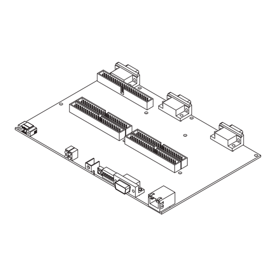
Figure 1 shows the NI sbRIO-961x/9612XT/963x/9632XT and the NI sbRIO-964x/9642XT. NI sbRIO-961x/9612XT/963x/9632XT NI sbRIO-964x/9642XT Figure 1. NI sbRIO-961x/9612XT/963x/9632XT and NI sbRIO-964x/9642XT What You Need to Get Started This section lists the software and hardware you need to start programming the NI sbRIO device. Software Requirements You need a development computer with the following software installed on it. - Page 3 Refer to the Understanding Ground Connections section for cautions about current loops through the grounding lug. Figure 2 shows the dimensions of the NI sbRIO-961x/9612XT/963x/ 9632XT/964x/9642XT. © National Instruments Corporation NI sbRIO-961x/9612XT/963x/9632XT/964x/9642XT...
- Page 4 5.550 (140.97) 5.415 (137.54) 12×Ø 0.134 (3.40) 4.400 (111.76) 2.440 (61.98) 2 mm Clearance Required Above This Capacitor 0.275 (6.99) 0.450 (11.43) 0.125 (3.18) 0.000 (0) 2 mm Clearance Required Above This Capacitor 0.651 (16.54) 0.574 (14.58) 0.327 (8.31) 0.000 (0) –0.110 (2.79) Minimum Clearance Needed Below Board...
- Page 5 To maintain isolation clearances on the C Series modules, do not use mounting hardware larger than 0.240 in. (6.1 mm) in diameter and maintain an air gap of at least 0.200 in. (5.0 mm) from the modules to anything else. © National Instruments Corporation NI sbRIO-961x/9612XT/963x/9632XT/964x/9642XT...
- Page 6 I/O and Other Connectors on the NI sbRIO Device Figure 4 shows the locations of parts on the NI sbRIO device. 1 J10, Connector for C Series Module 3 11 J2, RJ-45 Ethernet Port 2 Plated Mounting Holes 12 J1, RS-232 Serial Port 3 J7, Analog I/O Connector 13 DIP Switches 4 J9, Connector for C Series Module 2...
- Page 7 J5 to accommodate for the height of the J5 connector. † Use Samtec connector ESW-117-33-S-D if you are connecting one board to J6 and J5 to (NI sbRIO-964x/9642XT Only) accommodate for the height of the J5 connector. © National Instruments Corporation NI sbRIO-961x/9612XT/963x/9632XT/964x/9642XT...
- Page 8 The following figures show the pinouts of the I/O connectors on the NI sbRIO devices. D GND 50 49 Port2/DIO8 48 47 D GND Port2/DIO7 D GND 46 45 Port2/DIO6 D GND 44 43 Port2/DIO5 D GND 42 41 Port2/DIO4 D GND 40 39 Port6/DIO8...
- Page 9 14 13 D GND Port8/DIO0 Port8/DIOCTL 12 11 Port8/DIO9 D GND Port7/DIO8 D GND Port7/DIO7 D GND Port7/DIO6 D GND Port7/DIO5 Port7/DIO4 D GND Figure 6. Pinout of I/O Connector P3, 3.3 V Digital I/O © National Instruments Corporation NI sbRIO-961x/9612XT/963x/9632XT/964x/9642XT...
- Page 10 50 49 D GND Port2/DIO3 D GND 48 47 Port2/DIO2 D GND 46 45 Port2/DIO1 D GND 44 43 Port2/DIO0 Port2/DIOCTL 42 41 Port2/DIO9 D GND 40 39 Port1/DIO8 D GND 38 37 Port1/DIO7 D GND 36 35 Port1/DIO6 D GND 34 33 Port1/DIO5 D GND...
- Page 11 14 13 D GND Port3/DIO0 Port3/DIOCTL 12 11 Port3/DIO9 D GND Port7/DIO3 D GND Port7/DIO2 D GND Port7/DIO1 Port7/DIO9 Port7/DIO0 Port7/DIOCTL D GND Figure 8. Pinout of I/O Connector P5, 3.3 V Digital I/O © National Instruments Corporation NI sbRIO-961x/9612XT/963x/9632XT/964x/9642XT...
- Page 12 AI GND Pin 1 AI GND AI10 AI11 AI GND AI12 AI13 Pin 50 AI GND AI14 AI15 AI GND AI16 AI24 AI25 AI17 AI GND AI18 AI26 AI27 AI19 AI GND AI20 AI28 AI29 AI21 AI GND AI22 AI30 AI31 AI23 AI SENSE...
- Page 13 18 17 DI15 Pin 34 DI14 16 15 DI13 DI12 14 13 DIa11 DI10 12 11 Pin 1 D GND Figure 10. Pinout of I/O Connector J6, 24 V Digital Input (NI sbRIO-964x/9642XT Only) © National Instruments Corporation NI sbRIO-961x/9612XT/963x/9632XT/964x/9642XT...
- Page 14 D GND DO31 DO15 DO30 DO14 DO29 DO13 DO28 DO12 DO27 DO11 DO26 DO10 DO25 DO24 DO23 DO22 DO21 DO20 DO19 DO18 DO17 Pin 37 DO16 Pin 1 Figure 11. Pinout of I/O Connector J5, 24 V Digital Output (NI sbRIO-964x/9642XT Only) Figure 12 shows the signals on J1, the RS-232 serial port.
- Page 15 To prevent data loss and to maintain the integrity of your Ethernet installation, do not use a cable longer than 100 m. If you need to build your own cable, refer to the Cabling section for more information about Ethernet cable wiring connections. © National Instruments Corporation NI sbRIO-961x/9612XT/963x/9632XT/964x/9642XT...
- Page 16 The host computer communicates with the device over a standard Ethernet connection. If the host computer is on a network, you must configure the device on the same subnet as the host computer. If neither the host computer nor the device is connected to a network, you can connect the two directly using a crossover cable.
- Page 17 You can configure the device to launch an embedded stand-alone LabVIEW RT application each time it is booted. Refer to the Running a Stand-Alone Real-Time Application (RT Module) topic of the LabVIEW Help for more information. © National Instruments Corporation NI sbRIO-961x/9612XT/963x/9632XT/964x/9642XT...
-
Page 18: Boot Options
Boot Options Table 2 lists the reset options available on NI sbRIO devices. These options determine how the FPGA behaves when the device is reset in various conditions. Use the RIO Device Setup utility to select reset options. Access the RIO Device Setup utility by selecting Start»All Programs»National Instruments»NI-RIO»RIO Device Setup. -
Page 19: Configuring Dip Switches
6 NO FPGA Figure 14. DIP Switches All of the DIP switches are in the OFF (up) position when the NI sbRIO device is shipped from National Instruments. SAFE MODE Switch The position of the SAFE MODE switch determines whether the embedded LabVIEW Real-Time engine launches at startup. - Page 20 CONSOLE OUT Switch With a serial-port terminal program, you can use the serial port to read the IP address and firmware version of the NI sbRIO device. Use a null-modem cable to connect the serial port on the device to a computer. Push the CONSOLE OUT switch to the ON position.
-
Page 21: Using The Reset Button
You can define the USER LED to meet the needs of your application. To define the LED, use the RT LEDs VI in LabVIEW. For more information about the RT LEDs VI, refer to the LabVIEW Help. © National Instruments Corporation NI sbRIO-961x/9612XT/963x/9632XT/964x/9642XT... - Page 22 Modify the VI as necessary to solve the memory usage issue. Continuous The device has detected an unrecoverable error. flashing or solid Format the hard drive on the device. If the problem persists, contact National Instruments. NI sbRIO-961x/9612XT/963x/9632XT/964x/9642XT ni.com...
- Page 23 If the device is restored to the factory network settings, the LabVIEW run-time engine does not load. You must reconfigure the network settings and reboot the device for the LabVIEW run-time engine to load. © National Instruments Corporation NI sbRIO-961x/9612XT/963x/9632XT/964x/9642XT...
- Page 24 Integrated 3.3 V Digital I/O The four 50-pin IDC headers, P2–P5, provide connections for 110 low-voltage DIO channels, 82 D GND, and eight +5 V voltage outputs. Figure 16 represents a single DIO channel. +5 V User Xilinx Spartan-3 FPGA Connection U1: 5 V to 3.3 V Level Shifter, SN74CBTD3384CDGV from Texas Instruments D1 and D2: ESD-Rated Protection Diodes, NUP4302MR6T1G from ON Semiconductor...
-
Page 25: Signal Integrity
P2–P5. Each pin on the headers is rated for 2 A, but a typical 28 AWG ribbon cable is rated for only 225 mA per conductor. The OEM user is responsible for determining cabling requirements and ensuring that current limits are not exceeded. © National Instruments Corporation NI sbRIO-961x/9612XT/963x/9632XT/964x/9642XT... - Page 26 Integrated Analog Input Connector J7 provides connections for 32 single-ended analog input channels or 16 differential analog input channels. Connector J7 also provides one connection for AI SENSE and nine connections for AI GND. Refer to the I/O and Other Connectors on the NI sbRIO Device section for a pinout of connector J7.
- Page 27 Figure 18 shows how to make a differential connection for a floating signal and for a ground-referenced signal. Floating Grounded Signal Source Signal Source AI– – – AI– – – AI GND AI GND = 100 kΩ – 1 MΩ Figure 18. Differential Analog Input Connection © National Instruments Corporation NI sbRIO-961x/9612XT/963x/9632XT/964x/9642XT...
- Page 28 Referenced Single-Ended (RSE) Measurements You can use an RSE measurement configuration to take measurements on 32 channels when all channels share a common ground. Figure 19 shows how to make an RSE analog input connection for a floating signal. National Instruments does not recommend making an RSE connection for a ground-referenced signal.
- Page 29 NI 9263. Refer to the Specifications section for more information about power-on voltage. Refer to the software help for information about configuring startup output states in software. © National Instruments Corporation NI sbRIO-961x/9612XT/963x/9632XT/964x/9642XT...
- Page 30 Connect the positive lead of the load to the AO terminal. Connect the ground of the load to an AO GND terminal. Figure 22 shows a load connected to one analog input channel. Load AO GND Figure 22. Load Connected to One Analog Input Channel Integrated 24 V Digital Input (NI sbRIO-964x/9642XT Only) Connector J6 of the NI sbRIO-964x/9642XT provides connections for...
- Page 31 Refer to the Specifications section for the output specifications. The 24 V digital outputs of the NI sbRIO-964x/9642XT require a 6–35 VDC power supply separate from the power supply connected to J3. © National Instruments Corporation NI sbRIO-961x/9612XT/963x/9632XT/964x/9642XT...
- Page 32 Connect the device to DO and D GND, and connect the external power supply to V and D GND, as shown in Figure 24. 6– 35 VDC External Power – Device Supply D GND Figure 24. Device Connected to One Digital Output Channel Increasing Current Drive If you do not modify the NI sbRIO device, each channel has a continuous output current of 250 mA.
- Page 33 U112 28, 29 U111 30, 31 U110 The 20 A total-current limit is based on the maximum current rating of the DSUB connector pins, 5 A, multiplied by 4, the number of V pins. © National Instruments Corporation NI sbRIO-961x/9612XT/963x/9632XT/964x/9642XT...
- Page 34 Protecting the NI sbRIO Device from Flyback Voltages If a digital output channel is switching an inductive or energy-storing device such as a motor, solenoid, or relay, and the device does not have flyback protection, install a flyback diode as shown in Figure 26. 6–35 VDC External Power...
-
Page 35: Specifications
Data bits ..........5, 6, 7, 8 Stop bits..........1, 2 Parity ............Odd, Even, Mark, Space, None Flow control ........... RTS/CTS, XON/XOFF, DTR/DSR, None Processor Speed NI sbRIO-9611/9631/9641 ....266 MHz NI sbRIO-9612/9632/9642 and NI sbRIO-96x2XT........400 MHz © National Instruments Corporation NI sbRIO-961x/9612XT/963x/9632XT/964x/9642XT... - Page 36 Memory Nonvolatile memory NI sbRIO-9611/9631/9641....128 MB minimum NI sbRIO-9612/9632/9642 and NI sbRIO-96x2XT ......256 MB minimum System memory NI sbRIO-9611/9631/9641....64 MB minimum NI sbRIO-9612/9632/9642 and NI sbRIO-96x2XT ......128 MB minimum For information about the life span of the nonvolatile memory and about...
- Page 37 Maximum hold current at 70 °C ..20 mA Maximum hold current at 85 °C (NI sbRIO-96x2XT only)....3 mA Trip current at 25 °C ....... 71 mA Resistance at 25 °C ......33 Ω ±20% © National Instruments Corporation NI sbRIO-961x/9612XT/963x/9632XT/964x/9642XT...
- Page 38 Resistance-temperature characteristics, typical curve Resistance-Temperature Characteristics Typical Curve 1000 –40 –20 Temperature (°C) NI sbRIO-961x/9612XT/963x/9632XT/964x/9642XT ni.com...
-
Page 39: Analog Input
Non-adjacent channels ....–70 dB Small-signal bandwidth......700 kHz Overvoltage protection AI channel (0 to 31) ......±24 V (one channel only) AISENSE ........±24 V CMRR (DC to 60 Hz) ......92 dB © National Instruments Corporation NI sbRIO-961x/9612XT/963x/9632XT/964x/9642XT... - Page 40 Typical performance graphs Settling Error Versus Time for Different Source Impedances 10 k 10 kΩ 5 kΩ 2 kΩ 1 kΩ ≤100 Ω Time (μs) AI <0..31> Small Signal Bandwidth –2 –4 –6 –8 –10 –12 –14 10 k 100 k 1000 k 10000 k Frequency (Hz)
- Page 41 (μV) ±10 7,820 36.6 52.0 97.6 ±5 3,990 18.6 26.4 48.8 ±1 4.27 6.07 12.0 ±0.2 1.37 1.96 Sensitivity is the smallest voltage change that can be detected. It is a function of noise. © National Instruments Corporation NI sbRIO-961x/9612XT/963x/9632XT/964x/9642XT...
- Page 42 Accuracy details Residual Gain Residual Offset Error Gain Offset Error Tempco INL Error Nominal (ppm of Tempco Reference (ppm of (ppm of (ppm of Range (V) Reading) (ppm/°C) Tempco Range) Range/°C) Range) ±10 ±5 ±1 ±0.2 Absolute accuracy formulas AbsoluteAccuracy = Reading · GainError + Range · OffsetError + NoiseUncertainty GainError = ResidualGainError + GainTempco ·...
-
Page 43: Analog Output
Calibrated, typ (25 °C, ±5 °C) 0.01% 0.1% Uncalibrated, max (–40 to 85 °C) 2.2% 1.7% Uncalibrated, typ (25 °C, ±5 °C) 0.3% 0.25% * Range equals ±10.7 V Stability Offset drift........80 μV/°C Gain drift......... 6 ppm/°C © National Instruments Corporation NI sbRIO-961x/9612XT/963x/9632XT/964x/9642XT... - Page 44 Protection Overvoltage ........±25 V at 25 °C Short-circuit........Indefinitely Power-on voltage ........0 V Note All analog outputs are unpowered until a value is written to an analog output. Update time One channel in use......3 μs Two channels in use ......5 μs Three channels in use ......7.5 μs Four channels in use ......9.5 μs Noise...
- Page 45 Setup time is the amount of time input signals must be stable before you can read from the module. Transfer time is the maximum time FPGA Device I/O functions take to read data from the module. Refer to the Increasing Current Drive section for information about installing heat sinks. © National Instruments Corporation NI sbRIO-961x/9612XT/963x/9632XT/964x/9642XT...
-
Page 46: Power Limits
Maximum total output current on all channels ........20 A ) ......0.3 Ω max Output impedance (R Continuous overvoltage protection range (V )......40 V Reversed-voltage protection ....None Current limiting ........None Short-circuit protection......Indefinitely protected when a channel is shorted to D GND or to a voltage up to V Trip current for one channel With all other channels... - Page 47 = Total DIO Current × 3.3 V/0.85 Maximum P ........11.1 W = Total 5 V Output Current × 5 V/0.9 Maximum P ........3.3 W; each installed C Series CSer module consumes up to 1.1 W. © National Instruments Corporation NI sbRIO-961x/9612XT/963x/9632XT/964x/9642XT...
-
Page 48: Safety Voltages
Example power requirement calculations: • For an NI sbRIO-9642/9642XT with three installed board-only C Series modules, 20 mA total current through the 3.3 V DIO pins, and 1 A of current through the 5 V output, calculate the total power requirement as follows: = 8.00 W = 3.30 W... -
Page 49: Environmental Management
Caution Measurement Categories II, III, or IV. Environmental Management National Instruments is committed to designing and manufacturing products in an environmentally responsible manner. NI recognizes that eliminating certain hazardous substances from our products is beneficial to the environment and to NI customers. -
Page 50: Physical Characteristics
Environmental The NI sbRIO-96xx/96x2XT is intended for indoor use only. Ambient temperature in enclosure (IEC 60068-2-1, IEC 60068-2-2) NI sbRIO-961x/963x/964x....–20 to 55 °C NI sbRIO-96x2XT ......–40 to 85 °C Storage temperature (IEC 60068-2-1, IEC 60068-2-2) ...–40 to 85 °C Operating humidity (IEC 60068-2-56) ........10 to 90% RH, noncondensing Storage humidity (IEC 60068-2-56)..5 to 95% RH, noncondensing Maximum altitude........2,000 m... - Page 51 Connector 1 Connector 2 Pin 1 Pin 8 Pin 1 Pin 8 Figure 27. Ethernet Connector Pinout © National Instruments Corporation NI sbRIO-961x/9612XT/963x/9632XT/964x/9642XT...
-
Page 52: Where To Go For Support
For patents covering National Instruments products/technology, refer to the appropriate location: Help»Patents in your software, the patents.txt file on your media, or the National Instruments Patent Notice at ni.com/patents.
Need help?
Do you have a question about the sbRIO-9611 and is the answer not in the manual?
Questions and answers