Table of Contents
Advertisement
Quick Links
Advertisement
Table of Contents

Related Manuals for Air Lift Load Controller II 25812


Summary of Contents for Air Lift Load Controller II 25812
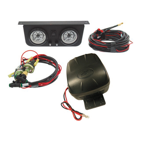
- Page 1 Kit 25812 5 psi Low Pressure ™ Sensor (Dual Gauge) INSTALLATION GUIDE For maximum effectiveness and safety, please read these instructions completely before proceeding with installation. Failure to read these instructions can result in an incorrect installation.
-
Page 3: Table Of Contents
TABLE OF CONTENTS Introduction ........2 Important Safety Notice . -
Page 4: Introduction
Air Lift Company reserves the right to make changes and improvements to its products and publications at any time. Contact Air Lift Company at (800) 248-0892 or visiti us online at www.airliftcompany.com for the latest version of this manual. -
Page 5: Installation Diagram
Harness #1 ........1 24561 Fuse adapter ........ 1 26110 Harness #2 ........1 24643 Red wire........16’ 20225 Hose..........25’ 20788 Black wire ........8’ Missing or damaged parts? Call Air Lift customer service at (800) 248-0892 for a replacement part. MN-337... -
Page 6: Installing The Load Controller Ii System
Air Lift customer service at (800) 248-0892. If you are adding this control system to an Air Lift SuperDuty application, then no modifications to the low pressure sensor are necessary. If you are adding this control system to an Air Lift 1000 or RideControl application, and if your specific application requires a minimum of 10 p.s.i., then it will be necessary to adjust the low pressure sensor to 10 p.s.i. -
Page 7: Step By Step Installation
Load Controller II STEP BY STEP INSTALLATION All of the electrical connections are matched by male-to-female push-in terminals. All of the air line connections will be white- to-white, no tape-to-no tape, indicated by the color band. The color band also serves as a reference point for installing the air line into the fitting. Properly installed, the front edge of the color band should be against the collar of the fitting (fig. - Page 8 Load Controller II TO PREVENT THE ELEMENTS FROM ENTERING THE CAB AREA. Frame Floor plan Compressor Compressor L-bracket fig. 6 Supplied self tapping screw ¼” Bolt and nut will need to be provided if the L-bracket is fabricated. 3. Connect wiring harness #1 to the back of the gauge panel. a.
- Page 9 Load Controller II b. In some cases, a hole may have to be drilled to allow access for the harness. Drill a 1” diameter hole and install the provided grommet (fig. 8). It will be necessary to seal any grommets or holes that have been cut, drilled or removed so as not to allow elements to enter the cab area of the vehicle.
-
Page 10: Warranty And Returns Policy
Air Lift at (800) 248-0892 in the U.S. and Canada (elsewhere, (517) 322-2144) for a Returned Materials Authorization (RMA) number. Returns to Air Lift can be sent to: Air Lift Company • 2727 Snow Road • Lansing, MI • 48917. -
Page 11: Replacement Information
**formerly EasyStreet Replacement Information If you need replacement parts, contact the local dealer or call Air Lift customer service at (800) 248-0892. Most parts are immediately available and can be shipped the same day. Contact Air Lift Company customer service at (800) 248-0892, first if: •... - Page 12 Thank you for purchasing Air Lift products — the professional installer’s choice! Air Lift Company • 2727 Snow Road • Lansing, MI 48917 or PO Box 80167 • Lansing, MI 48908-0167 Toll Free (800) 248-0892 • Local (517) 322-2144 • Fax (517) 322-0240 • www.airliftcompany.com...
Need help?
Do you have a question about the Load Controller II 25812 and is the answer not in the manual?
Questions and answers