Table of Contents
Advertisement
Advertisement
Table of Contents

Related Manuals for Air Lift 3H


Summary of Contents for Air Lift 3H
- Page 1 Air Lift Performance 3H Height ™ Upgrade Kit 27705 INSTALLATION GUIDE For maximum effectiveness and safety, please read these instructions completely before proceeding with installation. Failure to read these instructions can result in an incorrect installation.
- Page 2 Download the App for the Best #lifeonair The Air Lift Performance 3 mobile app allows for full integration of your new 3H/3P control system on compatible mobile devices. Simply download the FREE app to not only take full control of your system, but to always have the latest system firmware with updates directly from the app.
-
Page 3: Table Of Contents
Notation Explanation ..........3 Installing the Air Lift Performance 3H Upgrade Kit ..4 Install Harness . -
Page 4: Component List
17497 Screw 10-16 x 1 3/4” Self Tapping Zinc ...8 26953-020 Harn-20FT FL Height Sensor* .... 1 Missing or damaged parts? Call Air Lift customer service at (800) 248-0892 for replacement parts. STOP! * FL = Front left corner RL = Rear left corner... -
Page 5: Introduction
The information includes step-by-step installation information, installation templates and a troubleshooting guide. Air Lift Company reserves the right to make changes and improvements to its Air Lift Performance products and publications at any time. For the latest version of this manual, contact Air Lift Company at (800) 248-0892 or visit airliftperformance.com. -
Page 6: Installing The Air Lift Performance 3H Upgrade Kit
Installation Manual Installing Air Lift Performance 3H Height Upgrade Kit INSTALL HARNESS The harness can be routed inside or underneath the vehicle. In either case, ensure all parts of the harness are protected from abrasive edges and heat sources. REMOVE ALL FUSES WHEN JUMP-STARTING OR WELDING ON THE VEHICLE. -
Page 7: Height Sensors
Installation Manual HEIGHT SENSORS Installation of height sensors is a trial-and-error process and requires patience. The goal is to use as much of the sensor range as possible which will maximize height adjustment accuracy. Determininig Height Sensor Mounting Point 1. Solid mounting point on the body or frame that will not deflect. Anything that moves is not a good mounting point. - Page 8 Installation Manual FLOOR JACKS CAN BE DANGEROUS. WHENEVER USING A FLOOR JACK, MAKE WARNING SURE IT IS RATED FOR THE LOAD IT IS LIFTING. CHECK THE VEHICLE OWNER’S MANUAL FOR INFORMATION ABOUT WHERE TO PLACE THE JACK. BEFORE RAISING THE VEHICLE, PLACE WHEEL CHOCKS IN FRONT AND BEHIND THE WHEELS TO PREVENT THE VEHICLE FROM ROLLING.
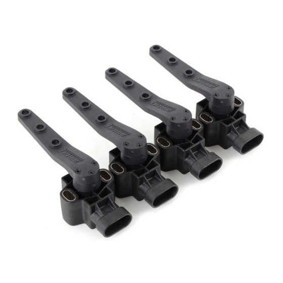
- Page 9 Installation Manual SELECTING SENSOR ARM HOLE Max angle of travel for this sensor is 120 degrees, which can be correlated to the necessary suspension travel as seen in the table below (table 1). Any significant over-extension or over-compression may damage and possibly destroy the sensor or sensor linkage. First hole Second hole Third hole fig.
-
Page 10: Installation Diagram
Installation Manual MN-947... - Page 11 Installation Manual Heat-shrinkable butt splice MN-947...
- Page 12 Installation Manual LINKAGE ASSEMBLY/MODIFICATION 1. Locate the linkage and ensure the rod is threaded all the way on (fig. 8). Thread both ends all the way down fig. 8 2. Next put the suspension in the mid-position with respect to full suspension travel (fig.
- Page 13 Installation Manual 6. Remove the rod linkage from the sensor arm and measure 1/2” back from the mark. This will show where to cut the rod (fig. 13). Mark Rod cover Cut here fig. 13 7. Before cutting the rod, thread the jam nut back on the rod. Use the nut to debur the rod end.
- Page 14 18 Arc for trimming CALIBRATION After installation of all the height sensors, run through the calibration setup again and this time select height sensors install when prompted. Details of this step can be found in the 3H User Guide. MN-947...
-
Page 15: Height Sensor Install Tool
Installation Manual Height Sensor Install Tool 120˚ 120˚ 100˚ 100˚ 80˚ 80˚ 60˚ 60˚ 120˚ 120˚ 100˚ 100˚ 80˚ 80˚ 60˚ 60˚ Cut out the height sensor tools and position each one as shown at right depending on the height sensor orientation. - Page 17 Installation Manual Notes MN-947...
- Page 18 Installation Manual Notes MN-947...
-
Page 19: Limited Warranty And Return Policy
Installation Manual Limited Warranty and Return Policy Air Lift Company provides a 1-year limited warranty to the original purchaser of Air Lift Performance damper kits from the date of original purchase, that the products will be free from defects in workmanship and materials when used on vehicles as specified by Air... -
Page 20: Need Help
Thank you for purchasing Air Lift Performance products! Air Lift Company • 2727 Snow Road • Lansing, MI 48917 or P.O. Box 80167 • Lansing, MI 48908-0167 Toll Free (800) 248-0892 • Local (517) 322-2144 • Fax (517) 322-0240 • airliftperformance.com...
Need help?
Do you have a question about the 3H and is the answer not in the manual?
Questions and answers