Table of Contents
Advertisement
GETTING STARTED GUIDE
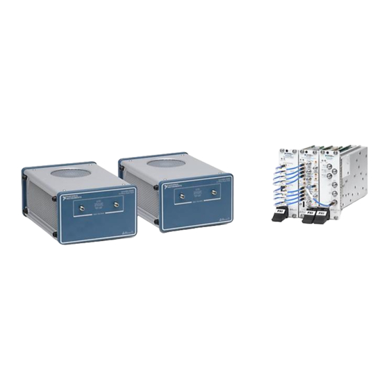
PXIe-5831
Up to 44 GHz, 1 GHz Bandwidth, Vector Signal Transceiver
Note
Before you begin, install and configure your chassis and controller.
This document explains how to install, configure, and test the PXIe-5831. The PXIe-5831 is a
half-duplex RF communications instrument with up to 1 GHz of instantaneous bandwidth,
designed for testing 5G mmWave components. You can program the PXIe-5831 instrument
using RFmx or NI-RFSA and NI-RFSG driver software.
The PXIe-5831 IF only instrument configuration comprises the following modules:
•
PXIe-5820 Vector Signal Transceiver
•
PXIe-3622 Vector Signal Up/Down Converter
The PXIe-5831 IF and mmWave instrument configuration comprises the following modules:
•
PXIe-5820 Vector Signal Transceiver
•
PXIe-3622 Vector Signal Up/Down Converter
•
PXIe-5653 RF Analog Signal Generator (LO source)
•
One or two mmRH-5582 mmWave Radio Heads
There is no single instrument labeled "PXIe-5831."
Contents
Verifying the System Requirements..........................................................................................2
Unpacking the Kit..................................................................................................................... 2
Verifying the Kit Contents................................................................................................ 2
Preparing the Environment....................................................................................................... 4
Choosing and Installing the Software....................................................................................... 6
Software Options...............................................................................................................6
Installing the Software...................................................................................................... 6
Installing the PXIe-5831........................................................................................................... 7
Interconnecting the PXIe-5831 Modules.......................................................................... 9
Connecting mmWave Radio Heads................................................................................ 12
Configuring the PXIe-5831 in MAX...................................................................................... 15
Self-Calibration....................................................................................................................... 16
Performing a Self-Calibration Using NI-RFSA..............................................................16
Locating the Software and Examples......................................................................................18
Software Locations......................................................................................................... 18
Programming Examples Locations................................................................................. 20
Making a First Measurement.................................................................................................. 21
Advertisement
Table of Contents

Related Manuals for NI PXIe-5831


Summary of Contents for NI PXIe-5831
-
Page 1: Table Of Contents
Note Before you begin, install and configure your chassis and controller. This document explains how to install, configure, and test the PXIe-5831. The PXIe-5831 is a half-duplex RF communications instrument with up to 1 GHz of instantaneous bandwidth, designed for testing 5G mmWave components. You can program the PXIe-5831 instrument using RFmx or NI-RFSA and NI-RFSG driver software. -
Page 2: Verifying The System Requirements
Worldwide Support and Services.................... 37 Verifying the System Requirements To use the PXIe-5831, your system must meet certain requirements. For more information about minimum system requirements, recommended system, and supported application development environments (ADEs), refer to the readme, which is installed or available at ni.com/manuals. - Page 3 MMPX (m)-to-MMPX (m) cable, 200 mm – MMPX (m)-to-MMPX (m) cable, 152 mm (x8) – MMPX (m)-to-SMA (m) cable, 152 mm (x2) – Mini HDMI-to-Mini HDMI cable • AC power supply adapter for mmRH-5582 PXIe-5831 Getting Started Guide | © National Instruments | 3...
-
Page 4: Preparing The Environment
Optional Items • A 0.9 N · m (8 lb · in.) calibrated torque wrench, 5/16 in. (NI part number 751120-01). Preparing the Environment Ensure that the environment you are using the PXIe-5831 in meets the following specifications. - Page 5 Clean the hardware with a soft, nonmetallic brush or lint free cloth. Make sure that the hardware is completely dry and free from contaminants before returning it to service. Note Refer to the PXIe-5831 Specifications at ni.com/manuals for complete specifications. PXIe-5831 Getting Started Guide | © National Instruments | 5...
-
Page 6: Choosing And Installing The Software
Related Information Refer to the RFmx SpecAn Help, the RFmx Demod Help, the NI RF Vector Signal Analyzers Help, or the NI RF Signal Generators Help for more information about using the RFmx, NI- RFSA, and NI-RFSG instrument driver FPGA extensions. -
Page 7: Installing The Pxie-5831
Install the driver software using NI Package Manager or by inserting your driver software media into your computer. If you do not already have NI Package Manager installed, visit ni.com/r/NIPMDownload to download NI Package Manager. Refer to the NI Package Manager Manual... - Page 8 5. PXI Express Peripheral Slot 3. PXI Express Hybrid Peripheral Slot The modules that comprise the PXIe-5831 can be placed in PXI Express peripheral slots, PXI Express hybrid peripheral slots, or PXI Express system timing slots. Touch any metal part of the chassis to discharge static electricity.
-
Page 9: Interconnecting The Pxie-5831 Modules
Incorrect torque at SMA connections can damage device connectors and degrade signal fidelity. Connecting the PXIe-5820 and PXIe-3622 Complete the following steps for the baseband signal connections and Reference Clock connection, as shown in the following figure. PXIe-5831 Getting Started Guide | © National Instruments | 9... - Page 10 I/Q IN I+ I/Q OUT I- I/Q IN I- I/Q OUT Q+ I/Q IN Q+ I/Q OUT Q- I/Q IN Q- I/Q IN I+ I/Q OUT I+ I/Q IN I- I/Q OUT I- 10 | ni.com | PXIe-5831 Getting Started Guide...
- Page 11 1. MMPX (m)-to-SMA (m) Cable, 152 mm Use one of the 152 mm MMPX (m)-to-SMA (m) cables to connect the PXIe-3622 REF IN front panel connector to the PXIe-5653 REF OUT (10 MHz) front panel connector. PXIe-5831 Getting Started Guide | © National Instruments | 11...
-
Page 12: Connecting Mmwave Radio Heads
PXIe-5653 LO1 OUT front panel connector. Related Information Refer to the PXIe-5831 section of the NI RF Vector Signal Transceivers Help for more information about how to make connections using an external clock. Connecting mmWave Radio Heads Depending on the hardware configuration you purchased, complete this section to connect either one or two mmRH-5582 mmWave Radio Heads to the PXIe-5831. - Page 13 Connecting Two mmWave Radio Heads to the PXIe-5831 Prior to starting this procedure, connect the first mmWave radio head to your PXIe-5831 as directed in the Connecting One mmWave Radio Head to the PXIe-5831 section.
- Page 14 The connection is daisy chained on the back panel of the mmRH-5582. Connect the AC power supply adapter to the mmRH-5582 power input. Finger-tighten the locking screws on the power supply connector to the mmRH-5582 using a small flat blade screwdriver. 14 | ni.com | PXIe-5831 Getting Started Guide...
-
Page 15: Configuring The Pxie-5831 In Max
Direct Connections to the PXIe-5831 The PXIe-5831 is a precision RF instrument that is sensitive to ESD and transients. Ensure you are making proper direct connections to the PXIe-5831 to avoid damaging the hardware. Notice Apply external signals only while the hardware is powered on. Applying external signals while the hardware is powered off may cause damage. -
Page 16: Self-Calibration
Self-test the hardware by selecting the item in the configuration tree and clicking Self- Test in the MAX toolbar. Repeat this step for all modules in your PXIe-5831 system. The MAX self-test performs a basic verification of hardware resources. - Page 17 Select the device identifier assigned to the PXIe-3622 in MAX in the [Resource Name] drop-down menu. Set Clock Source to OnboardClock. Set Self Calibration Step Operations to Perform All Self Calibration Steps. Run the VI. PXIe-5831 Getting Started Guide | © National Instruments | 17...
-
Page 18: Locating The Software And Examples
Windows 10 (32-bit)/8.1 (32-bit)/7 (32-bit)- Program Files\National Instruments • Windows 10 (64-bit)/8.1 (64-bit)/7 (64-bit)- Program Files (x86)\National Instruments Microsoft .NET For the location of .NET class libraries, refer to the installed RFmx readme. 18 | ni.com | PXIe-5831 Getting Started Guide... - Page 19 Microsoft .NET Use the NI-RFSA .NET class library by adding a reference to NationalInstruments.ModularInstruments. NIRfsa.Fx40 NationalInstruments.ModularInstruments. and any dependent class libraries from NIRfsa.Fx45 within the Solution Explorer in Visual Studio. PXIe-5831 Getting Started Guide | © National Instruments | 19...
-
Page 20: Programming Examples Locations
Solution Explorer in Visual Studio. Programming Examples Locations Using the NI Example Finder If you are using RFmx, NI-RFSA, or NI-RFSG with LabVIEW or LabWindows/CVI, use the NI Example Finder to locate programming examples. Launch LabVIEW or LabWindows/CVI. -
Page 21: Making A First Measurement
Navigate to Hardware Input and Output»Modular Instruments. Open the example that best matches your application requirements. Using Microsoft Visual C/C++ If you are using RFmx or NI-RFSA with Microsoft Visual C/C++, locate examples in the following directories. Table 6. Location of Microsoft Visual C/C++ Programming Examples... -
Page 22: Troubleshooting
Troubleshooting If an issue persists after you complete a troubleshooting procedure, contact NI technical support or visit ni.com/support. What Should I Do if the PXIe-3622 Does Not Appear in MAX? In the MAX configuration tree, expand Devices and Interfaces. Expand the Chassis tree to see the list of installed hardware, and press <F5> to refresh the list. -
Page 23: What Should I Do If The Module Fails The Self-Test
What Should I Do if the Instrument Does Not Initialize? Failure to initialize may indicate a problem with module interconnections or with MAX. If the niRFSA Initialize VI or niRFSG Initialize VI returns an error and the PXIe-5831 fails to initialize, complete the following steps: Reconnect the PXIe-5831 front panel cables securely. -
Page 24: Hardware Connectors And Indicators
REF IN Input connector that allows for the use of an external 10 MHz MMPX (f) Reference Clock. REF OUT Output connector that can export a 10 MHz Reference Clock. MMPX (f) 24 | ni.com | PXIe-5831 Getting Started Guide... - Page 25 I/Q IN Input connector for I+ signals. MMPX (f) Input connector for I- signals. MMPX (f) Input connector for Q+ signals. MMPX (f) Input connector for Q- signals. MMPX (f) PXIe-5831 Getting Started Guide | © National Instruments | 25...
- Page 26 The indicators are listed in increasing order of priority. For example, if you are generating a waveform using NI-RFSG and waiting on an acquisition Reference Trigger in NI-RFSA, the LED is dim amber. 26 | ni.com | PXIe-5831 Getting Started Guide...
- Page 27 MGT REF– / DIO 1 DIO 3 MGT Rx+ 2 MGT Tx+ 2 MGT Rx– 2 MGT Tx– 2 MGT Rx+ 3 MGT Tx+ 3 MGT Rx– 3 MGT Tx– 3 5.0 V Reserved PXIe-5831 Getting Started Guide | © National Instruments | 27...
-
Page 28: Pxie-3622 Front Panel And Leds
Connector Type I/Q IN Input connector for I+ signals. MMPX (f) Input connector for I- signals. MMPX (f) Input connector for Q+ signals. MMPX (f) Input connector for Q- signals. MMPX (f) 28 | ni.com | PXIe-5831 Getting Started Guide... - Page 29 AUX 0 Reserved for internal use. MMPX (f) LO1 0 mmWave Output connector that routes a local oscillator SMA 27 GHz (f) signal to a mmWave radio head. PXIe-5831 Getting Started Guide | © National Instruments | 29...
- Page 30 • GREEN—The module is ready to be programmed by software. ACTIVE • OFF—The module is idle. • RED—The module detected an error state. 30 | ni.com | PXIe-5831 Getting Started Guide...
-
Page 31: Pxie-5653 Front Panel And Leds
Routes a frequency reference signal from the synthesizer/LO module onboard 10 MHz oven-controlled crystal oscillator (OCXO). REF OUT (100 MHz) Routes a frequency reference signal from the synthesizer/LO module onboard 100 MHz OCXO. PXIe-5831 Getting Started Guide | © National Instruments | 31... - Page 32 RED—The module detected an error state. An error state may indicate the module exceeded approved operating temperature and thermal shutdown occurred or that the module detected a power supply failure. If the power supply fails, contact NI technical support. 32 | ni.com | PXIe-5831 Getting Started Guide...
-
Page 33: Mmrh-5582 Front Panel, Back Panel, And Leds
50 Ω 2.4mm RX INPUT MAX POWER REF PWR ≤+30 dBm PMAX = REF PWR +6 dB REF PWR >+30 dBm PMAX =+36 dBm SWITCHED TRX PORTS DIRECT TRX PORT PXIe-5831 Getting Started Guide | © National Instruments | 33... - Page 34 SWITCHED TRX PORTS Bi-directional connector for both 2.4 mm (f), 50 Ω (0 through 7 or 0 through 15 on input and output of RF signals. modules labeled with SWITCHED TRX PORTS only) 34 | ni.com | PXIe-5831 Getting Started Guide...
- Page 35 IF OUT mmWave 0 or 1 connector on the PXIe-3622. Power Power supply input. MINI-COMBICON DIO IN Digital input/output control. Mini HDMI DIO OUT Digital input/output control for daisy chaining to adjacent Mini HDMI mmWave radio heads. PXIe-5831 Getting Started Guide | © National Instruments | 35...
- Page 36 RED—The module has encountered a hardware setup error or the module is exceeding approved operating temperature and is in a state of thermal shutdown. Related Information Refer to the PXIe-5831 Specifications for more information about front panel connectors and LEDs. 36 | ni.com | PXIe-5831 Getting Started Guide...
-
Page 37: Where To Go Next
*This item is also installed with the driver software. † The VST device information is also located in the NI RF Vector Signal Analyzer Help or the NI RF Signal Generators Help. The NI RF Vector Signal Transceivers Help, available at ni.com/manuals, is an HTML version of a traditional user manual that includes detailed information about RF fundamentals, device features, and programming for vector signal transceivers. - Page 38 . You can find patents.txt ni.com/patents information about end-user license agreements (EULAs) and third-party legal notices in the readme file for your NI product. Refer to the Export Compliance Information at for the NI global trade compliance policy and how ni.com/legal/export-compliance...
Need help?
Do you have a question about the PXIe-5831 and is the answer not in the manual?
Questions and answers