Table of Contents
Advertisement
Available languages
Available languages
Quick Links
Download this manual
See also:
User Manual
Advertisement
Table of Contents

Related Manuals for Lumel ND20


Summary of Contents for Lumel ND20
- Page 1 MIeRnIK pARAMeTRÓW SIeCI MeTeR OF neTWORK pARAMeTeRS ND20 InSTRUKCJA OBSŁUGI - SZYBKI START USeR’S MAnUAl - QUICK START Zeskanuj mnie Zeskanuj kod Scan the code pełna wersja instrukcji dostępna na Full version of user’s manual available at www.lumel.com.pl...
- Page 2 1. WYMAGANIA PODSTAWOWE, BEZPIECZEÑSTWO U¯YTKOWANIA W zakresie bezpieczeństwa użytkowania odpowiada wymaganiom normy PN-EN 61010-1. Uwagi dotyczące bezpieczeństwa: · Instalacji i podłączeń miernika powinien dokonywać wykwalifikowany personel. Należy wziąć pod uwagę wszystkie dostępne wymogi ochrony. · Przed włączeniem miernika należy sprawdzić poprawność połączeń. ·...
- Page 3 Rys. 1. Mocowanie miernika Rys. 2. Gabaryty miernika 3. OPIS PRZYRZ¥DU 3.1 Wejœcia pr¹dowe Wszystkie wejścia prądowe są izolowane galwanicznie (wewnętrzne przekładniki prądowe). Miernik przystosowany jest do współpracy z zewnętrznymi przekładnikami prądowymi pomiarowymi. Wyświetlane wartości prądów i wielkości pochodnych automatycznie przeliczane są o wielkość...
-
Page 4: Panel Przedni
Wielkości na wejściach napięciowych są automatycznie przeliczane o wielkość wprowadzonej przekładni zewnętrznego przekładnika na- pięciowego. Wejścia napięciowe określane są w zamówieniu jako 3 x 57.7/100 V, 3 x 230/400 V. 3.3 Schematy pod³¹czeñ Patrz rys.3 str. 32 4. PROGRAMOWANIE ND20 4.1 Panel przedni Rys.4. Panel przedni. - Page 5 3-fazowych mocy oraz THD (wiersz 4) 4.2 Komunikaty po wł¹czeniu zasilania Po włączeniu zasilania miernik wykonuje test wyświetlacza i wyświetla nazwę miernika ND20, wykonanie oraz aktualną wersję programu gdzie: n.nn jest numerem aktualnej wersji programu lub numerem wykonania specjal- nego.
- Page 6 (ALL – tablica 3 - patrz pełna wersja instrukcji obsługi dostępna na www.lumel.com.pl) w miejsce energii harmonicznej wyświetlane są wartości procentowe harmoniczych. Przyciskami można przełączać pomiędzy kolejnymi harmonicznymi. Nr harmonicznej wyświetlany jest na przemian z wartością. Poprzez interfejs RS-485 można ustawić...
- Page 7 , U/ THD U , I/ THD I Wyświetlane symbole -, kWh kVarh kVarh , U/ THD U , I/ THD I , U/ THD U , I/ THD I wiersz Uh1 V / Ih1 A/ Energia bierna THD1 % THD1 % Energia bierna indukcyjna...
- Page 8 Tablica 2a Wyświetlane symbole -, kWh kvar kvar Energia wiersz bierna Energia bierna Energia Energia indukcyjna pojemnościowa wiersz Wartości czynna czynna wyświetlane pobierana oddawana Energia Energia bierna wiersz bierna ujemna dodatnia Wyświetlanie opcja Wyświetlane symbole wiersz 1 P 3faz Wartości wiersz 2 miesiąc Q 3faz...
- Page 9 (punkt 6.5.1, pełna instrukcja obsługi na www.lumel.com.pl). Przykład wykorzystania przedstawiony jest w punkcie 6.5.3. pełnej instrukcji obsługi na www.lumel.com.pl. Załączenie alarmu sygnalizowane jest świeceniem napisu AL1 (w trybie A3non, A3nof, A3_on, A3_of: napisów AL1, AL2, AL3).
-
Page 10: Tryby Pracy
4.4 Tryby pracy Podane tablice znajdują się w pełnej instrukcji obsługi - dostępnej na www.lumel.com.pl Rys 6. Tryby pracy miernika ND20. -
Page 11: Ustawienia Parametrów
4.5 Ustawienia parametrów Do konfiguracji mierników ND20 przeznaczone jest bezpłatne oprogramowanie eCon dostępne na stronie www.lumel.com.pl. Rys 7. Menu setup Wejście w tryb programowania odbywa się poprzez naciśnięcie i przytrzymanie przycisku przez około 3 sekundy. Wejście w tryb programowania chronione jest kodem dostępu. W przypadku braku kodu, program przechodzi w opcje programowania. -
Page 13: Dane Techniczne
5. DANE TECHNICZNE Zakresy pomiarowe i dopuszczalne błędy podstawowe Tablica 3 ∑ Wielkość Zakres wskazań * Zakres Błąd podstawowy mierzona pomiarowy Prąd In 1 A 0,00 .. 12 kA 0,002 .. 1,200 A~ 0,2 % zak 0,00 .. 60 kA 0,010 .. - Page 14 Energia 0 ..99 999 999,9 0,5 % bierna kVarh pojemnościowa 0...100% 0...100 % 5 % zak *Zależnie od ustawionej przekładni tr_U (przekładnia przekładnika napięciowego: 0,1 .. 4000,0) oraz tr_I (przekładnia przekładnika prądowego: 1 .. 10000) w.m - błąd względem wartości mierzonej zak - błąd względem wartości zakresu Uwaga! Dla prawidłowego pomiaru prądu wymagana jest obecność...
- Page 15 - sygnał wejściowy: 0 .. 0,002..1,2In; 0,05..1,2Un dla prądu, napięcia 0 .. 0,002..1,2In; 0..0,1..1,2Un; dla współczynników PFi ,tji częstotliwość 47...63 Hz; sinusoidalny ( THD 8%) - współczynnik mocy: -1...0...1 - temperatura otoczenia: -25..23..+55 C - temperatura magazynowania: -30..+70 C - wilgotność: 25 ...
- Page 16 6. KOD WYKONAÑ Kod wykonań miernika parametrów sieci ND20. Tablica 4 MIERNIK PARAMETRÓW SIECI ND20 - X Prąd wejściowy In: 1 A (X/1) 5 A (X/5) Napięcie wejściowe (fazowe/międzyfazowe) Un: 3 x 57,7/100 V 3 x 230/400 V Wyjście analogowe prądowe: bez wyjścia analogowego...
-
Page 17: Basic Requirements And Operational Safety
INSTALLATION The ND20 meter is adapted to be fixed on a panel by means of holders. The fitting way is presented on the fig.1. Housing overall dimensions: 96 x 96 x 77 mm. At the rear side of the meter, there are screw terminal strips which enable the connection of external wires with a cross-section up to 2.5 mm... -
Page 18: Meter Description
Fig. 1. Meter fitting Fig. 2 Meter overall dimensions METER DESCRIPTION 3.1 Current Inputs All current inputs are galvanically isolated (internal current transfor- mers). The meter is adapted to co-operate with external measuring cur- rent transformers. Displayed current values and derivative quantities are automatically recoun in relation to the introduced external current transformer ratio. -
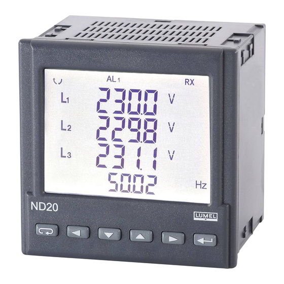
Page 19: Frontal Panel
ND20 PROGRAMMING 4.1 Frontal Panel Fig 4. Frontal panel Description of the frontal panel: 1 – abandon push-button – ESC 11 – units of displayed values 2 – push-button to displace to the left 12 – symbols of digital data 3 –... -
Page 20: Messages After Switching The Supply On
4.2 Messages after Switching the Supply on After switching the supply on, the meter performs the display test and display the ND20 meter name, rated current and voltage, the current program version, and next displays the measured values. where: n.nn is the number of... - Page 21 (starting from version 1.02). The error display is described in the chapter 8 of full version of user’s manual - available at www.lumel.com.pl. When displaying the reactive power, a marker indicating the load cha- racter is displayed, capacitive ( ) or inductive ( Displayed quantities in the field 9 (fig.
- Page 22 Backlit -, kWh symbols row 1 Uh1n* % Uh1n* % year cosinusj1 3phase exported imported harmonic harmonic Uh2n* % 1 Uh2n* % 1 cosinusj2 1 row 2 month active 3phase active. energy 1 energy 1 Uh3n* % 1 row 3 cosinusj3 1 Uh3n* % 1 3phase...
- Page 23 Table 2a Backlit symbols -, kWh kvar kvar reactive reactive capacitive row 1 inductive energy imported exported energy Displayed active row 2 active values reactive energy energy reactive negative positive row 3 energy energy Displaying optional Displayed symbols row 1 year P 3phase Displayed...
- Page 24 (section 6.5.1in the full version of user’s manual - available at www.lumel.com.pl.). The consumption example is presented in the section 6.5.3. - full version of user’s manual - available at www.lumel.com.pl.
-
Page 25: Operating Modes
4.4 Operating modes * The given tables can be found in the full user manual - available at www.lumel.com.pl Fig. 6. Operating modes of the ND20 meter. -
Page 26: Parameter Settings
4.5. Parameter Settings For the configuration of ND20 meters, the free eCon software is available at www.lumel.com.pl. Fig 7. Setup menu The entry in the programming mode is carried out through the pressure and holding down of the push-button during ca 3 sec. The entry in the programming mode is protected by the access code. -
Page 28: Technical Data
TECHNICAL DATA Measuring ranges and admissible basic errors Table 3 Measured Indication Measuring Basic value range* range error Current In 0.00 ... 12 kA 0.002 ... 1.200 A~ ±0.2% r 0.00 ... 60 kA 0.010 ... 6.000 A~ Voltage L-N 57.7 V 0.0 ... - Page 29 Power input: 6 VA - in supply circuit - in voltage circuit 0.05 VA 0.05 VA - in current circuit Display field: dedicated display LCD 3.5’’ Realay output: relay, voltageless NO contacts; load capacity 250 V~/ 0.5 A ~ Analog output: current 0(4) ...
- Page 30 - admissible peak factor: - current intensity 2 - voltage 2 - external magnetic field: 0...40...400 A/m - short duration overload (5 s) - voltage inputs : 2 Un (max.1000 V) - current inputs: 10 In - operating position: any - preheating time: 5 min.
-
Page 31: Ordering Codes
6. ORDERING CODES Table 4 Meter of network parameters ND20 - X Current input In: 1 A (X/1) 5 A (X/5) Voltage input (phase/phase-to-phase) Un: 3 x 57.7/100 V 3 x 230/400 V Analog current output: without analog output with programmable output 0(4) ... 20 mA Supply voltage: 85..253 V a.c., 90..300 V d.c. - Page 32 schematy podłączeń elecTrIcAl coNNecTIoNs Pomiar bezpośredni, półpośredni i pośredni jednofazowy Direct, semi-direct and indirect single-phase measurement Pomiar bezpośredni w sieci trójprzewodowej Direct measurement in a 3-wire network...
- Page 33 Pomiar półpośredni w sieci trójprzewo- dowej Semi-indirect measurement in a 3-wire network Pomiar pośredni z wykorzystaniem 2 przekładników prądowych i 2 lub 3 przekładników napięciowych w sieci trójprzewodowej Indirect measurement with the use of 2 current transformers and 2 or 3 voltage transformers in a 3- wire network...
- Page 34 Pomiar bezpośredni zasilanie rs 485 WYimp WYA1 GNDI w sieci czteroprzewo- dowej 23 22 17 16 Direct measurement ND20 in a 4-wire network. zasilanie rs 485 WYimp WYA1 GNDI Pomiar półpośredni w sieci czteroprzewodowej 23 22 17 16 ND20 Semi-indirect measurement...
- Page 35 WYA1 GNDI 23 22 17 16 ND20 Rys 3. Schematy podłączeń miernika w sieci: a) jednofazowej, b) trójfazowej - trójprzewodowej, c) trójfazowej - czteroprzewodowej Fig 3. Meter connection diagrams in a: a) single-phase network, b) 3-phase - 3 wire network,...
- Page 36 LUMEL S.A. ul. Sulechowska 1, 65-022 Zielona Góra, Poland tel.: +48 68 45 75 100, fax +48 68 45 75 508 www.lumel.com.pl Informacja techniczna: tel.: (68) 45 75 306, 45 75 180, 45 75 260 e-mail: sprzedaz@lumel.com.pl Realizacja zamówień: tel.: (68) 45 75 207, 45 75 209, 45 75 218, 45 75 341 fax.: (68) 32 55 650...
Need help?
Do you have a question about the ND20 and is the answer not in the manual?
Questions and answers