
Subscribe to Our Youtube Channel
Related Manuals for Lumel ND1


Summary of Contents for Lumel ND1
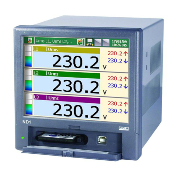
- Page 1 ANALYSER OF 3-PHASE POWER NETWORK PARAMETERS ND1 TYPE User’s Manual LZAE Lumel S. A. Sulechowska 1 65-022 Zielona Góra Poland (EU)
-
Page 2: Table Of Contents
2.2. PERATING AFETY 2.2.1. EMARKS ONCERNING THE NALYZER NSTALLATION 2.2.2. ESD P RECAUTIONS IN THE ROTECTION ANGE PREPARATION OF THE ND1 ANALYZER TO WORK 3.1. NPACKING 3.2. NSTALLATION IN THE ANEL 3.3. NALYZER PERATING ONDITIONS ANALYZER CONSTRUCTION 4.1. LCD S... - Page 3 OLORS OF EASURING ARAMETERS 5.2.1. RAPHIC IGNS 5.2.2. OLORS OF EASURING ALUES ANALYZER START 6.1. ONTEXT UTTON UNCTIONS 6.2. , ND1 C NTRY TO ARAMETER ONFIGURATION ONTROL ANEL INDOW CONFIGURATION OF ND1 7.1. ENERAL ETTINGS 7.1.1. ARAMETER ROGRAMMING ASIC 7.1.2.
- Page 4 7.6.1. ARAMETER ENERAL 7.6.2. ARAMETER CREENS 7.6.3. ARAMETER ROGRAMMING ANGES 7.6.4. ARAMETER ROGRAMMING 7.6.5. ARAMETER ROGRAMMING THER AUTO VIEWS 7.7. RCHIVIZATION 7.7.1. ROGRAMMING OF ROUP ARAMETERS 7.8. THERNET 7.9. ODBUS 7.9.1. ONFIGURATION OF ODBUS ASTER 7.9.2. CI1..24 ONFIGURATION OF INTERFACE INPUTS ENERAL AND EGISTER 7.9.3.
- Page 5 PROGRAMS ON THE PC 9.1. KD C ONNECT ROGRAM 9.1.1. USB D NSTALLATION OF THE RIVER 9.2. ND1 S ETUP PPLICATION 9.3. KD C HECK PPLICATION TECHNICAL DATA ORDER CODES MAINTENANCE AND GUARANTEE...
-
Page 6: Introduction
1. Introduction 1.1. Application The ND1 Power Quality Analyzer is destined for the measurement and analysis of 3-phase, 3 or 4-wire power network parameters, in balanced or unbalanced systems. 1.2. Analyzer Features Following features characterize the ND1 Power Quality Analyzer: ... -
Page 7: Firmware Update
The manufacturer reserves the right to a continuous improvement and makes changes in design and specifications in the product without warning. This especially concerns the internal device software (so called device firmware). The current software version and other files destined for the analyzer are available at our web page: http://www.lumel.com.pl... -
Page 8: General Information
2.2.1. Remarks Concerning the Analyzer Installation Various sources of noise occurring in practice interact with the ND1 Power Analyzer in a continuous or pulse way from the supply network side (as the result of the action of other devices) and also overlap on the measured signal or auxiliary circuits of the analyzer. - Page 9 In particular, strong pulse noises are dangerous for the device operation since they can cause sporadic erroneous measurement results or accidental operations of alarms. The level of these noises should be reduced to a value lower than the immunity threshold of the analyzer, first of all through a suitable installation of the analyzer in the object.
-
Page 10: P Recautions In The
2.2.2. Precautions in the ESD Protection Range Semiconductor elements or packages used in the analyzer design and marked with the sign as above, can be damaged in result of electrostatic discharges (ESD). In order to prevent this, you must observe following recommendations during service works: ... -
Page 11: Preparation Of The Nd1 Analyzer To Work
-20 ..+65ºC (-4 ...149ºF). 3.1. Unpacking A. Take the ND1 analyzer out from the shipping packing. The data plate with the version code, factory number and supply parameters are placed on the analyzer casing. Before unpacking, check the conformity of the device version with the order. -
Page 12: Analyzer Operating
Set of plugs 1 set CD with software and manuals 1 pc Power supply filter 1 pc Guarantee card 1 pc Note: Before unpacking the memory card carry away electrostatic charges from the body. 3.2. Installation in the Panel Fig. 3.1. Analyzer installation in the panel Put the seal from standard accessories on the casing (see section 3.1). -
Page 13: Analyzer Construction
4. Analyzer Construction Casing LED diode LCD screen Mounting brackets to fix the recorder in Door with lock (access to CF card the panel and USB socket) Fig. 4.1. Analyzer construction 4.1. LCD Screen with Touch Panel For the visualization of measuring data and the configuration of analyzer parameters, an LCD TFT 5.7”... - Page 14 External Substrate layer (glass) Fig. 4.2. Touch screen All elements of the user’s interface (windows, icons, buttons) have dimensions adapted to be easily handled by fingers – They do not require special tools. After mounting the analyzer into the panel, remove the foil protecting the external flexible layer of the touch panel if exist.
-
Page 15: Compact Flashm
(delivered in standard accessories) or another similar of maximum 3 m long. To gain access to the ND1 analyzer data thru USB interface on a PC with MS Windows operating system it is necessary to install drivers and the KD Connect program from the accompanied CD. -
Page 16: Terminal Plate
4.3. Terminal Plate Binary inputs (BI1..12), Alarm outputs (AL1..6), Analog outputs (AO1..4) Measuring package ND1 supply Object supplies RS485 and Ethernet interfaces... -
Page 17: Mounting Of Thep
Symbol of terminal Terminal description group Connection sockets of the measuring package (L1, L2, L3, N) Measured quantity: – current: 1 A or 5 A, – voltage: 57.7 V a.c. / 100 V a.c. or 230 V a.c. / 400 V a.c. or 400 V a.c. -
Page 18: Alarm Connection
Fig. 4.4. Connection of the power supply filter. 4.3.2. Alarm Connection, Binary Inputs and Analog Outputs Connection to terminals of the alarm system (electromechanical relays) AL1..6 Alarms are normally open contacts (NO). Parameters of the alarm system are given in the chapter “Technical Data". -
Page 19: C Onnection Of Communication Interfaces
(AT&T258) standard. To connect the analyzer with the hub (concentrator) or the switch, you have to use a cable with leads 1:1, according to the description as in the above figure. To the direct ND1 connection with the PC, use a crossed cable:... -
Page 20: Connection Ofm
1. To connect measuring signals use the plug-in strip from ND1 accessories 2. Signal connections are presented on figures in the view from the ND1 terminal plate side Fig. 4.5. Four-wire network. Indirect measurement with the use of 4 current transformers and 2 or 3 voltage transformers. - Page 21 Fig. 4.6. Three-phase network. Indirect measurement with the use of 2 current transformers and 2 or 3 voltage transformers. Fig. 4.7. Four-wire network. Indirect measurement with the use of 3 current transformers and 2 or 3 voltage transformers.
- Page 22 Fig. 4.8. Three-wire, three-phase network. Indirect measurement. Fig. 4.9. Three-wire, three-phase network. Indirect measurement.
- Page 23 Fig. 4.10. Four-wire network. Direct measurement. Fig. 4.11. Four-wire network. Semi-indirect measurement.
- Page 24 Fig. 4.12. Four-wire network. Indirect measurement with the use of 4 current transformers.
-
Page 25: Graphic Signs On The Analyzer Screen
5. Graphic Signs on the Analyzer Screen 5.1.1. Status Bar Change of data presentation form Automatic switching of screens The CF card status Alarms Parameter selection for visualization Parameter name Date Time Lack of CF card CF card partially filled Exceeded level storage over 90% of the card capacity 5.1.2. -
Page 26: Information Messages
Push-buttons for global copying of settings between menu windows Introduction of a number or string Option selection from the list or the dialogue Context help 5.1.3. Information Messages Warning Symbol of error occurrence Question Information icon 5.1.4. Dialogs Single and multiple selection. -
Page 27: Signs And Colors Ofm
Input numbers (float and integer numbers). String inputs (small and capital letters, numbers and special characters; password – replaced by dots) 5.2. Signs and Colors of Measuring Parameters 5.2.1. Graphic Signs Graphic signs used during the visualization process are presented below. (Note: some symbols occur only on selected screens). -
Page 28: Colors Of Measuringv
Alarm occurrence in a channel. This sign may be accompanied by one of the alarm type symbol. Signs of alarm types. Suitably: min, max, range off, range on alarm types. Incomplete measurement for the given time window or averaging range. State of binary inputs, suitably: input in the high state and input in the low state. -
Page 29: Analyzer Start
After touching the screen any place, the Context Menu appears. 6.1. Context Menu, Button Functions After pressing the screen during the visualization of measuring data, the Context Menu with the standard set of ND1 service options is displayed: Closing the Context Menu... - Page 30 Standard set of functions destined for the current operating of the ND1 analyzer: Selection of the screen kind for the presentation of analyzer measuring data. Switching of successive screens available for the selected type of data presentation. Selection of the log view for statistics, audits or alarms.
-
Page 31: Entry To Parameterc
6.2. Entry to Parameter Configuration, ND1 Control Panel Window In order to transit into ND1 parameter configuration, please select in the Context Menu the icon of ND1 analyzer configuration menu: Transition to the analyzer configuration menu The log in window appears. - Page 32 ND1 control panel. Open configuration The selection of the configuration file from stored files from file in the CompactFlash memory card. The ND1 Control Panel appears. It is the initial point for carrying out the full configuration of the ND1 analyzer.
-
Page 33: Configuration Of Nd1
7. Configuration of ND1 The ND1 Control Panel is the window in which all configuration parameters are grouped in different categories: – analyzer general settings, section 7.1 – input configuration, section 7.2 – alarm configuration, section 7.3 – analog output configuration, section 7.4 –... -
Page 34: General Settings
7.1. General Settings After pressing the icon configuration window basic parameters opens. They are symbol and analyzer description, selection of the menu language, setting of the date and time, capacity of event logs, service of the CF card, service of the LCD screen, setting of user messages and selection of the context menu option. - Page 35 7.1.2. Parameter Programming: LCD Screen Item Function Selection of the time to blank the LCD screen: switching off / 5 min…12 hours. Setting of the screen brightness Calibration of the touch screen (see section 8.2) Setting acceptance 7.1.3. Parameter programming: CompactFlash format Item Function CompactFlash Quick format (see...
-
Page 36: Inputs
7.1.4. Parameter programming: Other Item Function Edition 1…10 operator’s messages (see section 7.14) Selection of additional options for the Context Menu (see section 6.1) Setting acceptance 7.2. Inputs After pressing the icon the configuration window of the analyzer measuring input parameters becomes open (setting of the network base frequency, connection kind, current and voltage ratios, averaging periods, tariffs, quality of RMS voltage and frequency). -
Page 37: Parameter: Average
Item Function Input Power Card nominal values Selection of connection type: – 3-wire input – 4-wire input (3 + neutral wire) Edition of voltage ratio values Edition of current ratio values Setting acceptance Note: For a correct measurement of the zero current, you must prepare suitable terminal connections. - Page 38 7.2.3. Parameter programming: Tariffs Item Function Selection of the activation method: – Time trigger – Binary input Tariff settings 1..4: – Enabled / Disabled – Setting of the selected tariff trigger time Setting acceptance In case of tariff activation by binary inputs, a physical binary input from 1 to 4 corresponds to relevant tariff number.
-
Page 39: Alarms
Item Function On/Off energy log (active / reactive) Setting of the energy log updating frequency Setting acceptance 7.3. Alarms windows (1…12 alarms) After pressing the icon selection programming their parameters in General and Control tabs become open: Switching/selection Settings copying to another of alarm (1…12) alarm, here: 2..12 Note: only alarms from 1 to 6 have representation on physical outputs. - Page 40 3. Selection of alarm type: Min, Max, Range On, Range Off Min, Max - the alarm is enabled when a signal value is below/above the alarm value (Lower limit, Upper limit). Range On, Range Off – the alarm is enabled when the signal value is between or beyond set alarming values (Lower limit, Upper limit).
- Page 41 Edition of parameters for the chosen alarm hysteresis type: Hysteresis Type Percentage Value Percentage Value Off Percent Edition of the Edition in value In percentage percentage of the range of the range Hyst. Edition of the Edition of the value value in the value in the range unit...
- Page 42 Fig. 7.2. Functional diagram of the Value On alarm type Fig. 7.3. Functional diagram of the MAX alarm type taking in consideration the hysteresis of Value and Time type...
- Page 43 7.3.2. Parameter Programming: Control Switching/selection Setting copying to another of the alarm (1…12) alarm, here: 2.. 12 Description of the reference marks: 6. Selection of alarm Confirmation type: None Option disabled Latch The alarm state is supported in the analyzer as long as it will not be confirmed by the operator Accept Switching the alarm state off in the analyzer by the operator...
- Page 44 Alarm state Transition to browse the alarm log Entry in the alarm confirmation menu (protected by the user’s password) 7. Selection of the alarm locking source: None Option disabled BI1…BI12 Selection of binary input which the logic state 1 (ON) will lock the current state of the selected alarm 8.
-
Page 45: Analog Outputs
7.4. Analog Outputs After pressing the icon the window for the selection and configuration of 1…4 analog outputs become open. 7.4.1. Selection of the Analog Output 7.4.2. Parameter Programming: General Selection of the analog output <no.> Switching analog outputs (here: Analog output 1) - Page 46 Item Function Analog output selection from available :1..4 Edition of the analog output name Edition of the output description Signal source selection for the selected analog output Settings acceptance 7.4.3. Parameter Programming: Range Selection of the analog output Switching analog outputs <no.>...
-
Page 47: Power Quality
7.5. Power quality After pressing the icon the selection and configuration window of power quality parameters (General and Dips) opens. Power quality parameters are defined acc to the EN 50160 standard. 7.5.1. Parameter Programming: General Item Function 10 min. U RMS limits - Configuration of RMS voltage quality parameters for 10 minutes’... - Page 48 downwards for the selected probability – Max deviation (X%): admissible U RMS deviation percentage upwards for the selected probability – Default settings: manufacturer’s settings for the given parameter group 10 sec. frequency limits: configuration of frequency quality parameters for 10 seconds’ periods (default settings acc. to EN 50160): –...
- Page 49 Item Function Setting of the voltage dip threshold value and hysteresis in percentage of the nominal U RMS value Setting of the voltage flare threshold value and hysteresis in percentage of the nominal U RMS value Setting of the voltage decay threshold value and hysteresis in percentage of the nominal U MRS value Setting acceptance Power quality parameter definitions:...
-
Page 50: Visualization
Voltage swell – the temporary increase of the voltage RMS value in a grade exceeding the normally accepted tolerance interval (in reference to the rated or declared voltage). 7.6. Visualization After pressing the icon the window of selection and visualization parameter configuration of measurement result becomes open. -
Page 51: Parameter: Screens
Item Function Selection of colors for phase charts: – L1, L2, L3, N Selection of colors for line-to-line charts: – Color L1-2, L 2-3, L 3-1 Color selection for all remaining quantities Setting acceptance 7.6.2. Parameter: Screens Switching between available screens Parameter set selection Eneable/Disable the selected screen... - Page 52 – Power Quality view – Modubs Master state For each of these screen types, the dedicated group of parameters for them is available. You can select from this group one for the presentation. Large digital view Selection of data group for Selection of screen Alarm state presentation...
- Page 53 Statistics for 3 phases There are 2 data groups for presentation: Statistics U Statistics I Analog indicators This view is a set of four displays modeled on analog meters. Alarm symbol – if occurs – is appeared under the form of a bell above the unit area. Selection of data group for presentation Selection of screen...
- Page 54 Bar indicators The bar view is a set of 4 bargraphs with fields including the actual digital value. Indexes at the bargraph left side indicate reached minimum and maximum. The column accepts the red color in case of an alarm occurrence. Vector diagram Three data groups are available for presentation: Phrasal diagram U, I...
- Page 55 Energy view Energy data (Active, Reactive, Summary, Tariff) are presented on 3 screen types. Active energy When the given tariff is set as active (ND1Control Panel - Inputs - Tariffs), the energy value accounted in it, will displayed darker background ciemniejszym tle.
- Page 56 Visualization – working with data views After programming settings and opening a new configuration in ND1, measuring data are presented in set as above graphical form by the user: Selection of screen Selection of parameter group The selection of the screen type and...
- Page 57 7.6.3. Parameter Programming: Ranges Item Function Edition of the sub-range U Edition of the sub-range (L-N) Edition of the sub-range I Edition of the sub-range P Edition of remaining parameters: – Percentage deviation from rated values for remaining subranges. – list of exceptions shown in a full scale.
- Page 58 The following logs are available: - Audit log - Alarm log - Energy log - Power Quality log - Dips and swallows log Note: These settings concern only the number of data selected for the visualization (max. 50) and they do not influence storage settings. 7.6.5.
-
Page 59: Archivization
The change of the automatic mode screen switching follows after the selection and acceptation the disable option in the context Menu. 7.7. Archivization After pressing the icon in the ND1 control Panel the selection and configuration window of archiving parameters for 1..4 measuring groups become open. Setting acceptation Group selection Copying settings into other groups Maximum archiving interval is 720 minutes, however minimum is 100 ms. -
Page 60: Programming Ofg
7.7.1. Programming of Group Parameters In the general tab, for each of edited measuring group, one can enable or disable the given group, edit the group name, select maximally up to 12 measuring quantities and set the storage period of measuring data. In the Events tab, you can select binary inputs which the state has an influence on the activation or disabling of the given event. - Page 61 Arch. disabled by When the selected binary input is in the logic state 1, the archiving is disabled Save data on CF When a change of the logic state follows from 0 on 1, on the selected binary input, the saving of newest data on the CF card will be forced.
-
Page 62: Ethernet
Data from particular groups are stored on the CF memory card in files of capacity up to 8 MB, in *.csv text format – without or with the digital signature. The *.csv text file is open by the MS Excel program or other. The Digital signature is (encrypted) information enabling to check the credibility of stored data in the text format. -
Page 63: Modbus
Access options to the WWW Server: It does not require a user’s name and a password; Anonymous access anybody can be logged in to the analyzer WWW Server. This kind of access is not recommended for security considerations. User’s access (basic Basic authorization type, it is required to give the user’s name and the password before the logging in. - Page 64 Cancel button Switching of CI1…CI24 inputs 7.9.2. Configuration of CI1..24 interface inputs (General and Register) Item Inputs configuration: General Selection: input<no.> Enabled or Disabled ID edition of the Modbus device Edition of the min-max range. Lower and upper limits Edition of the Modus device description Copying settings into another input Acceptation of input settings/ interface input Inputs configuration: Registers...
-
Page 65: Security
7.9.3. Configuration of Modus Slave Item Function Selection of transmission mode: ASCII: 8N1,7N2, 7E1, 7O1 i RTU: 8N2, 8E1, 8O1, 8N1 Selection of baud rate: 300,600,1200,2400,4800,9600,14400,28800,38400, 56000,57600,115200,128000,230400,256000 ID edition (user’s identifier) Timeout edition TCP/IP settings: Disabled / Enabled Port: 502 Setting acceptance 7.10. - Page 66 Only the Administrator and Logged Users have access, after giving the password, to the option of analyzer parameter configuration in ND1 Control Panel. Selection of the user (1..8) Selection of the user (1..8)
-
Page 67: System Information
7.11. System information After pressing the icon the window with information about the analyzer system, memory state, hardware installed in the analyzer, storage state of the CF memory card and internal buffer become open. There is also the service tab of the analyzer program updating and the service maintenance. -
Page 68: File Browser
When there is no card, an appropriate message appears. Delete of the marked file Exit from the file browser 7.13. Events Logs Following kinds of logs are available in ND1: – Audit log – Alarm log – Energy log – Power Quality log –... - Page 69 The watt-hour meter state is saved periodically in Energy Log. If the save of active and/or reactive energy has been programmed in the ND1 Control Panel - Inputs - Logs menu then, these parameters will be displayed in the Energy Log.
-
Page 70: Browsing Andh
Alarms - Alarm[n] – Control tab: – Alarm log: Enabled / Disabled Visualization – Logs tab: – Audit log size – Alarm log size – Energy log size – Power Quality log size – Dips log size Archivization – Common tab: –... - Page 71 The pressing of the icon in the Context menu during the browse of any log, generates the display of the screen from the service menu: Reset this log / Reset All logs / Statistics … / Confirm alarms. The execution of each option follows after the previous confirmation of the user’s password.
-
Page 72: Edition Of User ' S
The selection of the Reset this log or Reset All logs option, cancels the currently displayed log. User’s authorization is required to perform these operations. Similarly, “Statistics...” category may be chosen from the Context Menu. The following option is available Reset all statistics, which reset all min and max of all measuring values. - Page 73 As the need arises, defined messages as above can be saved by the operator in the alarm log during the analyzer operation.
-
Page 74: Exit From Thea
(with own names). Applying them, you can quickly adapt the analyzer for current user’s needs. 2. Configuration files for the given ND1 analyzer can be also prepared in the PC computer by the ND1 Setup program (see section 9.2), taking advantage of... -
Page 75: Selected Elements From The Current Analyzer Operation
Operation 8.1. CompactFlash Memory Card For data storage in the ND1 analyzer, you can use CompactFlash memory cards of capacity up to 4 GB. It is recommended to use CompactFlash cards from the SanDisk® company. 8.1.1. Information about CF Card... - Page 76 CompactFlash Quick erases all files from the card but it does not scan the Format card in the aim to find damaged sectors. The option of quick formatting should be selected when the card was already formatted and we are sure it is not damaged. CompactFlash Full erases all files from the card and prepares the card to Format...
- Page 77 After exceeding 90% of the CF card capacity storage level (when the icon of the CF card on the ND1 screen has the red color) it is recommended to transfer data from the memory card to the PC computer as fast as possible, format the card or replace it for another empty one.
- Page 78 8.1.4. Visualization on the CF Card State on Screens – Lack of CF card in ND1 – The CF car is inserted in ND1, The data save lasts. – The CF card is filled (over 90% capacity)
-
Page 79: Browsing Ande
8.1.5. Browsing and Erasing of files from the CF Card After selecting the icon in the ND1 Panel Control, file names saved in the CF card are displayed in the file browser. After selecting the given file and confirming its selection, it may be deleted from the CF card. - Page 80 8.1.6. Removing CF Card, Exchange of CF Cards, Write of Archive Data If you want to remove the CF card from the analyzer (without the accidental possibility of loosing measuring data), you must open the context Menu window (by touching the screen with a finger), press the option selection icon and in the open select option window, mark Remove CF card.
-
Page 81: Touch Screenc
Touch Screen Calibration After selecting the icon in ND1 Control Panel window, the Touch Screen calibration procedure is available on the LCD Screen tab of the General settings window. The calibration of the touch screen must be carried out in case of incorrect reaction on pressing the icons/buttons in windows displayed on the LCD screen. -
Page 82: Updating Thea
New firmware and software versions, in the form of updated files will be available for interested users on the page: http://www.lumel.com.pl/. After copying the new update file to the ND1 directory on the CF card (e.g. taking advantage of the KD Connect program), you can update the analyzer firmware. In order to do that, you must carry out the following operations (from the Control Panel –... -
Page 83: Maintaining Data
KD Connect program added to each delivered analyzer. The KD Connect program is destined for the communication between the PC computer and the ND1 analyzer by means of the USB interface. It enables to carry out following operations: –... - Page 84 – collection of current system information of the ND1 analyzer (among others: system version, current configuration, level of CompactFlash card filling). The ND1 Setup program enables to prepare in the PC a configuration file for the ND1 analyzer. The appearance and operating the ND1 Setup program are the same as to the analyzer menu described in the user’s manual.
- Page 85 CompactFlash filling). 9.1.1. Installation of the USB Driver To make connection between the ND1 and a PC you have to install the driver in under the MS Windows operating system. After connecting the Analyzer to the USB port of your PC, the operating system will ask you for necessary drivers (“Found New Hardware Wizard”...
- Page 86 ND Setup is a program enabling to prepare a configuration file in the PC for the ND1 analyzer. After recopying the configuration file on the CF memory card, it can be used for reprogramming settings in the given ND1 analyzer.
- Page 87 10. Technical Data Measuring ranges and admissible basic conversion errors Measuring quantity Range Basic error Remarks 57.73 / 100.0 V (Ku = 1) 230.0 / 400.0 V (Ku = 1) ± 0.2 % Voltage U Ku = 1…4000 400.0 / 690.0 V (Ku = 1) 400.0 kV (Ku ≠...
- Page 88 Technical parameters of measuring input no. of inputs 7, galvanically isolated resolution of A/D converter 16 bit sampling rate 6250 S/s on each channel simultaneously measuring band 3 kHz (for U and I measurement) up to 51’st harmonic measurement isolation 3.1 kV d.c.
- Page 89 Alarms Normally open (NO) electromagnetic relays 6, programmable ≤ 250 V a.c. / 1.5 A contact voltage / load current ≤ 30 V d.c. / 1 A reaction time 100 ms + hysteresis delay Interfaces 2 × RS485 (Modbus Master & Slave) Transmission rate: 300...256000 bauds Transmission mode: ASCII/RTU Reaction time: timeout...
- Page 90 Data recording area internal Flash buffer, CompactFlash card Formaty zapisu CSV, CSV with digital signature Others archive control of each group by binary inputs (possible events: storage control, creation of new files, internal data flush to CF), giving a name for each data group, access to stored data thru Web page and internal buffer flush to CF.
- Page 91 Service safety acc. to EN 61010-1, basic isolation installation category pollution level Working voltage related to earth RS485, USB interfaces 50 V measuring system 500 V cat. III for 57.7 V / 100 V and 230 V / 400 V options, cat.
- Page 92 ................1 acc. to customer’s request ....................X after agreeing with the Manufacturer Note: The ND1 analyzer is equipped with 6 alarms (electromechanical relays), 4 analog outputs and 12 binary inputs. EXAMPLE OF ORDER The code ND1-2-1-00-E-0 means:...
- Page 93 Maintenance and Guarantee The ND1 Power Analyzer does not require any periodical maintenance. In case of some incorrect unit operations: From the Shipping Date, During the Period Given in the Annexed Guarantee Card One should take the instrument down from the installation and return it to the Manufacturer’s Quality Control Dept.
- Page 94 For more information, please write to or phone our Export Department Lubuskie Zakłady Aparatów Elektrycznych LUMEL S.A. ul. Sulechowska 1, 65-022 Zielona Góra, Poland (EU) http://www.lumel.com.pl Export department Tel.: (48-68) 329 53 02 Fax: (48-68) 325 40 91 e-mail: export@lumel.com.pl © 2009 LZAE Lumel S.A., All right reserved. ND1-09/1 (18.12.09)
Need help?
Do you have a question about the ND1 and is the answer not in the manual?
Questions and answers