Table of Contents
Advertisement
Advertisement
Table of Contents

Related Manuals for Volvo VOCOM II Tough

Summary of Contents for Volvo VOCOM II Tough
- Page 1 VOCOM II Operation Instructions VOCOM II Tough Revision 2...
-
Page 2: Table Of Contents
Update Firmware reminder Configuration Device list Perform basic device setup WLAN configuration Options menu functions Status tab Test tab Operation WLAN mode operation USB mode operation Troubleshooting Firewall rules General procedure The information is developed by © Volvo Group in Sweden. - Page 3 VOCOM II Operation Instructions VOCOM II error codes Maintenance Care and cleaning Checks and updates Repairs Disposal Technical specifications Appendix Specifications Vehicle communication interfaces WLAN country settings The information is developed by © Volvo Group in Sweden.
-
Page 4: About Vocom
About VOCOM II The VOCOM II communication unit is the latest diagnostic hardware tool developed by Volvo Group for maintenance of trucks, buses, engines and machines. There are two VOCOM II product variants for use in workshops, Tough variant and "on the truck", Dongle variant. -
Page 5: Type Plate
S/N as C128 bar code. MAC address of WLAN interface: nn-nn-nn-nn-nn-nn. Fig. 1-2 Type plate of VOCOM II MAC address Serial number C128 bar code Article number Hardware revison Production date The information is developed by © Volvo Group in Sweden. -
Page 6: About Operation Instructions Vocom Ii Tough
Warning messages are marked with different signal words, symbols and colours depending on the severity of the risk, see explanation below. WARNING Risk of serious injuries. CAUTION Risk of slight injuries. NOTICE Risk of property damage. The information is developed by © Volvo Group in Sweden. -
Page 7: Warranty And Liability
VOCOM II Operation Instructions Warranty and liability VOCOM II comes with a 2-year warranty. Volvo Groups Spare Parts Warranty applies. Warranty and liability claims, for personal and property damage due to one or more of the following causes, are excluded: ... -
Page 8: For Your Safety
To avoid personal injury, environmental damage or property damage, follow all instructions. Proper and intended use VOCOM II Tough is intended only for maintaining trucks, buses, engines and machines made by Volvo Group. VOCOM II Tough is used for vehicle diagnostic communication in workshops, production facilities and warehouses. -
Page 9: Limits Of Use
Not authorized for EX areas in hazardous areas) Humidity and temperature Operation and Transport & storage: 75 % humidity at -40°C to +85°C (-40°F to +185°F) Tab. 3–1: Limits of use of VOCOM II The information is developed by © Volvo Group in Sweden. -
Page 10: Function
WLAN - Access Point. Note: WiFi Direct is a feature for other client platforms (e.g. Android) and should not be used on Windows platforms, since it is not properly supported yet. The information is developed by © Volvo Group in Sweden. - Page 11 Continuous: Connected Flashing fast: WLAN Communication WLAN signal Red bar: WLAN connectivity problem Green bars: signal quality Smartcable Green LED Connectivity Continuous: Smartcable connected Tab. 4–1: Function indicators of VOCOM II The information is developed by © Volvo Group in Sweden.
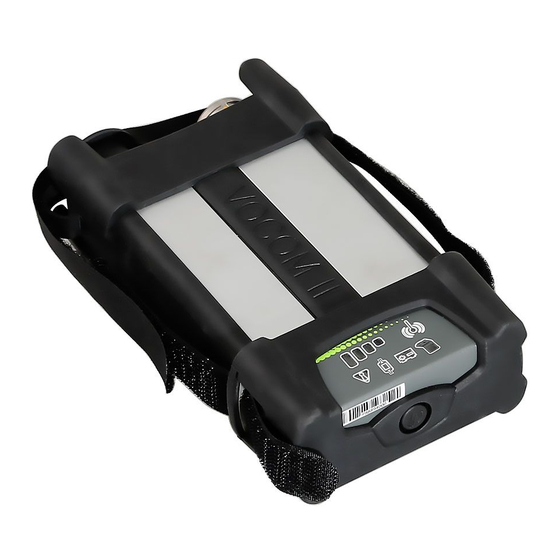
- Page 12 VOCOM II Operation Instructions Fig. 4–2: VOCOM II function indicators in WLAN operation mode WLAN connection PC link Vehicle power WLAN signal ECTA/OBD connector The information is developed by © Volvo Group in Sweden.
- Page 13 5 seconds to reset the device to factory defaults: Device name Paired client WLAN configuration Note: Resetting the device does not revert the firmware version. Fig. 4–3: Reset button of VOCOM II Reset button The information is developed by © Volvo Group in Sweden.
-
Page 14: Operation Modes
The vehicle battery status is indicated by the Vehcial power LED. 1. Normal battery state (12/24-V operation) is indicated by green colour. 2. Low battery states are indicated by yellow (low) and red colour (critical). The information is developed by © Volvo Group in Sweden. - Page 15 The vehicle battery status is indicated by the Vehicle power LED. 1. Normal battery state (12/24-V operation) is indicated by green colour. 2. Low battery states are indicated by yellow (low) and red colour (critical). The information is developed by © Volvo Group in Sweden.
-
Page 16: First Time Setup
Startup screen of the VOCOM II Windows installer If the device driver installation has been successfully completed, a task bar notification will be shown: Device ready to use Fig. 5–3: The information is developed by © Volvo Group in Sweden. - Page 17 When the firmware is finished, the device will reboot itself. Wait a couple of seconds to make sure that an FPGA update is not necessary. The following windows will pop up in case of an FPGA update. Automatic firmware updating Fig. 5–6: The information is developed by © Volvo Group in Sweden.
-
Page 18: Setup
WLANis used when connecting directly to the VOCOM II. This mode is typically used in the field. WLAN - Infrastructure is used when both the computer and the VOCOM II connect to the same network. This mode is most suitable for workshops. The information is developed by © Volvo Group in Sweden. - Page 19 Click Pair in the popup window. The VOCOM II is now paired to this computer. Click on the Configuration tab. Select the Connection type: WLAN - Access Point. Fig. 5–8: Connection Type WLAN - Access Point 10 Set your preferred Network Settings: The information is developed by © Volvo Group in Sweden.
- Page 20 The VOCOM II network from the example. 17 On Windows 10 and later Windows versions, the messages “Enter the PIN on the router label” can appear. In that case click “Connect using a security key instead”. The information is developed by © Volvo Group in Sweden.
- Page 21 18 You should now be able to see the VOCOM II in the configurator again. VOCOM II connected via WLAN - Access Point. Fig. 5–13: 19 You are now connected to the VOCOM II through WLAN - Access Point The information is developed by © Volvo Group in Sweden.
- Page 22 Insert a Client Name (for example the name of the computer) in the popup window. Click Pair in the pop-up window. The VOCOM II is now paired to this computer. Click on the Configuration tab. Select the Connection type: WLAN Infrastructure. The information is developed by © Volvo Group in Sweden.
- Page 23 User name: The user name used to connect to the network (ignore if greyed out). Password: The password used to connect to the network (ignore if greyed out) Fig. 5–16: Example of network settings 12 Click Save to save the settings. The information is developed by © Volvo Group in Sweden.
- Page 24 To install the EAP-TLS/PEAP certificate, follow these steps. Click on the three dots. Select the location of the certificate you want to install. Then press install. Fig. 5–18: How to install a certificate The information is developed by © Volvo Group in Sweden.
- Page 25 VOCOM II Operation Instructions The EAP-TLS/PEAP Certificate will now look something like this. Fig. 5–19: Example of how it can look with an installed certificate. The information is developed by © Volvo Group in Sweden.
-
Page 26: Update Firmware
VOCOM II. The recommendation is to immediately take action to update the firmware. If that is not possible, the pop-up reminder allows you to set a time for a new reminder. The information is developed by © Volvo Group in Sweden. -
Page 27: Configuration
Note: The Information tab is the default tab when opening the application or when selecting another device in the list. Note: The Device list is continuously updated and will update the connection type as they change or show new devices as they become available. The information is developed by © Volvo Group in Sweden. - Page 28 To save configuration changes and reboot the device, use the Save and Reboot buttons on the Menu bar. The Edit button opens the configuration page for basic device setup, factory reset and device pairing. The information is developed by © Volvo Group in Sweden.
- Page 29 Device list. Among those features is the Help function, the Language settings, the Log Configuration dialog and the Device mapping dialog. For more information see chapter 7.4 Options menu functions. The information is developed by © Volvo Group in Sweden.
-
Page 30: Device List
In the basic VOCOM II device setup you can do the following: Change the Device Name. Pair the device with the local PC. Reset the device configuration to factory settings. The information is developed by © Volvo Group in Sweden. - Page 31 Changing the Device Name Device Name Save button Click Reboot. The new Device Name is updated in the corresponding Device list entry and Information page. Fig. 7–5: Changing the Device Name The information is developed by © Volvo Group in Sweden.
- Page 32 To pair a VOCOM II device, perform the following steps: Click the Edit button in the Menu bar. In the Configuration page, click the Pair button. Fig. 7–6: Pairing a VOCOM II device with a client PC Pair button The information is developed by © Volvo Group in Sweden.
- Page 33 In the Pairing dialog, enter a name (Client Name) to be displayed in the Info bar. In the Pairing dialog, click on the Pair button. Note: The currently paired computer is always displayed in the Info bar in the Client ID field. The information is developed by © Volvo Group in Sweden.
- Page 34 VOCOM II Operation Instructions Fig. 7–8: Pairing a VOCOM II device with a client PC Client ID The information is developed by © Volvo Group in Sweden.
- Page 35 To perform a factory reset, perform the following steps: Click Edit from the Menu bar. In the Information page, click Factory Reset. Confirm the factory reset. Reboot the device. Fig. 7–9: Performing a factory reset Factory Reset button The information is developed by © Volvo Group in Sweden.
-
Page 36: Wlan Configuration
When WLAN connection has been successfully established, the WLAN signal strength is indicated by the 4 LED bars. WLAN RX/TX activity is indicated by flashing WLAN connection and PC Link indicators, if Vehicle traffic is on-going. The information is developed by © Volvo Group in Sweden. - Page 37 Password v2t[serial number] Example: v2t7100133 Encryption WPA + WPA2 Channel IPv4 address 192.168.51.1/24 Activate DHCP server IPv4 address range 192.168.51.101 - 192.168.51.149 WLAN – Access point default settings Tab. 7–1: The information is developed by © Volvo Group in Sweden.
- Page 38 Click Configuration from the Menu bar. Select WLAN - Access Point in the Connection Type panel. Change the VOCOM II Access Point settings according to your needs. Click Save. Click Reboot. The information is developed by © Volvo Group in Sweden.
- Page 39 VOCOM II Operation Instructions Fig. 7–11: Changing the WLAN - Access Point configuration Connection Type panel Network Name Password IPv4 Address IPv4 Address Range Save button Reboot button The information is developed by © Volvo Group in Sweden.
- Page 40 PC in LAN not using VOCOM II (Local Area Network) LAN Enterprise Wi-Fi router in the LAN Vehicle connected to VOCOM II Vehicle cable VOCOM II connected to Enterprise Wi- VOCOM II Fi Router The information is developed by © Volvo Group in Sweden.
- Page 41 User Name Password The default setting is WPA+WPA2/WPA-PSK for password-based authentication and encryption, which is normally used for small “personal” wireless networks. This WLAN Infrastructure mode is commonly called “WPA-Personal”. The information is developed by © Volvo Group in Sweden.
- Page 42 Radius server), click Install button. After successful upload and installation of a certificate on the VOCOM II, the currently installed client certificate will be listed in the Network Settings panel. The information is developed by © Volvo Group in Sweden.
- Page 43 VOCOM II Operation Instructions Fig. 7–14: WLAN - Infrastructure EAP-TLS configuration Configuration tab WLAN Configuration panel Authentication Certificate/Install button User Name Save button Reboot button The information is developed by © Volvo Group in Sweden.
- Page 44 PC. For the country-specific WLAN radio settings implemented in VOCOM II firmware see chapter 12.3 WLAN country settings. These radio settings cannot be changed by the user. The information is developed by © Volvo Group in Sweden.
- Page 45 To show the manual WLAN - Infrastructure settings, perform the following steps: Open the WLAN - Infrastructure configuration page. Select Advanced configuration in the WLAN Configuration panel. Fig. 7–16: WLAN - Infrastructure – Advanced Configuration Configuration tab WLAN Configuration panel The information is developed by © Volvo Group in Sweden.
- Page 46 Change the IPv4 and IPv6 address assignment according to your needs. Click Save. Click Reboot. Fig. 7–17: WLAN - Infrastructure configuration – static IPv4 address assignment Configuration tab WLAN Configuration panel The information is developed by © Volvo Group in Sweden.
- Page 47 By default VOCOM II performs scans for Access Points of a wireless network on both frequency bands. Note: Restricting the WLAN frequency band to either 2.4-GHz or 5-GHz will reduce the number of WLAN channels to be considered in background scanning. The information is developed by © Volvo Group in Sweden.
- Page 48 This configuration is used when IP multicasting is not supported in the network. Unicast mode enables the user to connect to a wireless network using unicasting. Fig. 7–18: Unicast setting where Host Identifier is an IP address The information is developed by © Volvo Group in Sweden.
- Page 49 Note: If the host identifier is a DNS name, it has to be a full qualified DNS name including the DNS suffix. For more information about Unicast infrastructure setup contact help desk. The information is developed by © Volvo Group in Sweden.
-
Page 50: Options Menu Functions
RP1210 and J2534 device mappings, log levels and help links. Fig. 7–20: Options menu location in VOCOM II Configurator Options menu button Fig. 7–21: Options menu Options menu The information is developed by © Volvo Group in Sweden. - Page 51 VocomConfiguration VOCOM II Config API Windows logs logging VocomLocate VOCOM II Locate API Windows logs logging VocomService VOCOM II Service logging Windows logs Tab. 7–5: VOCOM II log modules The information is developed by © Volvo Group in Sweden.
- Page 52 7.4.7 Download log files. VOCOM II Windows logs can be found under: C:\ProgramData\ACTIA I+ME GmbH\VOCOM II\Log. Note: Log levels will be reset to their default values by an installer update. The information is developed by © Volvo Group in Sweden.
- Page 53 In the Device column, select the VOCOM II serial number to be assigned to a particular Device ID. Click Save. Fig. 7–23: Mapping configuration page (defaults) Mapping columns Save button Note: The RP1210 Device ID mapping will be reset by an installer update. The information is developed by © Volvo Group in Sweden.
- Page 54 Perform the Device ID assignment for each of the two WLAN-connected devices. Click Save. Fig. 7–24: RP1210 Device ID mapping example for two WLAN-connected VOCOM II devices Options menu Mapping columns Save button The information is developed by © Volvo Group in Sweden.
- Page 55 Help and About menus At the bottom of the Options menu, you will find the Help and About items. Clicking the Help item will open and display the VOCOM II Tough Operation Instructions (this document). Clicking the About item displays version information for VOCOM II Configurator.
- Page 56 Change the name of the file to be stored (optional). Click the Download button to download Device Logs to specified location. Fig. 7–26: Download traces from VOCOM II Source of download Destination of download Filename Download button The information is developed by © Volvo Group in Sweden.
-
Page 57: Status Tab
Error List entry. Test tab The communication test can be found in the Test tab. Use this for a fast overview of what communication lines are opened to a connected vehicle. The information is developed by © Volvo Group in Sweden. -
Page 58: Operation
ID 2 in RP1210_ClientConnect, you connect to the first VOCOM II WLAN device found in the Device list. For workshops and applications with several wireless VOCOM II units, you have to manually set up the RP1210 device mapping in the VOCOM II Configurator. The information is developed by © Volvo Group in Sweden. -
Page 59: Usb Mode Operation
When connected via USB, the VOCOM II device is represented in the Windows Device Manager as network adapter named "VOCOM II Tough". For more information on function indicators for USB operation, see section 4.2.2. USB operation mode. The information is developed by © Volvo Group in Sweden. -
Page 60: Troubleshooting
WLAN. Note: If none of the above solves the problem, contact support with the logs for support cases. See section 7.4.7 Download log files. The information is developed by © Volvo Group in Sweden. -
Page 61: Vocom Ii Error Codes
0008 IEEE 802.1X Login credentials Make sure to use a valid were rejected by certificate or user name and authentication authentication server. password. failed The information is developed by © Volvo Group in Sweden. - Page 62 1100 Try the update again later. Update failed due The image contents to failed as written to the flash checksum check memory were found to be corrupted. The information is developed by © Volvo Group in Sweden.
- Page 63 Hardware fault: WLAN calibration The device must be replaced WLAN calibration data defect detected. data 9004 Hardware fault: Temperature sensor The device must be replaced temperature cannot be accessed. sensor The information is developed by © Volvo Group in Sweden.
- Page 64 9200 WLAN Self Test Connection to the Make sure that network unsuccessful network unsuccessful settings and credential match after time-out. the network you wish to connect to. The information is developed by © Volvo Group in Sweden.
- Page 65 LED status) 8011 Repower device and try again. PTApp crashed Abnormal end due to (certain LED crash Update to latest firmware. status) Tab. 9–2: Troubleshooting machine faults of VOCOM II The information is developed by © Volvo Group in Sweden.
-
Page 66: Maintenance
Repair works include the replacement of the complete VOCOM II device and are only required when components are damaged by wear or other external circumstances. Do not repair the VOCOM II device yourself. The information is developed by © Volvo Group in Sweden. -
Page 67: Disposal
Do not dispose VOCOM II with household waste. Bring the device to a specialist company for proper disposal. Observe the national and local regulations during disposal. Observe WEEE Directive 2012/19/EU. The information is developed by © Volvo Group in Sweden. -
Page 68: Technical Specifications
Knorr/Wabco ABS, NIRA EDC1, Volvo Penta MEFI, BOSCH EDC, J1708 DIS, Geartronic, SL2, Q/A, Free Running Smartcable SL2, Q/A, Free Running USB/Ethernet interface USB 2.0 with 480 Mbit/s USB/Ethernet communication via RNDIS interface The information is developed by © Volvo Group in Sweden. - Page 69 Connectivity CPU Qualcomm/Atheros AR9350 SoC Vehicle CPU SmartFusion2 SoC Memory 2 x 128-MB DDR RAM, 128 MB NAND FLASH, 16 MB NOR FLASH Tab. 11–1: Technical specifications of VOCOM II The information is developed by © Volvo Group in Sweden.
-
Page 70: Appendix
VOCOM II Operation Instructions Appendix Specifications Tab. 12–1 lists the product features of VOCOM II Tough. Parameter Description Supports 12 V or 24-V power supply Vehicle Power supply Operating voltage 6–32 V USB Power Supply USB 2.0 High-Power Device or USB 3.0 High-Power Device... -
Page 71: Vehicle Communication Interfaces
Low: 0–3.5 V, High: 7.2–32 V, TH: 4.25 V 3x DO High-side automotive switches, 200 mA RT legacy Via VOCOM II Smartcable Tab. 12–2: Vehicle communication interfaces of VOCOM II The information is developed by © Volvo Group in Sweden. -
Page 72: Wlan Country Settings
VOCOM II Operation Instructions WLAN country settings The information is developed by © Volvo Group in Sweden.
Need help?
Do you have a question about the VOCOM II Tough and is the answer not in the manual?
Questions and answers