Table of Contents
Advertisement
Advertisement
Table of Contents

Related Manuals for Volvo VOCOM II Tough

Summary of Contents for Volvo VOCOM II Tough
- Page 1 VOCOM II Operation Instructions VOCOM II Tough...
-
Page 2: Table Of Contents
Configuration Device list Perform basic device setup WLAN configuration Options menu functions Advanced menu functions Operation WLAN mode operation USB mode operation Troubleshooting General procedure VOCOM II error codes Maintenance The information is developed by © Volvo Group in Sweden. - Page 3 VOCOM II Operation Instructions Care and cleaning Checks and updates Repairs Decommission 10.1 Switch off VOCOM II 10.2 Recommission 10.3 Final decommission / disposal Technical specifications Appendix 12.1 WLAN country settings The information is developed by © Volvo Group in Sweden.
-
Page 4: Identification
Operation Instructions Identification The VOCOM II communication unit is the latest diagnostic hardware tool developed by Volvo Group for maintenance of trucks, buses, engines and machines. Three VOCOM II product variants exist for use in workshops (Tough variant), production lines (Tough and Light variant) and "on the truck"... - Page 5 VOCOM II Operation Instructions Tab. 1–1 lists the product features of VOCOM II Tough. Parameter Description Supports 12 V or 24 V power supply Vehicle Power supply Operating voltage 6 V to 32 V USB Power Supply USB 2.0 High Power Device or USB 3.0 High Power Device...
-
Page 6: About Vocom Ii Tough Operation Instructions
Chap. - Reference to a chapter Fig. - Reference to a figure NOTE Symbol for additional information and instructions. See Classification of the warning instructions. ( Chap. 3.1.2 "Classification of the warnings" The information is developed by © Volvo Group in Sweden. -
Page 7: Validity Of The Operation Instructions
Validity of the operation instructions These operation instructions are valid only for the following product: VOCOM II Tough, hereinafter referred to as "VOCOM II" or "device". The type of the device is specified on the type plate. Type plate The type plate is attached to the housing. -
Page 8: Warranty And Liability
Operation Instructions Warranty and liability VOCOM II comes with a 2 year warranty. Volvo Groups Spare Parts Warranty applies. Warranty and liability claims for personal and property damage are excluded if they are due to one or more of the following causes: ... -
Page 9: For Your Safety
Proper and intended use VOCOM II Tough is intended solely for maintaining trucks, buses, engines and machines made by Volvo Group. VOCOM II Tough is used for vehicle diagnostic communication in workshops, production facilities and warehouses. The information is developed by © Volvo Group in Sweden. -
Page 10: Warnings
Serious injuries due to improper maintenance work! Improperly performed maintenance work can impair the safety of the device and cause serious injuries. Only allow authorized and instructed personnel to perform maintenance work. The information is developed by © Volvo Group in Sweden. -
Page 11: Limits Of Use
Not authorized for EX areas in hazardous areas) Operation and Transport & storage: Humidity and temperature 75 % humidity at -40°C to +85°C (-40°F to +185°F) Tab. 3–1: Limits of use of VOCOM II The information is developed by © Volvo Group in Sweden. -
Page 12: Design And Function
6 ECTA-12 / USB connector with dust cap Communication interfaces 4.2.1 Vehicle communication interfaces Tab. 4–1 lists the available vehicle communication interfaces for VOCOM II: Vehicle Description communication interface 2 CAN channels Compliant to ISO 11898-2:2015 The information is developed by © Volvo Group in Sweden. - Page 13 The following symbols are located on the plastic cap of VOCOM II: Symbol Indicator name Description Vehicle power Multi-colour LED Green: normal Orange: too low/high Red: critically low/high PC Link Green LED Continuous: USB powered Flashing: PC Comm activity The information is developed by © Volvo Group in Sweden.
- Page 14 Blinking 1 Hz: WLAN link / scanning, not connected Continuous: WLAN link / connected Flashing: WLAN Comm activity Smartcable Green LED Connectivity Continuous: Smartcable connected Tab. 4–2: Function indicators of VOCOM II The information is developed by © Volvo Group in Sweden.
-
Page 15: Operation Modes
WPS button of VOCOM II 1 WPS button Operation modes VOCOM II is designed and constructed for use in the following operation modes: WLAN operation mode USB operation mode The information is developed by © Volvo Group in Sweden. - Page 16 The vehicle battery status is indicated by the VBAT status LED. Normal battery state (12/24 V operation) is indicated by green colour. Low battery states are indicated by yellow (low) and red colour (critical). The information is developed by © Volvo Group in Sweden.
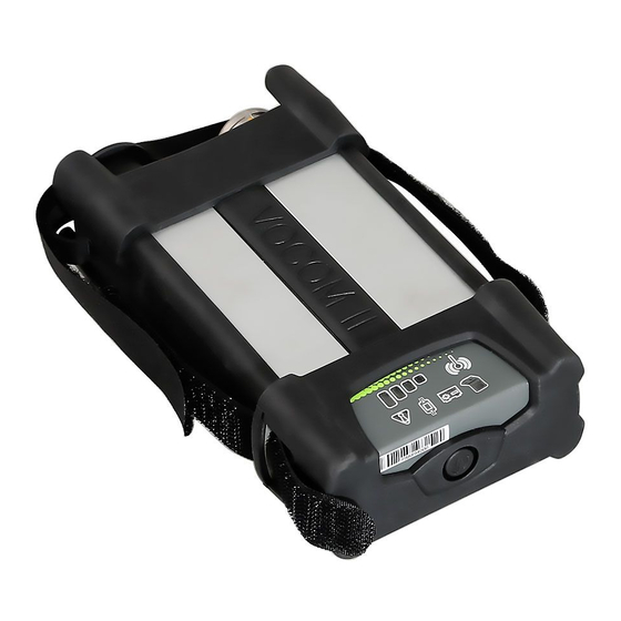
- Page 17 Fig. 4–4: VOCOM II function indicators in WLAN operation mode 1 WLAN connectivity status 4 WLAN signal strength 2 PC communication status 5 ECTA / OBD connector 3 VBAT status The information is developed by © Volvo Group in Sweden.
- Page 18 The vehicle battery status is indicated by the VBAT status LED. Normal battery state (12/24 V operation) is indicated by green colour. Low battery states are indicated by yellow (low) and red colour (critical). The information is developed by © Volvo Group in Sweden.
-
Page 19: Supported Vehicle Communication Apis
Supported vehicle communication APIs VOCOM II supports the following vehicle communication APIs: Smartphone API RP1210C API 2534/J2534-1 API VOCOM II supports several vehicle communication interfaces. (chap. 4.2.1 “Vehicle communication interfaces”) The information is developed by © Volvo Group in Sweden. -
Page 20: Installation
4 ECTA / OBD connector Connect the VOCOM II device to the USB port of the PC. The device is ready to communicate when the PC communication status LED shines green. The information is developed by © Volvo Group in Sweden. - Page 21 If for some reason the device driver fails to install, try again by disconnecting VOCOM II from the USB port and connecting it to a different USB port or by restarting the computer. The information is developed by © Volvo Group in Sweden.
-
Page 22: Firewall Rules
Port: 80 VOCOM II HTTP Direction: outbound Protocol: TCP Port: 27015 VOCOM II HTTP Direction: outbound Protocol: TCP Port: 2534 Tab.5–1: Firewall rules The information is developed by © Volvo Group in Sweden. -
Page 23: Configuration
This is the default tab when opening the application or when selecting another device in the list. NOTE The Device list is continuously updated and will update the connection type as they change or show new devices as they become available. The information is developed by © Volvo Group in Sweden. - Page 24 Menu bar at the top and the Configuration page in the middle right. The Info bar shows information about the software version and connection mode of the selected device. The Configuration page displays content from the currently active configuration page. The information is developed by © Volvo Group in Sweden.
- Page 25 Device list. Among those features are the Help function, the Language settings, the Logging configuration dialog and the Device mapping dialog. Chap. 6.4 "Options menu functions") The information is developed by © Volvo Group in Sweden.
-
Page 26: Device List
Change the Device Name and Sticker number. Pair the device with the local PC. Reset the device configuration to factory settings. Perform a firmware update. ( Chap. 6.2.46.2.4 “Perform Firmware Update The information is developed by © Volvo Group in Sweden. - Page 27 4 Click Reboot. The new Device Name and / or Sticker number are updated in the corresponding Device list entry and Information page. Fig. 6–5: Changing the Device Name and Sticker number The information is developed by © Volvo Group in Sweden.
- Page 28 Click on the Edit button in the Menu bar. 2 In the Configuration page, click on the Pair button. Fig. 6–6: Pairing a VOCOM II device with a client PC 1 Pair button The information is developed by © Volvo Group in Sweden.
- Page 29 3 In the Pairing dialog, enter a name (Client Name) to be displayed in the Info bar. 4 In the Pairing dialog, click on the Pair button. NOTE The current paired computer is always displayed in the Info bar in the Client ID field. The information is developed by © Volvo Group in Sweden.
- Page 30 VOCOM II Operation Instructions Fig. 6–8: Pairing a VOCOM II device with a client PC 1 Client ID The information is developed by © Volvo Group in Sweden.
- Page 31 1 Click Edit from the Menu bar. 2 In the Configuration page, click Factory Reset. 3 Confirm the factory reset. 4 Reboot the device. Fig. 6–9: Performing a factory reset 1 Factory Reset button The information is developed by © Volvo Group in Sweden.
- Page 32 NOTE If the new firmware version includes an FGPA update, the firmware update may continue after device reboot. NOTE Updating the internal FPGA on VOCOM II may take several minutes. The information is developed by © Volvo Group in Sweden.
-
Page 33: Wlan Configuration
When the WLAN connection has been successfully established, then the WLAN signal strength is indicated by the 4 LED bars. WLAN RX/TX activity is indicated by flashing WLAN- and PC-Comm status indicators in case of Vehicle traffic is on-going. The information is developed by © Volvo Group in Sweden. - Page 34 WPA + WPA2 Channel IPv4 address 192.168.51.1/24 Activate DHCP server IPv4 address range 192.168.51.101 - 192.168.51.149 Tab. 6–3: WLAN-Direct default settings Fig. 6–11 shows the WLAN-Direct configuration page with default settings. The information is developed by © Volvo Group in Sweden.
- Page 35 VOCOM II Operation Instructions Fig. 6–11: WLAN-Direct configuration page Connection Type panel Connection tab Save button Reboot button The information is developed by © Volvo Group in Sweden.
- Page 36 3 Change the VOCOM II Access Point settings according to your needs 4 Click Save. 5 Click Reboot. Fig. 6–12: Changing the WLAN-Direct configuration Connection Type panel IPv4 Address Range Network Name (SSID) Save button Password Reboot button IPv4 Address The information is developed by © Volvo Group in Sweden.
- Page 37 Network Name / SSID field of the WLAN Infrastructure Configuration panel. 2 From Encryption and Authentication menus select a combination of Encryption-methods and WLAN-Authentication methods which is supported by your network. 3 Click Save. 4 Click Reboot. The information is developed by © Volvo Group in Sweden.
- Page 38 “WPA Enterprise”. 6.3.2.1 Network Settings for WPA-PSK For WPA-Personal mode the following network parameter have to be set. Parameter Description Network name / SSID The name (SSID) of the network The information is developed by © Volvo Group in Sweden.
- Page 39 Radius server), click Certificate/Install button. After successful upload and installation of a certificate on the VOCOM II, the currently installed client certificate will be listed in the Network Settings panel. The information is developed by © Volvo Group in Sweden.
- Page 40 Operation Instructions Fig. 6-15: WLAN-Infrastructure EAP-TLS configuration 1 Connection tab 5 User Name 2 WLAN Configuration panel 6 Save button 3 Authentication 7 Reboot button 4 Certificate / Install button The information is developed by © Volvo Group in Sweden.
- Page 41 Fig. 6-16: WLAN-Infrastructure EAP-PEAP configuration 1 Connection tab 5 User Name 2 WLAN Configuration panel 6 Password 3 Authentication 7 Save button 4 Certificate / Install button 8 Reboot button The information is developed by © Volvo Group in Sweden.
- Page 42 PC. ( Chap. For the country-specific WLAN radio settings implemented in VOCOM II firmware. 12.1. "WLAN country settings".) These radio settings cannot be changed by the user. The information is developed by © Volvo Group in Sweden.
- Page 43 IPv4 and IPv6 address assignment WLAN roaming threshold Frequency band selection Setup of VOCOM II for Volvo Factory wireless operation To show the manual WLAN-Infrastructure settings, perform the following steps: 1 Open the WLAN-Infrastructure configuration page.
- Page 44 3 Change the IPv4 and IPv6 address assignment according to your needs. 4 Click Save. 5 Click Reboot. WLAN-Infrastructure configuration – static IPv4 address assignment Fig. 6–18: 1 Connection tab 2 WLAN Configuration panel The information is developed by © Volvo Group in Sweden.
- Page 45 By default VOCOM II performs scans for Access Points of a wireless network on both frequency bands. NOTE Restricting the WLAN frequency band to either 2.4 GHz or 5 GHz will reduce the number of WLAN channels to be considered in background scanning. The information is developed by © Volvo Group in Sweden.
- Page 46 IP multicasting is not supported in the network. Factory wireless enables to connect to wireless network using unicasting. Fig. 6–19: Factory Wireless setting where Host Identifier is an IP address The information is developed by © Volvo Group in Sweden.
- Page 47 If the host identifier is a DNS name, it has to be a full qualified DNS name including the DNS suffix. For more information about Factory Wireless infrastructure setup contact help desk. The information is developed by © Volvo Group in Sweden.
-
Page 48: Options Menu Functions
RP1210 and J2534 device mappings, log levels and help links. Fig. 6–21: Options menu location in VOCOM II Config Application 1 Options menu button Fig. 6–22: Options menu 1 Options menu The information is developed by © Volvo Group in Sweden. -
Page 49: Language Settings
VocomConfiguration VOCOM II Config API Windows logs logging VocomLocate VOCOM II Locate API Windows logs logging VocomService VOCOM II Service logging Windows logs Tab. 6–5: VOCOM II logging modules The information is developed by © Volvo Group in Sweden. - Page 50 To change the mapping of logical RP1210 Device IDs to VOCOM II devices, perform the following steps: Go to the Mapping configuration page found under the Options menu. 2 Assign one or more Device IDs to VOCOM II serial numbers. The information is developed by © Volvo Group in Sweden.
- Page 51 RP1210 Device ID 2 Map to first WLAN-connected VOCOM II from Device list. RP1210 Device IDs 3 to 8 Not mapped by default. Tab. 6–6: Default RP1210 Device ID mapping The information is developed by © Volvo Group in Sweden.
- Page 52 2 Perform the Device ID assignment for each of the two WLAN-connected devices. 3 Click Save. Fig. 6–25: RP1210 Device ID mapping example for two WLAN-connected VOCOM II devices 1 Options menu 3 Save button 2 Mapping columns The information is developed by © Volvo Group in Sweden.
- Page 53 Help and About menus At the bottom of the Options menu you will find the Help and About items. Clicking on the Help item will open and display the VOCOM II Tough Operation Instructions (this document). Clicking on the About item displays version information for VOCOM II Config Application...
-
Page 54: Advanced Menu Functions
Advanced menu options You can navigate to the respective page by clicking on the corresponding section. Fig. 6–27: Advanced menu 1 Advanced tab 3 Self Test 2 Download 4 Error Memory The information is developed by © Volvo Group in Sweden. - Page 55 4 Click Downloads device logs to specified location to download. Fig. 6–28: Download traces from VOCOM II 1 Source of download 3 Filename 2 Destination of download 4 Download button The information is developed by © Volvo Group in Sweden.
- Page 56 Fig. 6–29 - Fig. 6–30 show how to run the Self Test. Fig. 6–29: Execute VOCOM II Self Test 1 Self Test execute button Fig. 6–30: Self Test in progress window The information is developed by © Volvo Group in Sweden.
- Page 57 Fig. 6-31 shows the Self Test result page. The shown test result is failed due to missing test adapter. Fig. 6-31: Self Test result page 1 Self Test information 2 Test Result messages The information is developed by © Volvo Group in Sweden.
- Page 58 Error Memory page 1 Refresh button 3 Filter button 2 Delete button To display the extended description of an event, click on one of the down-arrows of an Error Memory entry. The information is developed by © Volvo Group in Sweden.
-
Page 59: Operation
ID 2 in RP1210_ClientConnect, you connect to the first VOCOM II WLAN device found in the Device list. For workshops and applications with several wireless VOCOM II units, you have to manually setup the RP1210 device mapping in VOCOM II Config Application. The information is developed by © Volvo Group in Sweden. -
Page 60: Usb Mode Operation
When connected via USB, the VOCOM II device is represented in the Windows Device Manager as network adapter named "VOCOM II Tough". Chap. 4.3.2 "USB operation mode”) Function indicators for USB operation ( The information is developed by © Volvo Group in Sweden. -
Page 61: Troubleshooting
User name and / or Make sure user name / identity error password for and / or password match those authentication were on the authentication server. rejected by authentication server. The information is developed by © Volvo Group in Sweden. - Page 62 1010 Voltage low The voltage is lower Check the vehicle battery. than it should be. The information is developed by © Volvo Group in Sweden.
- Page 63 Check network settings - is a address configured but no DHCP server available? DHCP address received after n tries. 9000 Hardware fault: Firmware flash defect The device must be replaced Flash #1 detected. The information is developed by © Volvo Group in Sweden.
- Page 64 Make sure that the Self Test communication. adapter is plugged. communication error Repeat test with same Self Test adapter and another unit. If other unit tests success- fully, get a replacement for erroneous one. The information is developed by © Volvo Group in Sweden.
- Page 65 LED status) 8011 PTApp crashed Abnormal end due to Re-power device and try again. (certain LED crash Update to latest firmware. status) Tab. 8–1: Troubleshooting machine faults of VOCOM II The information is developed by © Volvo Group in Sweden.
-
Page 66: Maintenance
Repair works include the replacement of the complete VOCOM II device and are only required when components are damaged by wear or other external circumstances. Do not repair the VOCOM II device yourself. The information is developed by © Volvo Group in Sweden. -
Page 67: Decommission
Do not dispose VOCOM II with household waste. Bring the device to a specialist company for proper disposal. Observe the national and local regulations during disposal. Observe WEEE Directive 2012/19/EU. The information is developed by © Volvo Group in Sweden. -
Page 68: Technical Specifications
Knorr/Wabco ABS, NIRA EDC1, Volvo Penta MEFI, BOSCH EDC, J1708 DIS, Geartronic, SL2, Q/A, Free Running Smartcable SL2, Q/A, Free Running USB / Ethernet interface USB 2.0 with 480 Mbit/s USB/Ethernet communication via RNDIS interface The information is developed by © Volvo Group in Sweden. - Page 69 Qualcomm / Atheros AR9350 SoC Vehicle CPU SmartFusion2 SoC Memory 2 x 128 MB DDR RAM, 128 MB NAND FLASH, 16 MB NOR FLASH Tab. 11–1: Technical specifications of VOCOM II The information is developed by © Volvo Group in Sweden.
-
Page 70: Appendix
VOCOM II Operation Instructions Appendix 12.1 WLAN country settings The information is developed by © Volvo Group in Sweden.
Need help?
Do you have a question about the VOCOM II Tough and is the answer not in the manual?
Questions and answers