
Subscribe to Our Youtube Channel
Related Manuals for Jumper T16


Summary of Contents for Jumper T16
- Page 1 16-Channel Digital Proportional R/C System 使用说明书 ATTENTION ● Please read this manual carefully before use. ● Please keep this manual in a safe place after reading. Digital Proportional R/C System...
- Page 2 The information contained in this manual is subject to change without notice. This T16 transmitter is suitable for all types of models of fixed wings, gliders, helicopters and multi-rotors. The model type can be selected according to the body used, and various mixing functions can be used.
- Page 3 Components...
-
Page 4: Table Of Contents
Table of Contents 1. Overview..........................3 1.1. Disclaimer ........................3 1.2. Legal status and copyright ..................3 2. installation..........................4 2.1. ready .......................... 5 2.2. Backup remote firmware .................... 7 2.3. Backup models and settings ..................8 2.4. Upgrade remote firmware using Companion software ..........10 2.5. -
Page 5: Overview
1. Overview JumperTX is a firmware that runs on the T16. Its main purpose is to support the receiver of more protocols, thus developing all the potential of the remote control. The core of the JumperTX firmware is based on the modified Er9x firmware system of the Turnigy/Flysky9xTM remote. -
Page 6: Installation
Select the Write Firmware option after booting and select the appropriate firmware upgrade. In BOOTLOADER mode, you can also use USB to connect to a computer. You can use your computer to access the T16 disk data. After plugging in the USB, the display is as follows. -
Page 7: Ready
If you are upgrading an older version of JumperTX firmware, it is highly recommended that you back up your remote's configuration file to make sure you don't lose any model or remote- control configuration. Windows driver installation. The T16 uses the STM32 Bootloader driver. Can be downloaded here: Https://zadig.akeo.ie/... - Page 8 Turn off the T16 and connect to the computer using the USB cable. Open the downloaded Zadig software (some systems need to run in administrator mode, you can use right click and select to run as administrator) Click Options and select List All Devices. (as shown below) Click on the drop-down list to select STM32 BOOTLOADER (as shown below) Click Install Driver.
-
Page 9: Backup Remote Firmware
Open the Companion software and set the remote control model to T16 in the setup menu. Turn off the remote control or enter BOOTLOADER mode, connect the computer with a USB cable. -
Page 10: Backup Models And Settings
After the backup is complete, you can see the backup file under the path you just selected. 2.3. Backup models and settings Open the Companion software and set the remote-control model to T16 in the setup menu. Put the remote control into BOOTLOADER mode and connect the computer with a USB cable. - Page 11 Click on the file and select Save As (as shown below) In the pop-up dialog box, you can choose where to save the backup file and the file name you want to save. Click Save to start the backup (as shown below)
-
Page 12: Upgrade Remote Firmware Using Companion Software
Note: Before disconnecting the USB connection, remember to eject the device and then disconnect it to prevent damage to the contents of the SD card file. 2.4. Upgrade remote firmware using Companion software Too be added, not currently supported 2.5. Companion Software Introduction Too be added, not currently supported 2.6. - Page 13 Switch Warning: This is a warning that the remote-control switch is not in the default position. (The default setting is that all switches default backwards to the end) Out of control protection is not set Warning: This is a warning that the remote control's runaway protection is not set.
- Page 14 Alarm Off Warning: A similar warning will appear if the sound mode of the Remote Control Settings page is set to Mute. SD card warning: This warning will appear if the version of the SD card file used does not match the firmware version. (Update the firmware and also need to update the SD card content)
-
Page 15: Main Interface
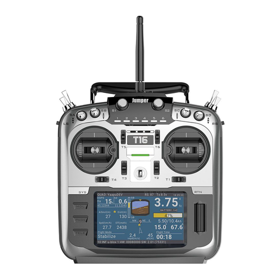
2.7. Main interface The default boot screen is as follows; the user can add the content to be displayed to customize the main interface. Top menu bar: The default top menu bar displays speaker volume, remote battery level, receiver signal strength (RSSI), and time and date. Users can also add other display information. - Page 16 Model Select: The Model Selection menu is used to create new, select to switch, delete and copy models. Monitors: Used to display the monitoring interface of channel output, mixed output and logic switch. You can use the page up button (PAGE) to switch other interfaces. The logic switch page can display the status of 64 logic switches.
- Page 17 Reset...: Used to call up various reset options. Reset flight: reset all timers and digital values (if there is an alarm when booting, it will reappear) Reset timer1, 2, 3: Reset a single timer. Reset telemetry: Reset the number of values.
- Page 18 Statistics: Show some statistics. This page displays flight statistics and throttle usage charts. Session: Current session time. Battery: Time since the last charge. Throttle, Throttle%: Throttle statistics, Throttle% set the time to run according to the throttle setting. The graph shows the value of the throttle channel as a function of time. Timers1, 2, 3: Timer statistics.
- Page 19 This page shows the raw data readings from the radio analog input device, with raw data on the left and -100 to 100 values on the right side of the analog input. The TELE key function is used to set user interface options, including top bar settings and main view screen layouts, which are very flexible due to the use of widgets.
- Page 20 Layout: There are 2 medium-sized widget areas on the left side of the default layout and 1 large area on the right side. The active layout is highlighted in white. There are 5 options, from 1 large area to 8 small areas. Press the ENT key to enter the edit mode (the icon changes from the currently selected white to red), then use the scroll wheel to select the layout option (or use the [TELE] and [SYS] buttons) to confirm the selection by pressing the ENT key.
- Page 21 to the widget settings page with the cursor on the first item in the selected category. Then you can scroll up/down from there and press ENT to select the source. Min, Max: The range allowed to be set. Color: Allows custom colors. Timer: Displays the timer value.
- Page 22 Press the PAGE key to enter the User Interface settings page. Theme: theme selection. Background color: Sets the RGB value of the background color. The default is R:248, G:252, B:248. Main color: Sets the RGB value of the foreground color. The default is R:224, G:32,:B:24. Top Bar: There are 4 small areas that can be used to add widgets to the Top Bar.
-
Page 23: System Settings
Press the ENT key to enter the setting and use the scroll wheel to select the part to be set. 2.8. System settings The System Setup menu is used to configure the remote hardware section and set global features for all models. RADIO SETUP: The remote control settings page is used to configure settings common to all models. - Page 24 NoKey: Beep, no sound when the button is pressed. Alarm: A beep will only sound when an alarm occurs, such as a battery voltage alarm. Quiet: Silent mode, no alarm sound will be emitted (set this mode, there will be an alarm off warning every time you turn it on) Volume: Master volume.
- Page 25 Inactivity: No action alarm for a long time. When set to 0, the alarm is turned off. Sound off: Check to turn off the sound. Check RSSI on Shutdown: Check to enable this alarm, which will be triggered if the remote is turned off without the aircraft being powered off.
-
Page 26: Sd Card
Units: The number of values will be displayed in metric or imperial depending on this setting (Metric Metric, Imperial Inch) FAI Mode: Disables all digital display except RSSI and RxBt to comply with the game regulations (requires Companion software check function). Play delay: This delay is the delay that does not report the midpoint of the switch when the midpoint of the 3-segment switch is reached. -
Page 27: Global Function
SxR: Frsky SxR series receiver setup script. THEMES: Remote control interface theme folder. WIDGETS: Some gadget scripts. 3.0. Global Functions The global functions GF1 to GF64 allow you to define standardized functions available for all modes, such as specific switches, potentiometers, sliders or settings, which avoids having to set the same function on each model, model-specific functions in "model settings (MODEL SETUP) ) in the "SPECIAL FUNCTIONS"... - Page 28 Use the scroll wheel to select up and down, then press the ENT key to confirm, then select the source to be set and press the ENT key to confirm (the front with the "!" symbol is reversed, such as SA and !SA, where !SA is the reverse SA) Next select the function in the list of available functions (some features have a second parameter setting available) !1X: Play this function once (do not play when booting)
-
Page 29: Trainer Mode
Trainer 3.1. This page is used to configure the master remote control settings for the coach mode, which are activated by setting the Trainer Mode to Master in the MODEL SETUP page. The mode can be set for 4 basic channels. OFF: Channels that do not use the coach mode. - Page 30 Set an enable switch, such as SA on the graph (the arrow represents the enabled switch position) Select Trainer and set the parameter to "---". Finally check to enable this feature. Add the following settings to the slave. In the Model Setup page, set the Trainer Mode to Slave / Jack. Turn off the internal and external tuner modules.
-
Page 31: Hardware
Then the slave will center the joystick, select Cal and press the ENT key to calibrate the input. After calibration, the 4 values should be close to 0.0. 3.2. Hardware This page lists the hardware physical input device types. A short three-character name can be given for identification on the setup page. -
Page 32: Version Information
Sticks: 4 basic channel control joysticks. Pots: S1, 6P, S2, they can be configured to: None Multipos Switch Pot with detent Max Bauds: The maximum baud rate of the external module can be switched between 115200 and 400000. Bluetooth: Can be set to Bluetooth Telemetry or Bluetooth Trainer mode, the default is off. - Page 33 Boot the main interface Long press the ENT key to select the Model Select menu, then press the ENT key (as shown below) Long press the ENT key to open the new model and other management menus (as shown below)
- Page 34 Select Rename category and press ENT to modify the category name (as shown below) To edit the category name, use the scroll wheel to select alphanumeric characters and characters, press the ENT key to select, while the cursor is selected to move to the next letter, long press the ENT key to switch between upper and lower case, short press the SYS button to move the cursor to the left, short press TELE Move the cursor to the right and press RTN to exit the edit mode.
-
Page 35: Model Setting
Use the scroll wheel to select the model you want to use, long press the ENT key to select Select model to switch the model. 3.5. Model Setup The model settings cover all the initial settings required. The Model Setup Model Setup page contains the following features: 1. - Page 36 9. Enable throttle adjustment for idle only. 10. Set up pre-flight inspection. 11. Set the display checklist. 12. Enable the center beep on the selected control. 13. Set up the internal RF module. 14. Set up the external RF module. 15.
- Page 37 Timers: There are 3 timers that can be set to count up or down. If set to 00:00:00, they will start from 0, otherwise they will count down. Source: Set how to trigger the timer. When set to ON, it will always count. When set to THs, the throttle will start timing.
- Page 38 Throttle Reverse: Check to reverse the throttle. Throttle Source: Defines the joystick that triggers the THx option, typically set to throttle. Throttle Trim Idle Only: IC engine mode. Preflight Checks: A set of security features that take effect when the remote is powered on or when the model is loaded from the model list.
- Page 39 D16: For the current 16ch bidirectional full duplex transmission, also known as X mode. For X series receivers. D8: Applies to the older 8ch bidirectional mode. LR12: Applicable to the current 12ch one-way long distance. Channel Range: Set the channel range. (D16 mode sends data every 9ms, 8 channels at a time, 16 channels need to send once every 18ms, so removing unnecessary channels can reduce the delay) Receiver No.: Only for the D16/LR12 protocol.
- Page 40 Failsafe Mode: Out of control protection settings. (D16/LR12 protocol only) Hold: Holds the last output value. (For example, 50% throttle is out of control, the receiving opportunity keeps 50% throttle until the signal is restored) Custom: Customize the runaway protection receiver output value. Select Set to enter the runaway protection custom settings page, and you can set the runaway protection value separately for each channel.
- Page 41 Note: You must carefully test the selected runaway protection settings for proper operation before taking off. Antenna selection: Allows selection of two internal antennas or an external antenna and reminds you to ensure that an external external antenna is connected when this option is selected.
-
Page 42: Helicopter Setup
Bind on powerup: The remote control is switched on when the power is turned on, and some protocols are optional. Low power mode: Some protocol optional features. R9M: Frsky 900MHZ tuner module. RF Power: Set the R9M module transmit power. SBUS: Turn on the external tuner SBUS output. -
Page 43: Flight Modes
The output of the CCPM mixer is CYC1, CYC2 and CYC3, and the servo channel needs to be assigned on the MIXER page. Swash Type: Swashplate type selection (90, 120.120X, 140). 120X means that cyc1 is rotated by 90 degrees. Swash Ring: The value is 0-100. - Page 44 There are 8 flight modes plus the default FM0 available. The first switch of FM1-8 is valid. When no switch is turned on, the default FM0 is valid. This explains why FM0 has no switches. Name: Each flight mode can have a 10-character name. Switch: Each flight mode has an optional activation switch (physical or logical) Trim selection array: Fine-tuning arrays have the following features.
-
Page 45: Input
Inputs->Mixer->Outputs: This is the top 3 pages of the remote control. Because JumperTX is very flexible and powerful, there is no standard mixing settings, and there are many ways to set the same effect. For this reason, the best practice is to describe the actual operation directly, so that you can develop a logic and a consistent way to write all the models. - Page 46 It is highly recommended to always create a last line that is not restricted by the switch or flight mode. This is to ensure that even if an invalid logic or switch failure invalidates other lines, at least the line will still be active, thus avoiding this.
- Page 47 Input name: Use the scroll wheel to select letters or numbers, long press the ENT key to switch between upper and lower case, short press the ENT key to switch to the next character. Line name: Because there can be multiple lines of configuration input, naming each line provides a label indicating the purpose of the line to avoid confusion.
- Page 48 (SrcValue x weight)+Offset =Result (100 x -50/100)+50=0 (0 x -50/100)+50=50 (-100 x -50/100)+50=100 Curve: Diff: The differential (usually down the aileron stroke) is used to reduce unfavorable yaw and improve cornering/maneuvering characteristics. (Default = 0, range -100 to +100). Although available here, it is best to set it on the mixing page.
-
Page 49: Mixer
Switch: The switch position (physical or logical) can enable/disable this input line. The Side: Side parameter limits the effect of the line to only one side of the source: --- (enabled within the full source range) x>0 (enabled only when source > 0) x<0 (enabled only when source >... - Page 50 Note that each row that is currently active and contributes to the channel output will display its source in bold. This is useful for debugging when many lines are set on the channel and the switch function is checked. Use the scroll wheel to select the mix list, press and hold the ENT key to enter the edit submenu.
- Page 51 Mix name: Use the scroll wheel to select letters and numbers, long press the ENT key to switch between upper and lower case. Short press the ENT key to set the next character. Source: Long press the ENT key to open the submenu for selecting the input source by category.
- Page 52 Curve: Diff: The differential (usually lower than the aileron stroke) is used to reduce unfavorable yaw and improve steering/maneuvering characteristics. (Default = 0, range - 100 to +100) Although Diff can also be used in input, it is usually used in mixing. Expo: The default curve is Expo, which by default is 0, which means that the response is linear (ie no curve) positive values make the response weaker around 0, while negative values make the response sharper.
-
Page 53: Outputs
Multpx: The Multpx setting defines how the current mixline interacts with other mixlines on the same channel. Add: Add to output. Multiply: Multiplies the results. Replace: Replace. The combination of these operations allows for the creation of complex mathematical operations and is often considered one of the biggest benefits of using JumperTX. -
Page 54: Curves
Min and Max limits: These are "hard" limits, ie. They will never be covered. Note that they are used as gain or “end point” settings, which can be extended to +/- 150% by checking the “Extended limits” option on the “Model Setup” page. For multi-rotor and helicopter flight controllers, the minimum and maximum limits must usually be adjusted to match your remote control travel to the expected flight controller travel. - Page 55 The curve can be between 2 and 17 points and can have a fixed or user definable x coordinate. The X value represents the input and the Y value represents the output. Name: For convenience, you can name the curve. Type: Standard: Only Y points can be edited, ranging from -100 to 100.
-
Page 56: Global Variables
Press and hold the ENT key on the coordinate point to enter the submenu: Preset: Allows selection of standard preset linear curves with slopes of -45, -33, -22, -11, 0, 11, 22, 33, 45. These can also be used as a starting point for more complex curves. Mirror: The curve will be mirrored vertically. - Page 57 Name: Set the name. Unit: For reference only, switch between normal and %. Precision: When switching to "0.0", the Gvar value is divided by 10 for the logic switch. This is necessary because, for example, Thr: -100 to 100 and GVars: -1024 to 1024.
-
Page 58: Logical Switches
4.3. Logical Switches The logic switch is a user-programmed virtual switch. They are not physical switches that flip from one location to another, but they can be used as program triggers just like any physical switch. By evaluating the input conditions for the programming of the logic switches, they are turned on and off (logically they become true or false). - Page 59 a<x: If the value of the selected source "a" (V1) is less than "x" (V2), the condition is True, which is the programmed value. |a|>x: If the absolute value of the selected source "a" (V1) is greater than "x" (V2), the programmed value, the condition is True.
-
Page 60: Special Functions
|d|>x: If the absolute value of "| d |" is changed, the condition is True in the selected source (V1), greater than "x" (V2), a programmed value. (Absolutely means to ignore whether a is positive or negative.) Timer: The logic switch is turned on and off continuously. It turns on time (V1) and turns off time (V2). - Page 61 Reset the telemetry value. Adjust global variables - Allows neat features, such as optimizing settings in flight. Adjust the volume. Play sounds, tracks, background music and/or vibration (tactile) feedback. Run the Lua script. Adjust the screen backlight. Save the screenshot to the SD card. Control data logging.
- Page 62 Then you can scroll up/down from there and press ENT to select the source. Function: The following functions are triggered by the switch selected above. Override: Forces the selected channel output (CH1 to CH32) to be a specific value between -100 and +100. This check box enables or disables this line. Caution: This function does not consider the minimum/maximum value and direction specified in the output menu, so the servo may be overdriven.
- Page 63 Checkbox: Enable/disable this line. Set: Time1, 2, 3: This function will preset the selected timer (00:00:00). Check the box to enable or disable this line. Adjust: Allows adjustment of global variables (GV1 to GV9). There are four options for "---": Value (between -500 and +500) Source (normal control range) GVAR, another global variable...
- Page 64 Pressing the ENT key while the mixing source is active will display the submenu of the source by category. Scroll up/down to the desired category and press the ENT key. It takes you back to the parameter being edited on the first item in the selected category. Then you can scroll up/down from there and press ENT to select the source.
-
Page 65: Custom Scripts
Select "---" and press and hold the ENT key to pop up the menu showing the source by category. Scroll up/down to the desired category and press ENT, which takes you back to the special features page with the cursor on the first item in the selected category. Then you can scroll up/down from there and press ENT to select the source. - Page 66 Various applications for web applications and image processing, in this case for implementing custom functions in the radio. There are three basic types: One-time: The script only runs once and then terminates. For example, the receiver and flight controller setup scripts, as well as the new Create Model Wizard. They are executed from the /SCRIPTS/folder on the SD card.
-
Page 67: Telemetry
You can select a script in the first line and optionally define a custom name to know what to use in the second line. The screen also displays the inputs and outputs used by the script. Basic layout of Lua scripts The user-written lua script is basically a subroutine called by the main loop of the remote control code. - Page 68 sensor type: RSSI Receiver Signal Strength Indicator (RSSI): The value transmitted by the receiver in the model to the remote control, indicating the strength of the received signal. Warnings can be set to warn below the minimum value, indicating that you are out of range. Factors affecting signal quality include external interference, excessive distance, poor orientation, or antenna damage.
- Page 69 All found sensors are automatically displayed during the discovery process. If no S.port sensor is plugged into the receiver, only the sensor that comes with the receiver can be found and set. Add a new sensor: Allows you to manually add new sensors. Short press the ENT key to call up the Add New Sensor menu.
- Page 70 If Ratio is "-", the telemetry value is calculated as follows: (sensing value divided by 10) (received value/10) + Offset=displayed value Or, if Ratio is not "-", the telemetry value is calculated as follows: [(received value / 255) * Ratio] + Offset = displayed value The ratio allows the received sensor values to be corrected or converted, for example between km / h or between sections.
- Page 71 The Lipo voltage sensor FLVSS adds the following parameters to the list: Cels: Total battery voltage. In order to get a single battery voltage, a new calculation sensor needs to be defined. Name: Cmin or Cmax. Type: Calculated Formula:Cell Cell sensor: Select from active Lipo voltage sensors, for example, Cels. Cell Index: lowest, 1, 2, 3, 4, 5, 6, highest.
- Page 72 Sensor: Curr Unit: mAh Persistent: When selected, this value will remain during power down and resume during power up. Logs: If checked, will be logged to the SD card. Please note that the record must still be started by the Special Function. Variometer settings: The vario sensor adds the Vspd and Alt parameters to the sensor list.
-
Page 73: Delta Wing
4.7. Simple delta wing setup example 1. First set the channel order (shown as AETR): 2. Create a blank new model:... - Page 74 Select New Model and press the RTN button to exit the wizard in the New Model Wizard interface that pops up. 3. Model settings: The Model Settings section contains all the initial settings required for input, mixing, output, and more. Model name: Enter your model name.
- Page 75 4. Determine the required servo/channel: With 32 output channels available, you can assign channels completely freely. Normally, the channel with the lowest number will be assigned to the servo because the channel number maps directly to the channel in the receiver. CH1: Lifting left.
- Page 76 Move the cursor to Ail, long press ENT to enter the edit pop-up window, then select the Edit option and press ENT. We use the 15% Expo curve to moderate the response around the neutral point (this can be adjusted to your liking). You can insert a new input line by moving the cursor to the input to which you want to add a line, then long press the ENT key to bring up the edit menu.
- Page 77 Only one input line is active at a time. If the switch SA fails, the last line will become True, which may not be the case if the Aile Hi and Elev Hi switch positions are set to SA↓. 7. Determine the interaction between the input and the channel: For example, CH1 moves up and down.
- Page 78 9. Configure the output: The next step is to adapt the pure logic output of the mixing phase to the mechanical properties of the model. Here you can configure the minimum and maximum stroke outputs, channel inversion, and adjust the servo center point using PPM center adjustment, or add offset using subtrim. Introduction to global variables: We can also use global variables to set the value of delta wing mixing.
- Page 80 Add a voice prompt: You can set the prompt voice for the switch to play when the switch is in the set position. Global features: Global features can be used to set standardized features that can be used by all models. The following example will define a global function, using the left slider LS as the volume control, which eliminates the need to enter the "Radio Setup"...
- Page 81 The ESC expects a complete control signal range of -100 to +100, so the Weight and Offset of the Thr input can be left at the default value. Press RTN to return (input) the Inputs page 2. Configure the Mixing (MIXER) page:...
- Page 82 Go to the Mixer page, scroll down to CH3 and press ENT to assign Thr to CH3. The Mixer page should be displayed as shown below. 3. Configure the Outputs page: Unable to provide accurate settings because the settings depend on the actual characteristics of your model...
- Page 83 4. Set the throttle lock function: The throttle lock function can be set to a switch to cut off the throttle passage to prevent misoperation. A logical unlock switch can be set to unlock when the unlock condition is met.
- Page 84 If the throttle stick is very close to -100 and the switch SD is in the "up position", then L01 becomes true, and if the lift stick is very close to -100 and the logic switch L01 is true, then L02 becomes true. If L02 remains true for at least 2 seconds, L03 is locked ON, and L03 is reset when the SD switch is dialed up.
Need help?
Do you have a question about the T16 and is the answer not in the manual?
Questions and answers