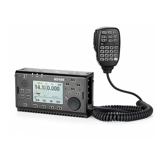
XIEGU X5105 Operation Manual
Hf/50mhz portable short-wave transceiver
Hide thumbs
Also See for X5105:
- Instruction manual (31 pages) ,
- Operation manual (23 pages) ,
- Manual (21 pages)

Related Manuals for XIEGU X5105


Summary of Contents for XIEGU X5105
- Page 1 XIEGU HF/50MHZ Portable Short-wave Transceiver X5105 Operation Manual V3.0 Preview Edition...
-
Page 2: Table Of Contents
Menu operation Attached items Panel keys Schematic diagram of connection between existing Multi-function menu models of Xiegu and XPA125/125B Transceiver start and shutdown Schematic diagram of CE-19 expansion card interface Battery level/voltage indication Selection of working frequency range Selection of working mode (MODE) -
Page 3: Basic Characteristics
CW, PSK, RTTY automatic decoding/preset message transmitting Built-in high-stability TCXO Manual/auto telegram key mode switch Wide working voltage range Please read this manual carefully for a better experience and full understanding on operation of the X5105. -
Page 4: Panel Keys
Panel Keys DATA LINK X5105 < MODE LOCK MENU... - Page 5 Panel Keys 1 Power switch 12 Major knobs (large thumbwheel) Major tuning knobs of radio can not only be used to adjust Press the key in a long time to turn on or turn off the radio. frequency, but also can be used to set parameters. 2 MODE key 13 ATU key Press the key in a short time to change current working mode and...
- Page 6 Panel Keys 21 Volume- key Press the key in a short time to reduce current volume. 22 Volume+ key Press the key in a short time to increase current volume. 23 PTT key The radio will enter transmitting state by pressing and holding the key. A T/R indicator light It is green when under receiving state It is red under transmitting state...
-
Page 7: Left Interface
It is a 3.5mm stereo socket (3 wires) interface used to connect earphone devices. * It shall be noted that functions of the interface will be different as for different version of X5105. 28 DC power interface It is an external DC power input interface used to connect external DC power by using attached power lines. -
Page 8: Right Interface
Right Interface 29 ACC interface The interface is an 8-core mini-type DIN interface which can be used for external amplifier connection, PTT control and band signal transmission, and it can be used to input/output acoustic signal under data communication state. 30 KEY interface It is a 3.5mm stereo interface used to connect manual/auto... -
Page 9: Handheld Microphone Function
Handheld Microphone Function Lock key 1. LOCK key transmitting control key 2. PTT key Frequency increase/decrease key 3. Up/down 4. Transceiver Hand microphone operation indicator indicator light light Figure keyboard area 5. Figure key area Filter selection 6. FIL key Selection of working mode of main 7. -
Page 10: Description For External Interfaces
Description for External Interfaces 1、 Microphone interface 4、 ACC interface MICE DATA MSVSW AF_OUT AF_IN MDATA BAND 5、Wire connection of telegram keys 2、 CIV interface Public Public 3、 Earphone interface Signal Signal... -
Page 11: Charging And Maintenance Of Build-In Battery
Charging and Maintenance of Build-in Battery X5105 has a built-in 3800mAh polymer lithium battery pack. When there is no external power supply connected, the battery pack will supply power for the whole device. When external power supply is provided, the built-in circuit will be automatically switched to the external power supply. - Page 12 Charging and Maintenance of Build-in Battery ○ When battery is supplying power and almost running out, the power indicator at top right corner of screen will display indicating that charging shall be carried out immediately or switching to external power supply is required. It will be normal if the shell is slightly exothermic when charging.
-
Page 13: Connection Of External Power Supplies
Connection of External Power Supplies 13.8V external DC power supply is available for X5105. Current load capacity of DC power supply shall be 3A at least. Attached power lines can be used to connect to radio and DC power supply. - Page 14 EMC magnet ring can be applied on power lines to prevent external disturbance from entering radio via power lines and radio- frequency interference in radio from radiating externally via power lines when external power supply is adopted for X5105. Magnet ring shall be installed at the side closing to battery socket.
-
Page 15: Menu Operation
Operation X5105 adopts multi-function menu mode to enable or disable various functions. All functions are distributed in 9 menu pages, and each page of menu has four functions that can be selected. Menu can be switched in following methods: Press MENU key in a short time to switch menu pages. -
Page 16: Panel Keys
Operation Description for functions of keys on panel Operation Name of keys Short press Long press Depend on PTT mode settings (assume that current frequency band is allowed to be transmitted): Normal PTT mode: press to enter transmitting state and loose to enter receiving state PTT triggering mode: switch between receiving and transmitting after every press Increase volume (a large Continuous increase of receiving volume until... - Page 17 Operation RIT selected/not RIT value zeroing (no matter whether selected RIT is selected or not) Cycle write current MEMO parameters in VFO Switch VFO/MEMO and return to VFO mode if under MEMO mode mode Cycle VFO mode: move frequency stepping Execute short press operation continuously position to left <...
-
Page 18: Multi-Function Menu
Operation Functions of each page in multi-function menu are distributed as follows: Menu page Functions RF-GAIN COMP Receiving radio frequency gain adjustment Voice compression Squelch AGC speed selection DSP-FLT NOTCH Digital noise reduction options DSP options NOTCH options EQ options MEMO CALLSIGN Storage options... - Page 19 Operation Menu page: 1 1 (common functions) Key labels RF-GAIN COMP Functions Select radio frequency Select noise threshold gains. SLOW Flickering when Flickering when selected Short press FAST Cycle selected Rotate thumbwheel to AUTO Rotate thumbwheel to adjust parameters adjust parameters Cycle Long press Restore defaults...
- Page 20 Operation 1-4 submenu Key labels COMP LEVEL Functions Select compression ratio Flickering when Short press selected Cycle Rotate thumbwheel to adjust parameters Long press Restore defaults...
- Page 21 Operation Menu page: 2 2 (DSP related) Key labels DSP-FIL NOTCH Functions Short press Cycle Cycle Cycle Cycle Long press Enter 2-2 submenu Enter 2-4 submenu Enter 2-1 submenu Enter 2-3 submenu Description of key functions: DSP-FIL: Digital filter function settings NR:...
- Page 22 Operation #2 submenu list 2-1 (parameter adjustment of band-pass filter) Key labels DSP-FIL L-CUT H-CUT Functions Select filter high. Select filter low. Flickering when Flickering when selected, selected, Short press Rotate thumbwheel to Rotate thumbwheel to Cycle adjust adjust Parameters Parameters Long press Return to 2 main menu...
- Page 23 Operation #2-3 (NOTCH parameter adjustment) Key labels NOTCH Functions Notch selected/not Notch selected/not selected selected Bandwidth Frequency point Flickering when Flickering when Short press Cycle selected selected Rotate thumbwheel to Rotate thumbwheel to adjust adjust Parameters Parameters Long press Return to 2 main menu Default Default #2-4 (EQ parameter adjustment)
- Page 24 Operation Menu page: 3 3 (memorizer related) Key labels MEMO CALLSIGN Functions Short press Enter 3-1 submenu Enter 3-2 submenu Enter 3-3 submenu Long press Description of key functions: MEMO: Storage channel settings MSG: Preset message list editing CALLSIGN: Boot screen call number editing...
- Page 25 Operation #3 submenu list #3-1 (channel manager) Key labels BACK SAVE Functions When CH is selected: Select CH Save and exit Insert a letter to Deletion line will be TAG. It is only Select TAG displayed above valid when TAG is channel contents after Cycle selected...
- Page 26 Operation #3-2-1 (list of preset messages) Key labels EDIT Functions Delete currently Edit currently selected Exit selected preset preset messages. messages. Confirmation prompt: Short press YES: confirm deletion NO: abort deletion Long press #3-2-2 (preset messages list editor) Key labels BACK SAVE Functions...
- Page 27 Operation #3-3 (call number editor) Key labels SPACE BACK SAVE Functions Delete a character at Insert currently selected Insert a space at the Save and exit Short press the position where characters at the position position where cursor cursor is where cursor is Long press Note: press MENU key in a short time to abort changes and return to 3 main menu.
- Page 28 Operation Menu page: 4 4 (telegram keys/CW related) Key labels TONE QSKTIME Functions Select CW sidetone. Select QSK delay. Manual key Flickering when Flickering when selected, selected, Auto key-left hand Short press Rotate thumbwheel to Rotate thumbwheel Auto key-right hand Cycle adjust to adjust...
- Page 29 Operation Menu page: 5 5 (special functions) Key labels DIGI Functions Start standing- Start scanning Short press Enable data mode wave scanner receiver Long press #5 submenu list #5-2 (data mode) Key labels PSK31 Functions Select data mode Selected/not Select preset massages Selected/not selected selected Carrier frequency...
- Page 30 Operation #5-3 (scanning receiver) Key labels QUIT STOP Functions Switch scanning Pause/ (Monitoring current step frequency point) Short press Exit 0.5/1/2/5/10kHz recover scanning Cycle Cycle Long press...
- Page 31 Operation #5-4 (standing-wave scanner) Key labels QUIT MODE SPEED Functions Exit Switch scanning Switch scanning Switch scanning mode speed step 1/5/10kHz Single step/continuous Short press Fast/slow Cycle Cycle Cycle Long press Clarifications: MODE: Single step: stop after every round of scanning, and then press PTT key (onboard or Hand microphone PTT) to trigger next scanning ...
- Page 32 Operation Menu page: 6 6 (interface functions) Key labels MIC/VOX LIN/OUT Functions Built-in loudspeaker/ PTT conventional/ Auto/built-in/external Enter 6-3 submenu external triggering mode Short press Cycle Earphone Cycle Cycle Long press Enter 6-1 submenu Clarifications: MIC: AUTO: built-in microphone will be automatically selected when hand microphone is not detected, otherwise external microphone will be selected.
- Page 33 Operation #6 submenu list #6-1 (MIC gain adjustment) Key labels G-VOX GAIN-IN GAIN-EX Functions Select built-in MIC Select external MIC Select built-in VOX On/Off gains and rotate gains and rotate gains and rotate Short press thumbwheel to achieve thumbwheel to achieve thumbwheel to achieve Cycle the adjustment...
- Page 34 Default Clarifications: X5105 hardware without screen protection plate has no individual LINE OUT channel. Its LINE OUT shares the same signal with audio frequency amplifier. At this time, LINE OUT/switch and LINE OUT gain have no effect, and the LINE OUT terminal of ACC interface is outputting all the time with output level related to receiving volume.
-
Page 35: Transceiver Start And Shutdown
Operation Routine operation Transceiver start and shutdown 1. Start the transceiver: press and hold the Switch key switch key for 1s. X5105 DATA LINK 2.Shut down the transceiver: press and hold < the switch key for 1s under startup state. -
Page 36: Battery Level/Voltage Indication
Press NB key to switch the battery level/voltage indication. If the X5105 transceiver is not used for more than 30 days, we suggest to connect it with an external power supply to charge it until the charging is finished. See operation instructions in [Charging] for details. -
Page 37: Selection Of Working Frequency Range
Operation Selection of working frequency range Frequency range of X5105 covers 0.5~54MHz. Amateur frequency in such range is divided into several frequency bands, and frequency band switch can be HF+50MHz TRANSCEIVER achieved by adopting many types of different modes. Frequency band downward... -
Page 38: Selection Of Working Mode (Mode)
Operation Operating mode selection Press [MODE] key and follow the fixed sequence below among all modes DATA LINK X5105 < Mode MODE LOCK MENU... -
Page 39: Volume Adjustment
Operation Volume adjustment Press [volume+, -] key to adjust the output volume HF+50MHz TRANSCEIVER Volume + Volume - Tips: Press volume+ or - key in a long time to continuously increase or decrease volume until loosening the key. -
Page 40: Adjustment Of Transmitting Power (Po)
Po power setting value. 2. Rotate large knob to set power within the range of 0.1W-5W. Please minimize the preset transmitting power when using X5105 transceiver for the first time under the condition of not understanding the current state of antenna. -
Page 41: Use Of Ptt Key Of The Device
Operation Use of PTT key of the device X5105 has a build-in PTT key which can enable the transmission of transceiver. Operation methods: 1. Press the key to enable the HF+50MHz TRANSCEIVER transmitting function of transceiver; PIT of the 2. Speak to the built-in MIC hole beside... -
Page 42: Working Frequency Settings
2. Set frequency by using multi-function hand microphone Press [F-INP ENT] key on hand microphone, and the X5105 will be in frequency setting state, and cursor will be flickering at the first place on the ... -
Page 43: Automatic Antenna Tuner (Atu)
Operation X5105 DATA LINK There is an efficient ATU < integrated inside X5105 transceiver to help you easily erect MODE and debug antenna. Tuning key LOCK Press [ATU] key in a short time MENU to connect with built-in antenna tuner. -
Page 44: Fine Tuning Of Received Frequency (Rit)
Operation Fine tuning of received frequency (RIT) RIT function can set the deviation X5105 value actual receiving frequency DATA LINK corresponding to set frequency, that is < ±1.5kHz at maximum. Operation methods: MODE 1. Press [RIT] key in a short time to enable LOCK RIT function. -
Page 45: Automatic Gain Control (Agc)
Operation Automatic gain control (AGC) Receiving effect can be optimized by adjusting proper AGC speed. Operation methods: 1. Switch to menu in page 1 and press [AGC] functional key in a short time; 2. AGC functions will be circularly selected according to following sequence: OFF—SLOW—FAST--AUTO 3. -
Page 46: Pre-Amplification/Front Attenuation (Att)
PRE and ATT can improve the listen-in effect of the receiver. When signal is DATA LINK X5105 weak, PRE can be turned on to improve < signal strength. When signal is strong, ATT can be turned on to reduce signal... - Page 47 Operation Pulse interference suppressor NB Pulse interference suppressor X5105 DATA LINK effectively eliminate some specific impulse interferences, < especially the noise caused by automobile ignition system, so that MODE receiving effect can be obviously improved. LOCK Operation methods: Noise 1. Press [NB] key in a short time to...
-
Page 48: Spl And Vfo Settings
Operation Different frequency receiving and sending operation SPL and VFOA/B settings X5105 transceiver has two built-in independent VFOs that can respectively X5105 DATA LINK set differ tent frequencies and modes. Cooperated with SPL function, it can < VFOA/B conveniently achieve... -
Page 49: Vfo/Memo Mode Switch
VFO mode/MEMO mode switch V/M transceiver can be switched between VFO mode and MEMO mode to achieve flexible operation method. V/M switch key DATA LINK X5105 Operation methods: < 1. Press [V/M] key in a short time to switch between MODE VFO (frequency) mode and MEMO (channel) mode. -
Page 50: Key Lock/Backlight Off Lock
After lock function is enabled, other keys, knobs and Hand microphone keys on panel of main machine are invalid except for PTT keys and this key. Operation methods: 1. Press [LOCK] in a long time to DATA LINK X5105 enable lock; < 2. Press [LOCK] in a long time again to unlock. Lock key MODE 3. -
Page 51: Cw Communication
4. Press telegram key to enable CW communication. Trainer mode You can take X5105 as a CW code trainer in following methods: Press [MENU] key in a short time to switch to menu in page 4 and select QSK function as 'OFF'. -
Page 52: Preset Message Editing And Sending
Operation Preset message editing and sending MSG1~MSG10 Main machine of X5105 provides a memory for 10 groups of preset telegraph texts to achieve automatic calling under CW/PSK/RTTY mode. Operation methods: 1. See the introduction to multi-function menu 3 for details on operation and editing method of preset telegraph texts. -
Page 53: Channel Manager
Operation Channel manager Channel memory (MEMO) See #3-1 submenu for the operation of channel memory. Press [SEL] key to select channel number to be stored. Press [SAVE] to save it after selecting channel number. Channel name TAG Press [SEL] key to select TAG editing items. Rotate major knob to select required characters, and then press [SAVE] to save them. -
Page 54: Data Communication By Connecting With Computer
1. Connect computer audio output/input to X5105 from ACC interface (MINI-DIN8). 2. Insert attached data cable into COM (or CIV) interface, connect X5105 with computer, and ensure that drive of computer of data cable is correctly installed and PC software can control the X5105 transceiver;... -
Page 55: System Parameter Configuration
Operation System parameter configuration Personalized settings can be achieved for transceiver in system settings menu to make it fit your using habit in a better way. Operation methods: 1. Press and hold [MENU] key for 1s to enter system settings menu; 2. - Page 56 System Parameter Configuration Ham band Wave band group mode Band Stack Mode Ham band only / Full band only MIC Bias Hand microphone bias settings OFF/ON Charging switch Charger OFF/ON Intermediate frequency output switch IF Output OFF/ON RSSI Scale S meter calibration Hand microphone F1 key customization User Key F1 LEFT...
-
Page 57: Computer Control Instructions
Wave band voltage data ACC interface of X5105 provides wave band voltage data of each frequency band. The wave band data can control peripherals to achieve automatic wave band switch or can be used by other equipment to identify wave brand information. -
Page 58: Indicators
Indicators General parameters Carrier suppression: >40dB Sideband stray: Frequency range >50dB SSB frequency response: Receiving: 0.5MHz~30MHz 50MHz~54MHz 400Hz-2800Hz(-6dB) Microphone impedance: 200~10k((600Ω in general) 3.5~3.9MHz 1.8~2.0MHz Transmitting: 5.3515~5.3665MHz 7.0~7.2MHz Receiver parameters and Double conversion superheterodyne+audio 10.1~10.15MHz 14.0~14.35MHz circuit type: 18.068~18.168MHz 21.0~21.45MHz Intermediate frequency: First intermediate frequency: 70.455MHz 24.89~24.99MHz... -
Page 59: Attached Items
Accessories Standard attached items Items Qty. Main machine of X5105 (provided 1pcs with batteries) Multi-function hand microphone 1pcs Power line 1pcs Data cable 1pcs Manual 1pcs Quality certificate 1pcs Warranty card 1pcs * Optional accessories Name of Description components ACC expanded wiring card... -
Page 60: Schematic Diagram Of Connection Between Existing
Appendix Schematic Diagram of Connection between Existing Models of XIEGU and XPA125B/ XPA125 ACC interface TO XPA125 CE-19 XPA125 X5105 6-core wire 8-core wire Direct connection of ACC interface XPA125 X108G 6-core wire MIC interface CN-172 XPA125 X108 6-core wire... -
Page 61: Schematic Diagram Of Ce-19 Expansion Card Interface
Appendix Schematic diagram of CE-19 expansion card interface PTT signal/BAND signal output port. PTT signal of the port is completely isolated from main machine, PTT CON providing 'low level' trigger linked with main machine. TO XPA125 Special interface for XPA125 power amplifier and antenna tuner AIO. Audio input/output port. - Page 62 Copyright Statement All Rights Reserved 2019 Chongqing Xiegu Technology Co., Ltd. reserves all rights of the manual. Any part of the manual shall not be copied without permission. V3.0 1010160203-C...
Need help?
Do you have a question about the X5105 and is the answer not in the manual?
Questions and answers