
Related Manuals for Mindray M6


Summary of Contents for Mindray M6
- Page 1 M6/M6T/M6 Exp/M6s/M6 Pro/M55/M58/M5 Exp Diagnostic Ultrasound System Operator’s Manual [Basic Volume]...
-
Page 3: Table Of Contents
Contents Contents ..........................i Intellectual Property Statement ......................I Responsibility on the Manufacturer Party ..................II Warranty ............................II Exemptions ........................... II Customer Service Department ....................III Important Information ........................IV About This Manual ........................... IV Notation Conventions ........................V Operator’s Manuals ........................... - Page 4 2.8.1 Probe Extend Module ....................2-14 2.8.2 I/O extend module ...................... 2-15 2.8.3 V/A Extend Module ..................... 2-16 2.8.4 ECG module ....................... 2-17 Control Panel ........................2-18 2.10 Symbols ..........................2-22 System Preparation ....................3-1 Move/Posit the System ......................3-1 Power Supply ........................
- Page 5 4.6.2 End an Exam ......................4-11 Cancel an Exam ......................... 4-11 Anonymous Patient Exam ....................4-12 Image Optimization ....................5-1 Switching Between Imaging Modes ..................5-1 Image Adjustment......................... 5-2 B Mode Image Optimization ....................5-4 5.3.1 B Mode Exam Protocol ....................5-4 5.3.2 B Mode Parameters ......................
- Page 6 5.11.1 Note before Use......................5-41 5.11.2 Overview ........................5-42 5.11.3 3D/4D Preset ......................5-47 5.11.4 Smart 3D ........................5-49 5.11.5 4D ..........................5-61 5.11.6 Static 3D ........................5-63 5.12 iScape ..........................5-65 5.12.1 Basic Procedures for iScape Imaging ................ 5-65 5.12.2 iScape Preset ......................
- Page 7 6.1.2 Image Magnification ..................... 6-1 6.1.3 Spot ..........................6-1 6.1.4 Pan ..........................6-2 6.1.5 iZoom (Full-screen Zooming) ..................6-2 6.1.6 Freeze/ Unfreeze the Image ..................6-2 Cine Review ......................... 6-3 6.2.1 Entering/ Exiting Cine Review ..................6-4 6.2.2 Cine Review in 2D Mode ....................6-4 6.2.3 Cine Review in M or D Mode ..................
- Page 8 9.1.5 Modifying (Editing) Comments ..................9-4 9.1.6 Deleting Comments ...................... 9-4 Body Marks (Pictograms) ..................... 9-5 9.2.1 Soft Menu for Body Marks .................... 9-5 9.2.2 Adding Body Marks ...................... 9-5 9.2.3 Moving Body Marks ...................... 9-6 9.2.4 Deleting Body Marks ....................9-6 10 Patient Data Management ..................
- Page 9 11.1 DICOM Preset ........................11-1 11.1.1 Local TCP/IP Setting ....................11-1 11.1.2 DICOM Local Setting ....................11-3 11.1.3 DICOM Server Setting ....................11-4 11.1.4 DICOM Service Setting ....................11-5 11.2 Verify Connectivity ......................11-16 11.3 DICOM Service ........................ 11-16 11.3.1 DICOM Storage ......................11-16 11.3.2 DICOM Print ......................
- Page 10 13.1 DVR ............................ 13-1 13.1.1 DVR Recording ......................13-1 13.1.2 DVR Video Replay ...................... 13-1 14 Setup........................14-1 14.1 System Preset ........................14-2 14.1.1 Region ........................14-3 14.1.2 General ........................14-3 14.1.3 Image Preset ......................14-5 14.1.4 Meas ........................... 14-5 14.1.5 OB ..........................
- Page 11 15.4 Battery Status Indicator ...................... 15-3 15.5 One Full Discharge /Charge Cycle..................15-3 15.6 Checking Battery Performance ..................15-4 15.7 Battery Disposal ......................... 15-4 16 Acoustic Output ...................... 16-1 16.1 Concerns with Bioeffects ....................16-1 16.2 Prudent Use Statement ...................... 16-1 16.3 ALARA Principle (As Low As Reasonably Achievable) ............
-
Page 13: Intellectual Property Statement
©2017 Shenzhen Mindray Bio-Medical Electronics Co., Ltd. All rights Reserved. For this Operator’s Manual, the issue date is 2017-11. The MindrayVNC ver. 1.0 contained in this product is revised by MINDRAY on Aug, 2009, based on the UltraVNC ver. 1.0.5.5, and it complies with GNU General Public License. -
Page 14: Responsibility On The Manufacturer Party
Contents of this manual are subject to change without prior notice. All information contained in this manual is believed to be correct. Mindray shall not be liable for errors contained herein or for incidental or consequential damages in connection with the furnishing, performance, or use of this manual. -
Page 15: Customer Service Department
Customer Service Department Shenzhen Mindray Bio-Medical Electronics Co., Ltd. Manufacturer: Mindray Building,Keji 12th Road South,High-tech industrial Address: park,Nanshan,Shenzhen 518057,P.R.China www.mindray.com Website: service@mindray.com E-mail Address: +86 755 81888998 Tel: +86 755 26582680 Fax: Mindray DS USA, Inc. Manufacturer: 800 MacArthur Blvd. -
Page 16: Important Information
7. Important data must be backed up on external memory media. 8. Mindray shall not be liable for loss of data stored in the memory of this system caused by operator error or accidents. 9. This manual contains warnings regarding foreseeable potential dangers, but you shall always be alert to dangers other than those indicated as well. -
Page 17: Notation Conventions
Notation Conventions In this operator’s manual, the following words are used besides the safety precautions (refer to "Safety Precautions"). Please read this operator’s manual before using the system. The diagnostic ultrasound system is not intended for CAUTION: ophthalmic use. Its use in this clinical specialty is contraindicated. -
Page 18: Software Interfaces In This Manual
Software Interfaces in this Manual Depending on the software version, preset settings and optional configuration, the actual interfaces may be different from those in this manual. Conventions In this manual, these conventions are used to describe the buttons on the control panel, the items in menu, buttons in dialog box and some basic operations: <Buttons>: The angular bracket indicates buttons, knobs and other controls on control panel. -
Page 19: Safety Precautions
Safety Precautions Safety Classification According to the type of protection against electric shock: CLASS I EQUIPMENT According to the degree of protection against electric shock: Type-BF applied part According to the degree of protection against harmful ingress of water: The main unit belongs to IPX0, and the probes belong to IPX7 Footswitch: 971 SWNOM belongs to IP68 Footswitch: SP-997-350 (3-pedal) belongs to IPX8 According to the degree of safety of application in the presence of a FLAMMABLE... -
Page 20: Meaning Of Signal Words
Meaning of Signal Words DANGER WARNING In this manual, the signal words" ”, “ ”, “ ”, “NOTE” and "Tips" are used regarding safety and other important CAUTION instructions. The signal words and their meanings are defined as follows. Please understand their meanings clearly before reading this manual. -
Page 21: Safety Precautions
You must use the power adapter provided with the system; otherwise electric shock may result. You can only adopt the power supply method provided by Mindray, other power supply modes (e.g. using a UPS) may result in electric shock. Connect the protective grounding conductor before turning ON the system. - Page 22 DO NOT use a probe that has a damaged, scratched surface, or exposed wiring of any kind. Immediately stop using the probe and contact Mindray Customer Service Department or sales representative. There is risk of electric shock if a damaged or scratched probe is used.
- Page 23 The ultrasound system use a mains plug as isolation means to the mains power supply. Please do not set the ultrasound system in a place difficult to operate the mains plug. Do not modify this equipment without authorization of the manufacture. Precautions concerning clinical examination CAUTION: techniques:...
- Page 24 You cannot repair the system under this circumstance and must call the Mindray Customer Service Department or sales representative. There is no risk of high-temperature burns during normal ultrasound examinations.
- Page 25 If the system is used in a small room, the room temperature may rise. Please provide proper ventilation and free air exchange. 10. To dispose of the system or any part, contact Mindray Customer Service Department or sales representative. Mindray is not responsible for any system content or accessories that have been discarded improperly.
- Page 26 12. The iScape feature constructs a single extended image from a series of individual image frames. The quality of the final image is user-dependent and requires skill to efficiently apply the feature and technique. Exercise caution when measurements are performed from an iScape image. 13.
- Page 27 Please use the disinfection or sterilization solution that recommended in this operator’s manual; otherwise Mindray will not be liable for damage caused by other solutions. If you have any questions, please contact Mindray Customer...
- Page 28 NOTE: 1. Read the following precautions to prevent the probe from malfunction: Clean and disinfect the probe before and after each examination. After the examination, wipe off the ultrasound gel thoroughly. Otherwise, the ultrasound gel may solidify and the image quality would be degraded.
-
Page 29: Latex Alert
Latex Alert When choosing a probe sheath, it is recommended that you directly contact CIVCO for obtaining probe sheath, pricing information, samples and local distribution information. For CIVCO information, please contact the following: CIVCO Medical Instruments Tel: 1-800-445-6741 WWW.civco.com Allergic reactions in latex (natural rubber) sensitive patients WARNING: may range from mild skin reactions (irritation) to fatal anaphylactic shock, and may include difficulty in breathing... - Page 30 Warning Labels Meaning CONFORMS TO AAMI STD 60601-1, IEC STD 60601-2-37,IEC STD 60601-2-18; CERTIFIED TO CSA STD C22.2 NO. 60601-1, 60601-2-37, 60601-2-18 1-12 Safety Precautions...
-
Page 31: System Overview
Trans-esoph. (Cardiac), peripheral vessel and urology exams Contraindication None. Product and Model Code M □ Model code; Product code. Product Differences Product M6 M6T M6 Exp M6s M6 Pro M55 M58 M5 Exp Model Feature B-Profile √ × √ × ×... -
Page 32: Product Specifications
Product Specifications 2.4.1 Imaging Modes B Mode M Mode Anatomical M: Free Xros M, Free Xros CM Color M Mode (CM) Color C Mode Power(Dirpower) PW Doppler D Mode CW Doppler Special Imaging Smart 3D Static 3D iScape Color M Stress Echo Contrast Imaging Elastography... -
Page 33: Environmental Conditions
2.4.3 Environmental Conditions Operating conditions Storage and transportation conditions 0℃~40℃ -20℃~55℃ Ambient temperature 30%~85% (no condensation) 30%~95% (no condensation) Relative humidity 700hPa~1060hPa 700hPa~1060hPa Atmospheric pressure Do not use this system in the conditions other than those WARNING: specified. 2.4.4 External Dimensions and Weight External dimensions: 361mm(H)×357mm(L)×75mm(W) Net weight: 6.5Kg (including batteries and 4D board, no power adapter) System Configuration... -
Page 34: Options
2.5.2 Options 2.5.2.1 Probes and Needle-guided Brackets Available Probe Type Intended Use Region Applied model Fetal, abdominal, pediatric, peripheral C5-2s Convex Body surface vessel Abdominal, pediatric, small organ (breast, thyroid, testes), neonatal cephalic, 7L4s Linear Body surface musculo-skeletal (conventional, superficial), peripheral vascular Abdominal, pediatric, small organ (breast, thyroid, testes), musculo-skeletal L7-3s... - Page 35 Probe Type Intended Use Region Applied model Pediatric, adult cephalic, adult cardiac, CW2s Pencil probe Body surface pediatric cardiac Abdominal, Intraoperative (abdominal, thoracic, and vascular), Pediatric, Small Organ (breast, thyroid, testes), Neonatal 7LT4s Linear Intra-operative Cephalic, Musculo-skeletal (Conventional and Superficial), Peripheral Vascular Phased P7-3Ts Trans-esoph.(Cardiac)
- Page 36 Biopsy Needle-guided Bracket Applicable Biopsy Angle/Depth Probe Model Model Needle (±1°) Metal: 14G, 16G, 18G, NGB-007 L7-3s/ 7L4s/ 20G, 22G L12-4s/ 7L5s/ 40°, 50°, 60° Plastic/needle detachable; Plastic: 13G, 15G, L14-6Ns Metal/needle detachable 16G, 18G, 20G NGB-009 13G, 15G, 16G, 18G, 6LB7s 0°...
- Page 37 Item Obstetrics Package(including relevant exam mode, comments, measurements, body marks and report) Gynecology Package(including relevant exam mode, comments, measurements, body marks and report) Cardiology Package(including relevant exam mode, comments, measurements, body marks and report) Small Parts Package(including relevant exam mode, comments, measurements, body marks and report) Urologiy Package(including relevant exam mode, comments, measurements, body marks and report)
- Page 38 Item Footswitch: 971-SWNOM (2-pedal) 971-SWNOM (3-pedal) Mobile Trolley(configured with a notebook combination lock): UMT-200, UMT-300 Options for UMT-300: power module, probe extend module PEM-21, built-in DVD R/W drive, display module SMM-11; where, SMM-11 can be applied only when I/O extend module and power module are configured, and the built-in DVD R/W driver can be applied only when power module is configured.
-
Page 39: Introduction Of Each Unit
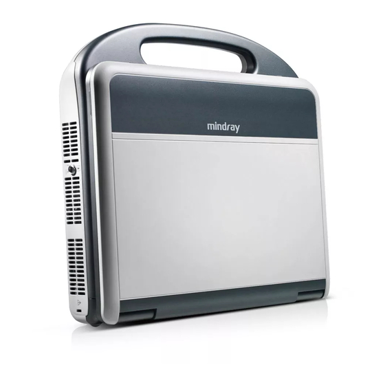
Introduction of Each Unit Name Function Monitor Displays the images and parameters during scanning. Control Panel Operator-system interface or control. CW pencil probe port Connects the pencil probe to the main unit Handle Used for carrying the system. Connects a probe to the main unit; or connects a probe Probe port extend module. -
Page 40: Mobile Trolley
Mobile trolley The system can be configured with 2 models of mobile trolley: UMT-200 and UMT-300. Mobile Trolley is used for placing the ultrasound system, extend modules and etc. 1. Be sure to connect the equipotential wire before WARNING: inserting the power plug into the receptacle; be sure to remove the power plug from the receptacle before disconnecting the equipotential wire;... - Page 41 UMT-200 UMT-300 System Overview 2-11...
- Page 42 Name Function Displays the image and parameters during Display module scanning Probe cable hook Probe cable hanger Ultrasound system Probe holder Used for placing probes temporarily Operating platform To place the ultrasound system Adjustable telescopic column Raise the handle to adjust height of the switch platform Built-in DVD RW drive...
- Page 43 Power Panel Name Function Circuit breaker Switch on or off the mains power supply Power inlet AC power inlet Indicates if the trolley is connected to the mains power supply: If connected with mains power and the breaker is on, the Power indicator indicator illuminates in green color If not connected with mains power or the breaker is off, the...
-
Page 44: Extend Modules
Extend Modules There are four extend modules available for the system: Probe extend module I/O extend module V/A extend module ECG module 2.8.1 Probe Extend Module Overview To connect the module: a) Insert the module connector into the probe port with its bulge facing to the right side of the system (when you are facing to the front of the system). -
Page 45: I/O Extend Module
2.8.2 I/O extend module Overview Symbol Function <1>, <2> Connects USB devices. USB port <3> ECG Port Connects the ECG module <4> Connects serial port devices Serial port Used for audio signals of Doppler mode sound <5>, <6> Audio output port from DVD output or audio comments Reserved.(Connects a microphone used for <7>... -
Page 46: V/A Extend Module
2.8.3 V/A Extend Module Overview The module is connected to the USB port of the main unit via a USB cable. < > < > < > < > Name Function <1>, <2> Audio input port Used for audio signal input Used for composite signal video input <3>... -
Page 47: Ecg Module
2.8.4 ECG module Overview To connect the ECG module, the system should also be configured with the I/O extend module. The ECG module is connected to main unit via connection to the I/O extend module. Name Function Used for ECG signal input ECG lead port Connection Connect the ECG module to the main unit via the I/O extend module, see "2.8.2 I/O... -
Page 48: Control Panel
Control Panel <1> <2> <3> <4> <5> <6> <7> <8> <9> <10> <11> <12> <13> <14> <15> <16> <18> <17> <19> <20> <21> <22> <23> <24> <35> <25> <36> <38> <37> <26> <29> <40> <41> <42> <27> <30> <39> <28> <31>... - Page 49 Name Description Function Press to select the soft menu items displayed on the bottom of the screen. Soft menu <5> controls 5 Refer to the subsequent contents for specific functions. Press to select the soft menu items displayed on the bottom of the screen. Soft menu <6>...
- Page 50 Name Description Function Rotate to increase or decrease the image gain. <24> iTouch Press to optimize the image, serving as a one-key optimization. Patient <25> Patient Press to enter the [Patient Info] screen. Information <26> Exam Exam Type Press to select an exam mode and a probe. <27>...
- Page 51 Name Description Function Rotate to adjust image parameters or direction of comment arrows. Multifunctional <50> knob Press to show the menu, rotate to select the item. Indicates if the main unit is connected to the power supply. If not connected, the indicator does not <51>...
-
Page 52: Symbols
2.10 Symbols This system uses the symbols listed in the following table, and their meanings are explained as well. Symbol Description Type-BF applied part Caution AC (Alternating current) Battery Status Indicator Power button Probe port Probe connection unlocked symbol Probe connection locked symbol I/O extend port USB port Network port... -
Page 53: System Preparation
System Preparation Move/Posit the System Please read and understand the safety precautions before placing the system to ensure safety for both operator and device. 1. Turn off the power and disconnect the system from all peripherals. 2. Carry the system by holding the handle. 3. -
Page 54: Powered By Batteries
If the system begins to function improperly – immediately stop scanning. If the system continues to function improperly – fully shut down the system and contact Mindray Customer Service Department or sales representative. If you use the system in a persistent improperly functioning state –... - Page 55 2. If you find anything not functioning properly, this may indicate that the system is defective. In this case, shut down the system immediately and contact Mindray Customer Service Department or sales representative. When you start the system or switch between probes, you will hear clicking NOTE: sounds –...
-
Page 56: Powering Off The System
3.3.2 Powering OFF the System You need to follow the correct procedures to power off the system. In addition, after you upgrade the software or when the system is down, you need to power off and restart it. If you will not use the system for a long period of time, you shall: 1. -
Page 57: Standby
3.3.3 Standby Definition of standby: in a normal environmental temperature and humidity condition, the system is connected with only one probe while no other external devices or extend modules are connected, only 3V3_STB and 5V_STB power supply is available and in the meantime, the standby indicator is in orange. -
Page 58: Connecting /Disconnecting A Probe
1. When connecting or disconnecting a probe, place it in a CAUTION: proper position, to prevent the probe from falling off or becoming damaged. 2. Only use the probes provided by Mindray. Aftermarket probes may result in damage or cause a fire. 3.4.1 Connecting a Probe... -
Page 59: Connecting The Footswitch
Connecting the Footswitch Connect the footswitch to the main unit via a USB port. As shown in the following figure. Set the functions of the footswitch in the [Key Config] page. Refer to "14.1.7 Key Config" for details. Connecting/ Removing a USB Memory Device DO NOT directly remove a USB memory device;... -
Page 60: Graph /Text Printer
Graph /Text printer Connecting a local printer As shown in the figure below, a graph /text printer has a power cord and data cable. The power cord shall be directly connected to a protective grounding wall receptacle as required. Power cord Data cable USB connector 1. -
Page 61: Video Printer
Printers listed in "2.5 System Configuration" have drivers installed already. Click [Printer Attribute] to see the printer attribute. 5. Click [OK] to finish the installation. Add Network Printer After the system is connected into a LAN, enter the "[Setup] -> [Peripheral Preset] -> [Printer] ->... - Page 62 4. Install the printer driver (steps are the same as of graph/text printers; please refer to relevant chapters for details). Printers listed in "2.5.2.3 Peripherals Supported" have drivers installed already. 5. Add a print service: (1) Open "[Setup] → [Peripheral Preset] → [Print Service]" screen. (2) Click [Add Service] to enter the following page.
-
Page 63: Basic Screen And Operation
Basic Screen and Operation 3.9.1 Basic Screen The following diagram maps out the different areas in the screen: Exam Acoustic Hospital Name MI/TI Time Power Freeze Logo Accession# icon Exam Patient Information Probe Operator Mode icon Image Parameter and Image area Menu Area Thumbnail Area of Images Stored... - Page 64 Acoustic power & MI/TI Display the acoustic power, including the acoustic power, MI (Mechanical Index) and TI (Thermal Index). Freeze icon The freeze icon means the image is frozen. Patient Information Displays patient name, ID, gender and age etc. Enter the patient information through the "Patient Info"...
- Page 65 Menu title Page-turning button Drop-down list button Items Page-turning button Menu title Displays the menu name. Divide the menu items according to measurement conditions. Page-turning button When there are too many items in a menu, the items will be divided into more than one page.
- Page 66 For tab items in the menu: e.g. the “Right” and “Left” items in the measurement menu. Rotate the multifunctional knob to navigate the tab, and press the knob to select the tab. Parameter Area Display the image parameters for the activated image window. If there are more than one imaging modes, the system displays the parameters of each image mode respectively.
- Page 67 Page-turning: Use the up/down keys in soft menu controls <4> to turn pages up or down; you can operate the items only when they are highlighted. Mode switching: Left / right keys in <4> are used to switch among the modes. The soft menu items vary depending on the mode.
-
Page 68: Basic Operations Of Screens
3.9.2 Basic Operations of Screens A screen consists of title, page tabs, contents and buttons, as shown in the following figure: Title Content Control button Composition Description The title bar is used to give a description for the content and Title Bar function of the screen. -
Page 69: Exam Preparation
Exam Preparation Before examining a new patient, press <End Exam> to end the CAUTION: exam of the previous patient, update the patient ID and information, to avoid mixing data of the next new patient. To Start an Exam You can start a patient exam in the following situations: New patient information: Enter the patient information, if it is a new patient, refer to "4.2.1 New Patient Information"... -
Page 70: New Patient Information
4.2.1 New Patient Information The "Patient Info" screen is shown as follows (Take abdomen exam for example): Place the cursor onto the targeted box. The field box is highlighted and a flashing cursor appears. Information can be entered or selected from the options. You can also change the cursor position by <Tab>, <Enter>... - Page 71 DOB (Date of birth): You can either enter the birth date of a patient manually according to the format displayed in the field, or click to select the date. In the table, you can select the desired year (or enter it manually); month and day, then click [OK] to finish it. Age: Auto generated age: once the DOB is entered, the system can display an auto-generated age in the field box, the unit can be “Years”, “Months”...
- Page 72 Exam Type Information Description According to the entered index (can be selected in the drop-down list); including LMP (last menstrual period), IVF (in vitro fertilization), PRV (previous exam date), BBT (basic body temperature)), the system can automatically calculate GA and EDD (estimated delivery date); or, calculates GA and LMP according to the EDD and entered date.
- Page 73 Exam Type Information Description None (Pediatrics) 3. Operating Information Accession #: exam number used in DICOM. It should be entered within 16 letters or characters; “\” is not permitted. Diagnostician: people who is responsible for the exam. "\", "^","=" and "," are not permitted.
-
Page 74: Retrieve Patient Information
4.2.2 Retrieve Patient Information 4.2.2.1 iStation The patient data can be obtained in iStation from the system hardware or USB memory device. You can enter the searching conditions for the patient. 1. To enter iStation screen (the screen is shown as follows): Press <iStation>... - Page 75 [Continue Exam]: click to continue an unfinished exam that is carried out within 24 hours. [Review]: click to switch to the Review screen. [Exit]: click to exit to iStation dialogue box. 4.2.2.2 DICOM Worklist When the DICOM basic package is configured and the Worklist server has been set, click [Worklist] in the "Patient Info"...
-
Page 76: Select An Exam Mode And Probe
Select an Exam Mode and Probe. If the exam mode is changed during a measurement, all CAUTION: measurement calipers on the image will be cleared. The data of general measurements will be lost, but the data of application measurements will be stored in the reports. 4.3.1 Supported Exam Modes The system can be configured with applications including abdominal, gynecology,... - Page 77 Select the exam mode (when more than one probe are connected): (1) Press <Exam> to open the following dialog box. (2) Roll the trackball and press <Set> to select the exam mode, and use the left/right keys of the soft menu controls to switch the probe. To save the current settings for the current exam mode quickly: (1) Press <Exam>...
-
Page 78: Select The Imaging Mode
Select the Imaging Mode Use the corresponding keys in the control panel to enter the imaging modes. For the detailed operations in each imaging mode, please refer to “5 Image Optimization”. Activate & Continue an Exam 4.5.1 Activate an Exam Select an exam that is finished within 24 hours, click [Activate Exam] in “iStation”... -
Page 79: End An Exam
4.6.2 End an Exam Before examining a new patient, press <End Exam> to end the exam of the previous patient, update the patient ID and information, to avoid mixing data of the next new patient. To end an exam, you can do one of the following: Press <End Exam>... -
Page 80: Anonymous Patient Exam
Anonymous Patient Exam The system can also carry out image scanning and measurement even though no patient information is available: Deselect "Save image without patient info" in "[Setup] -> [System Preset] -> [General]". When saving an image, the system pops up the Patient Info screen to ask for the patient information. -
Page 81: Image Optimization
Image Optimization 1. The images displayed in this system are only reference WARNING: for diagnosis. Mindray is not responsible for the correctness of diagnostic results. It is the responsibility of the clinician, who performs the exam, to capture the correct diagnostic results. -
Page 82: Image Adjustment
Image Adjustment Before optimizing the image by adjusting image parameters, adjust the brightness and contrast of the monitor to the best. Requirement Available Operations Adjust gain Adjust TGC To modify the brightness Adjust [A. power] (do try to adjust gain first before increasing the acoustic power) Adjust [Dyn Ra.] Adjust [Gray Map]... - Page 83 Use left/ right controls in soft menu controls <4> to switch among the modes. The soft menu items vary depending on the mode. The menu navigation will cause the change of the menu, while the change of the menu will cause the menu navigation.
-
Page 84: B Mode Image Optimization
B Mode Image Optimization B mode is the basic imaging mode that displays real-time images of anatomical tissues and organs. 5.3.1 B Mode Exam Protocol 1. Enter the patient information, and select the appropriate probe and exam mode. 2. Press <B> on the control panel to enter B mode. 3. - Page 85 Depth Description This function is used to adjust the display depth of sampling, the real-time value of which is displayed on the image parameter area in the upper left corner of the screen. To change depth, press keys in the lower right corner of the control panel. Operation Press key to decrease the depth;...
- Page 86 Adjust through the [A. power] item in the soft menu or menu. Operation The adjusting range vary depending upon probe types. Generally, increasing the acoustic power will increase the brightness and Effects contrast of the image as well as the force of penetration. You should perform exams according to actual situation and follow the Impacts ALARA Principle.
- Page 87 Line Density Description The function determines the quality and information of the image. Adjust through the [Line Density] item in the soft menu or menu. Operation The higher the line density, the higher the resolution, and the lower the Effects frame rate.
- Page 88 When you invert or rotate an image, the “M” mark will change its position correspondingly on the screen; the M mark is located in the upper left corner of the imaging area by default. iBeam Description This function is used to superimpose and average images of different steer angles to obtain image optimization.
- Page 89 TSI (Tissue Specific Imaging) Description The TSI function is used to optimize the image by selecting acoustic speed according to tissue characteristics. Select among the TSI modes through the [TSI] item in the soft menu or Operation menu. The system provided 4 ways of optimization for specific tissues: general, muscle, fluid and fat.
- Page 90 Adjust through the [LGC1]-[LGC8] item in menu. Operation The 8-segment LGC indicate the corresponding image areas on the main screen. Increasing the LGC value will increase the gain of the corresponding image areas. HScale Description Display or hide the width scale (horizontal scale). The scale of the horizontal scale is the same as that of vertical scale (depth), they change together in zoom mode, or when the number of the image window changes.
-
Page 91: M Mode Image Optimization
M Mode Image Optimization 5.4.1 M Mode Exam Protocol 1. Select a high-quality image during B mode scanning, and adjust to place the area of interest in the center of the B mode image. 2. Press <M> on the control panel, and roll the trackball to adjust the sampling line. 3. - Page 92 5.4.3 M Mode Image Optimization Gain Description To adjust the gain of M mode image. The real-time gain value is displayed in the image parameter area in the upper left corner of the screen. Rotate the <iTouch> knob clockwise to increase the gain, and Operation anticlockwise to decrease.
- Page 93 IP (Image Processing) Description IP is a combination of several image processing parameters, which is used for a fast image optimization. The IP combination number is displayed in the image parameter area in the upper left corner of the screen. The M IP combination parameters include dynamic range, edge enhance, and M soften.
- Page 94 Select among the maps through the [Gray Map] item in the soft menu or Operation menu. You can also adjust through the grayscale bar: move the cursor to the grayscale bar and press <Set> on the control panel to adjust. The system provides 8 groups of gray map.
-
Page 95: Color Mode Image Optimization
Color Mode Image Optimization The Color mode is used to detect color flow information, and the color is designed to judge the direction and speed of blood flow. Generally, the color above the color bar indicates the flow towards the probe, while the color below the color bar indicates the flow away from the probe;... -
Page 96: Color Mode Image Optimization
5.5.3 Color Mode Image Optimization Color Gain Description Refers to the overall sensitivity to flow signals, and this function is used to adjust the gain in Color mode. The real-time gain value is displayed in the image parameter area in the upper left corner of the screen. Rotate the <iTouch>... - Page 97 Turn on or off the function through the [B Display] item in the soft menu or Operation menu. B/C Align Description To set and constrain the maximum width of the B mode image to that of the Color ROI. Turn on or off the function through the [B/C Align] item in the soft menu or Operation menu.
- Page 98 Flow State Description This function is used for a fast image optimization by providing an adjustment of 2 parameters, including scales and filters. Adjust through the [Flow State] item in the soft menu or menu. Operation There are 3 levels provided to adjust: L, M, H. Persistence Description This function is to adjust the temporal smooth in Color mode to optimize the image.
- Page 99 Invert Description To set the display mode of the color flow, and the color scale will be inverted when the function is turned on. Turn on or off the function through the [Invert] item in the soft menu or Operation menu.
- Page 100 Select the value through the [Priority] item in the soft menu or menu. Operation The adjusting range is 0-100%. The higher the value, color signals are prior to be displayed; while the Effects lower the value, grayscale signals are prior to be displayed. iTouch Description To optimize image parameters as per the current tissue characteristics for a better image effect.
-
Page 101: Power Mode Image Optimization
Power Mode Image Optimization Power mode provides a non-directionally display of blood flow in the form of intensity as opposed to flow velocity. DirPower (Directional Power Mode) provides the additional information of flow direction towards or away from the probe. 5.6.1 Power Mode Exam Protocol 1. - Page 102 5.6.3 Power Mode Image Optimization Power Gain Description Refers to the overall sensitivity to flow signals, and this function is used to adjust the gain in Power mode. The real-time gain value is displayed in the image parameter area in the upper left corner of the screen. Rotate the <iTouch>...
-
Page 103: Pw/Cw Doppler Mode Optimization
PW/CW Doppler Mode Optimization PW (Pulsed Wave Doppler) mode or CW (Continuous Wave Doppler) mode is used to provide blood flow velocity and direction utilizing a real-time spectral display. The horizontal axis represents time, while the vertical axis represents Doppler frequency shift. PW mode provides a function to examine flow at one specific site for its velocity, direction and features;... - Page 104 Display F 2.5 G 60 PRF 3.6k WF295 SVD 8.8 SV 3.0 Frequency Gain Pulse SV Size Repetition (Wall Position Parameters Frequency Filter) Display F 3.3 G 30 WF407 PRF 7.3k SVD 35.0 Frequency Gain WF (Wall Pulse Repetition Parameters Filter) Frequency PRF Position...
- Page 105 Select the frequency value through the [Frequency] item in the soft menu Operation or menu. Or adjust it in the image parameter area. Values of frequency vary depending upon the probe types. Select the frequency according to the detection depth and current tissue characteristics.
- Page 106 Note: heart rate value obtained by auto calculation may be of deviation, Impacts please adopt manual measurement or ECG function (optional) to get the precise value. Auto Calc Cycle Description To set the number of heart cycle for auto calculation. Click [Auto Calc Cycle] on the soft menu or the menu to select the cycle Operations number.
- Page 107 This function facilitates to specify the time information of special points, and Effects makes it easier to identify the cardiac cycles and detect more details. Colorize and Colorize Map Description Colorize function provides an imaging process based on color difference rather than gray distinction.
- Page 108 Turn on or off the function through the [Duplex] / [Triplex] in the soft menu Operation or menu. HPRF Description HPRF mode is used when detected velocities exceed the processing capabilities of the currently selected PW Doppler scale or when the selected anatomical site is too deep for the selected PW Doppler scale.
- Page 109 PW Steer Description This function is used to adjust the scan angle of linear probes, so as to change the angle between the transmitting beam and flow direction. Adjust through the [PW Steer] item in the soft menu or menu. Operation Values of steering angles vary by probes.
-
Page 110: Anatomical M Mode
Anatomical M Mode Items that appear in the menu or the soft menus are dependent upon preset, which can be changed or set through "[Setup] -> [Image Preset]"; please refer to "5.16 Image Preset" for details. Anatomical M images and Color Anatomical M images are CAUTION: provided for reference only, not for confirming a diagnosis. - Page 111 During Free Xros M mode imaging, menus for B mode, Free Xros M mode and other modes are displayed in the soft menu at the same time, use the left/right keys of soft menu controls <4> to switch the menus. Parameters consistent with those in M mode are not to be introduced, please refer to relevant section of the M mode, while special items of the Free Xros M mode will be introduced in the following.
-
Page 112: Free Xros Cm (Curved Anatomical M Mode)
5.8.2 Free Xros CM (Curved Anatomical M Mode) Free Xros CM images are provided for reference only, not for CAUTION: confirming a diagnosis. Please compare the image with that of other machines, or make diagnosis using none-ultrasound methods. In Free Xros CM mode, distance/time curve is generated from the sample line manually depicted at anywhere on the image. -
Page 113: Tdi
TDI mode is intended to provide information of low-velocity tissue motion, specifically for cardiac movement. There are 4 types of TDI mode: Tissue Velocity Imaging (TVI): This imaging mode is used to detect tissue movement with direction and speed information. Tissue Energy Imaging (TEI): This imaging mode reflects the status of cardiac movement by displaying the intensity of tissue, the brighter the color the less the intensity. -
Page 114: Tdi Image Parameters
5.9.2 TDI Image Parameters In TDI mode scanning, the image parameter area in the upper left corner of the screen will display the real-time parameter values as follows: Display F 3.3 G 38 PRF 0.4k WF 3 Parameter Frequency Gain TVI IP WF (Wall Filter) Display... -
Page 115: Tdi Image Optimization
5.9.3 TDI Image Optimization In TVM mode, adjustable parameters are the same as those in B, M, and TVI modes; please refer to the relevant contents for details. Items that appear in the menu or the soft menus are dependent upon preset, which can be changed or set through "[Setup] ->... - Page 116 5.9.4.1 TDI QA Screen Description 1---TVI Cineloop window Sample area: indicates sampling position of the analysis curve. The sample area is color-coded, 8 (maximum) sample areas can be indicated. 2---B Cineloop window Tips: Images in the TVI cineloop window and B cineloop window are the frozen image of the same moment;...
- Page 117 5.9.4.2 Basic Operations of TDI QA Selecting TIC Analysis Image Range A range of frames is selected for the TDI quantitative analysis in Cine mode (before accessing TDI QA). Only the frames in this range are used for the TDI quantitative analysis.
- Page 118 Delete ROI Press <Clear> to clear out the last ROI; click [Delete All] on the soft menu to clear out all ROIs. The corresponding traces for the deleted ROIs are erased from the plot. Deleting an ROI causes the ROIs to be deleted from all frames in the analysis loop. Tips: The saved ROIs can be a mixture of elliptical and freehand ROIs.
-
Page 119: Color M Mode
5.10 Color M Mode Color M mode provides information of color flow or tissue movement on the M mode images to indicate cardiac motion state. It is highly sensitive to the flow or tissue movement. The Color M mode includes Color Flow M mode and Color Tissue M mode (also known as TVM). - Page 120 ROI Adjustment The ROI size and position determine the size and position of the color flow or color tissue displayed in the Color M mode image. Set the position of the sampling line by moving the trackball left and right, and set the ROI position by moving the trackball up and down.
-
Page 121: Note Before Use
5.11 3D/4D Tips: You can select 4D optional module. 4D module includes 4D and Static 3D functions. You can also select Smart3D optional module only. 3D/4D imaging is largely environment-dependent, so the images obtained are NOTE: provided for reference only, not for confirming a diagnosis. Please compare the images with that of other machines, or make diagnosis using none-ultrasound methods. -
Page 122: Overview
Image quality in B mode (2D image quality) Before entering 3D/4D capture, optimize the B mode image to assure: High contrast between the desired region and the AF surrounded. Clear boundary of the desired region. Low noise of the AF area. Scanning technique (only for Smart3D) Stability: body, arm and wrist must move smoothly, otherwise the restructured 3D image distorts. - Page 123 B-section, and YZ-paralleled plane is A-section. The probe is moved along the X-axis. ROI (Region of Interest): a volume box used to determine the height and width of scanning volume. VOI (Volume of Interest): a volume box used to determine the area of a sectional plane for 3D imaging.
- Page 124 It can be adjusted both in acquisition preparation status, and in A, B, C sections of review/ 4D imaging status, and a triangle of control point on the curved VOI is displayed. Depending on the view direction, the orientation and the shape (line or dot) of curved VOI vary: View Curved VOI...
- Page 125 e. Front/Back f. Back/Front Tips: Changing the view direction only changes the 3D/4D image; images of the 3 sections do not change. Probe A 2D imaging probe can be applied for Smart 3D imaging, however, to realize Static 3D imaging or 4D imaging, a volume probe should be selected. Sectional plane The principle of 3D imaging is to render a 3D image from multiple 2D image information.
- Page 126 The current window’s icon is highlighted, e.g., the icon shows that A window is the current window. A, B, C section images are illustrated as the following sections of 3D image. Section A: corresponds to the 2D image in B mode. Section A is the sagittal section in fetal face up posture, as shown in the figure A above.
-
Page 127: 4D Preset
5.11.3 3D/4D Preset 5.11.3.1 Shortcut Key Preset The system supports setting shortcut key to enter 3D/4D imaging. Assign a key as user-defined 3D/4D key, the setting path is “[Setup] → [System Preset] → [Key Config]”. Refer to “14.1.7 Key Config” for details. 5.11.3.2 Menu Preset Open the Menu Preset screen via “[Setup] →... - Page 128 General Parameters Preset Display Format: to set the image display format in 3D image viewing status. Tool: to set the edit type in image edit mode. Edit Depth: to set the edit depth in image edit mode. MPR Line: to set the display manner of MPR Line in image rendering mode. Parameter Package Preset There are five presettable parameter packages for each mode.
-
Page 129: Smart 3D
Select Default Preset Package for Sub-modes After setting preset packages, you can select the default preset package for sub modes. See the figure below: 5.11.4 Smart 3D 5.11.4.1 Basic Procedures for Smart 3D Imaging In Smart 3D image scanning, if the probe orientation mark is oriented to the NOTE: operator’s finger, please perform the scanning from right to left in linear scan;... - Page 130 Method You can capture images by Linear scan or Fan scan. Linear scanning Move the probe across the surface. See the following figure. Fan scanning Rotate the probe once from the left to the right side (or from the right to the left) to involve the whole region desired.
- Page 131 Type Parameter Description Reserve To reserve the VOI edge line to be plane. Curve Provides 5 parameter packages. The package name as Parameter well as all the parameters can be preset. Parameter package packages of each mode are independent (vary with the imaging mode).
- Page 132 A small ROI results in an incomplete 3D image, which can be corrected by resetting ROI after acquisition. For details, please refer to “Reset ROI”. 4. Click [Start] to begin the acquisition. 5. Perform the acquisition according to the scanning technique stated above. (Take fan scanning as an example).
- Page 133 Parameter Description Function: set Surface as 3D image rendering mode. This is helpful for surface imaging, such as fetus Surface face/hand or foot. Tips: you may have to adjust the threshold to obtain a clear body boundary. Function: set Max as 3D image rendering mode, displays the maximum intensity of gray values in the ROI.
- Page 134 Parameter Description Function: using the lines to show the position information of the other sections on a section image or 3D image. MPR Line Selection: Entire, Partial, Off. Entire means to display the whole line crossing the section image. Partial means to display part of the line at both ends of the MPR line.
- Page 135 When 3D image or the MPR the direction of which is the same as 3D image is active, a control point is displayed on the 3D image, roll the trackball to move the control point. Section Image Viewing The principle of 3D imaging is to render a 3D image from multiple 2D image information. You can move the MPR line to view the different position of the section image.
- Page 136 To understand the sectional plane, please refer to “5.11.2 Overview”. Procedures (1) Set a section (A, B or C) as the current window. (2) Click [Adjusting VOI] to be “Off” to enter the sectional plane viewing. (3) Roll the trackball to view the sectional plane. Positions of the other two sectional planes are indicated in the selected plane.
- Page 137 Rotating the Image The system supports the following rotation modes: Sphere center rotation Axial rotation Auto rotation Sphere center rotation Rotate the 3D image around the center point of the 3D image. Procedures a) Set 3D image window as the current window. Click [Current Window] to be “3D”...
- Page 138 5. Set Start position and End position: Start position: roll the trackball to view to a certain position, click [Set Start Pos]. End position: roll the trackball to view to a certain position (after you rotate the image), click [Set End Pos]. 6.
- Page 139 Procedures (1) Enter image editing status by clicking [Edit]. (2) Select an edit type. (3) Set cut depth. (4) Roll the trackball and press the <Set> to position the start point, roll the trackball to set a region and press the <Set> again, the selected region will be cut from the 3D rendered image.
- Page 140 Type Parameters Description Undo To undo the last cut only. Redo To restore the cut region. Other Operations Undo All To undo all cuts since you entered image edit mode. Done Click to confirm the edit. Tips: when reset ROI, entering cine review, exiting “Accept VOI”, unfreezing the system, or entering acquisition preparation, the system will confirm with you “This operation will clear all edit effect, are you sure to continue?”.
- Page 141 Image review Open an image file to enter the image review mode. In this mode, you can perform the same operations as what you can do in 3D image viewing mode. 5.11.5 4D Note: If the system is power by batteries, you may not enter the mode using the probe extend module, try connecting the 4D probe to the system directly.
- Page 142 Quality Function: to adjust the image quality by changing the line density. Image quality can affect the imaging speed that the better the image quality, the lower the speed, so the frame rate is lower. Range: Low2, Low1, Mid, High1, High2 Other parameters are the same as that of Smart 3D, for details;...
-
Page 143: Static 3D
Parameter Description To set the current frame as the end frame for a cine to be saved. Set End Frame Method: review to a certain frame, and click [Set End Frame]. Auto Play Activate auto play, and set the cine review speed. Tips: when system is frozen, or when open a 4D cine file, rolling the trackball left/right controls the cine frame backward/forward, while rolling the trackball up/down (a range more than 45°) makes the 3D image move forward/backward around Z-axis. - Page 144 In image viewing status, you can perform all operations (except reset ROI) that can be performed in Smart 3D. For details, please refer to “5.11.4.4 Smart 3D Image Viewing”. 8. Return to image acquisition preparation: Press <ESC>, <Update> or <Freeze> to return to image acquisition and perform imaging again if necessary.
-
Page 145: Iscape
5.12 iScape The iScape panoramic imaging feature extends your field of view by piecing together multiple B images into a single, extended B image. Use this feature, for example, to view a complete hand or thyroid. When scanning, you move the probe linearly and acquire a series of B images, the system piece these images together into single, extended B image in real time. -
Page 146: Iscape Preset
The system enters into image viewing status when the acquisition is completed. You can perform operations like parameter adjusting. For details, please refer to “5.12.4 iScape Viewing”. 5. Exit iScape Click [Return], or press <Esc> to return to iScape preparation; or press <B> to return to B mode.If it is in the capture status, click [Exit] in the menu;... -
Page 147: Iscape Viewing
Tips about the probe speed: during image slicing, the system gives feedbacks about the probe moving speed in the form of color and words, the relations are listed as follows: Status ROI Color Tips Speed too low Blue Moving speed of the probe is too low. Appropriate Green None... -
Page 148: Cine Review
Rotate the knob anticlockwise to zoom out the image, the minimum factor is 0.01. Roll the trackball to change position of the magnified image. Press the <Zoom> again to exit the zoom mode. When image displayed is bigger than the image area, the thumbnail is automatically displayed. -
Page 149: Save Image
Click [iScape] item in the soft menu to exit the cine review mode, and there displays the panoramic image. In cine review mode, press <Freeze> on the control panel to return to the acquisition preparation status. Click [Save Cine] to save the images. 5.12.6 Save Image Panoramic image viewing mode: Press <Save>... -
Page 150: Stress Echo
5.13 Stress Echo Stress echo data are provided for reference only, not for CAUTION: confirming a diagnosis. 5.13.1 About the Stress Echo Feature The optional Stress Echo feature allows you to capture and review cardiac loops for multiple-phase (multiple-stage) Stress Echo protocols. It provides tools for ECG-triggered acquisition, display, selection, comparison, evaluation, and archiving of multiple cardiac loops during various stages of the Stress Echo portion of a patient examination. - Page 151 The system displays the real-time imaging screen. If the Stress Echo manual ROI option is selected in the Maintenance dialog box, then the system also displays a region of interest (ROI). If Acquire Mode is set as Full-screen in Maintenance, then no ROI box is displayed. 3.
-
Page 152: Navigation Toolbar
Each saved image will be marked with two times T1 and T2, T1 refers to the total time of the whole acquisition, while T2 means the time the acquisition lasted for a certain stage. 7. To review loops before ending acquisition, click [Review] icon on the lower left part of the screen. - Page 153 4. Sweeping Play: Continuous sweeping playback of loops forward-backward-forward. 5. Labels on/off: hide/display graphics on loops. Specifies loop segment of display. Bookmark Review: turns on/off the bookmark function. Scroll Up: Displays loops in previous view. Scroll Down: Displays loops in next view. Quad/Single: to display all loops of the exam.
-
Page 154: Selecting Preferred Stress Echo Loops (Select Mode)
5.13.4 Selecting Preferred Stress Echo Loops (Select Mode) The selected clips are used for analysis in the review mode and wall motion scoring mode. Select Mode is used for the selection of the best loops of the examination. When acquisition is ended, select mode is enabled automatically, or, select the Select Mode toolbar button at the left corner of the screen. -
Page 155: Review Mode
Selection Description Last Go to “last” Clips. Text “On”/“Off” Function that turns on screen graphic text “On”/“Off”. The function is the same as Labels on/off icon on the top of the screen. Information includes: name of level, name of view, heart rate, time stamp acquisition, timers, frame slider, loop ID, clip control. - Page 156 To display phases side by side for the selected view(s) 1. The system include all phase or view in display, select the rightmost, gray box to the left of each required phase and/or view. The system inserts a checkmark into each selected gray box. 2.
- Page 157 Description Start of sequence/ End of sequence: direct access to first/last loop in series. Step backward/Step forward: frame-by-frame loop review. Decrease speed/increase speed: decrease or increase playback speed. Sweeping play: continuous sweeping playback of loops forward-backward-forward. Clip Length Specifies loop segment of display (Full heartbeat, Systole, Diastole, User-defined, Fixed range).
-
Page 158: Wall Motion Scoring And Reports
End of sequence – displays the last frame of each loop. To set the cine segment Drag the inverted triangle on the cine slider . Click [Apply Edit All] and the edit is applied to all clips. 5.13.6 Wall Motion Scoring and Reports The WMS-Report lists user-assigned wall motion scores and associated data. - Page 159 To assign a wall motion score (WMS): 1. Select the Wall Motion Scoring Mode toolbar button at the top of the screen to activate Wall Motion Scoring Mode. 2. Select a colored number in the lower-right area of the screen. The signification and color used in segments are listed in the table below.
-
Page 160: Maintenance And Protocol
To preview the report for the currently selected mode The Report Preview toolbar button is available only when a printer driver is installed. Select the Report Preview toolbar button at the top of the screen. To print the report for the currently selected mode The Print toolbar button is available only when a laser printer is connected. - Page 161 Item Function Description WMS type Set the methods of chamber segments division. Printer Set the printer used for report printing. To customize the length of systolic duration acquired for a specific heart rate. If “Trigger” of “R-R Systolic” is selected in Protocol QT-Time Table Editor.
- Page 162 Item Function Description Protocol name Enter the protocol name. Stage Set stages for the protocol. Trigger Set the trigger type. WMS model Set the methods of chamber segments division. Displays the acquired loop number as well as the total usable loop Loop usage number.
-
Page 163: Saving Stress Echo Data
1. Select the [Load] button on the right. The system displays the Select Protocol to load window. 2. Select the protocol and then click [OK]. The system displays the name of the selected protocol in the Protocol Name box and lists the protocol's phases and views. -
Page 164: Exiting The Stress Echo Feature
5.13.9 Exiting the Stress Echo Feature When you exit the Stress Echo feature, the system removes the display of the Stress Echo screen and displays the Patient Info screen for entering new patient information. If later review of the stress echo data is required, then you must save the stress echo data before exiting the Stress Echo feature. -
Page 165: Contrast Imaging
5.14 Contrast Imaging 2D contrast imaging is used in conjunction with ultrasound contrast agents to enhance the imaging of blood flow and microcirculation. Injected contrast agents re-emit incident acoustic energy at a harmonic frequency which is much more efficient than the surrounding tissue. -
Page 166: Contrast Image Parameters
Click [Exit] on the menu in the top-left part of the screen to exit contrast imaging mode, or press <B> to return to B mode. 5.14.2 Contrast Image Parameters Parameter Area Display When entering contrast imaging mode, the screen displays the contrast image. If the [Dual Live] on the soft menu is “ON”, both the contrast image (marked with “... -
Page 167: Measurement, Comments And Body Marks
The time begins at 0. In live mode, the elapsed time is displayed. For example, means the elapsed time is 8 seconds. If the image is frozen during timing, the timer stops working and the elapsed time will be displayed after defreezing the image. Set [Timer 1] or [Timer 2] to “OFF”... -
Page 168: Elastography
5.15 Elastography Elastography images are provided for reference only, not for CAUTION: confirming diagnoses. Elastography imaging is an option. Linear probes L12-4s and L14-6Ns under thyroid and breast exam modes support the Elastography function. Items that appear in the menu or the soft menus are dependent upon preset, which can be changed or set through "[Setup] ->... -
Page 169: Mass Measurement
To adjust the image smoothness. Adjust using the [Smooth] on the soft Operation menu. The system provides 5 levels of smooth function: the bigger the value the stronger the effect. Opacity Description To adjust the opacity feature of the Elasto image. Use [Opacity] on the soft menu. -
Page 170: Image Preset
5.16 Image Preset In the Image Preset interface, you can preset image parameters of exam modes and soft menu and menu layout of imaging modes. 5.16.1 Image Preset The image preset is used to set image parameters for all the probes and a specific probe in a specific exam mode. - Page 171 Parameter Type Description Acoustic Drop-down list To set the default acoustic power. Power TIC, TIB, TIS, to choose the item to be displayed on the Thermal index Radio button screen. To set the default status of colorize function in B mode, Colorize Check box to turn on or off.
-
Page 172: Soft Menu And Menu Preset
Parameter Type Description Radio U/D Flip To set the default vertical flipping mode: Up or Down. button Drop-down Rotation To set the default rotate angle in B mode. list Drop-down list B IP To set the default B IP value. Button Drop-down list... - Page 173 1. Select the probe type: select “Linear” in the corresponding drop-down list. 2. Select image mode: select “B” in the drop-down list. 3. Select image status: [Active] or [Freeze]. 4. Click [Softkey] on the right side of screen to begin the setting. Add the item (s) Select an item in the Available Item list, and click to add the item to the...
- Page 174 5.16.2.2 Menu Preset On Menu Preset page, click Menu on the right side to enter the menu preset page. See the figure below: 1. Click [Image Params] page tab to enter image parameter setting page. 2. Select the probe type: select “Linear” in the corresponding drop-down list. 3.
-
Page 175: Display & Cine Review
Display & Cine Review Image Display 6.1.1 Splitting Display The system supports dual-split and quad-split display format. However, only one window is active at one time. Dual-split: press <Dual> on the control panel to enter the dual-split mode, and using <Dual> to switch between the two images; press <B> on the control panel to exit. -
Page 176: Pan
6.1.4 Procedures: 1. Click [Magnify] on the soft menu to directly enter the pan zooming status; or press <Zoom> in freezing status. Image-in-image is displayed. 2. Click [Magnify] on the soft menu or rotate the multifunctional knob to change the magnification factor. -
Page 177: Cine Review
Press <Freeze> in freeze mode to unfreeze the image, the system continues image scanning. 6.1.6.1 Imaging Mode Switching When Frozen Imaging mode switching in freeze mode follows the following principles: In splitting display B mode, press <B> to exit splitting display mode and display the image of the currently activated window in full screen. -
Page 178: Entering/ Exiting Cine Review
1. Cine Review images can be inadvertently combined CAUTION: in-between separate patient scans. The cine memory must be cleared at the end of the current patient and the onset of the next new patient by selecting the <End Exam> on the control panel. -
Page 179: Cine Review In M Or D Mode
a) In the manual cine review status, click [Auto Play] in the soft menu to activate auto cine review. b) Reviewing speed: In the auto cine review status, click [Auto Play] in the soft menu to adjust the review speed. The available values are ×0, ×1/10, ×1/5, ×1/4, ×1/3, 1/2, ×1, ×2, and ×... -
Page 180: Linked Cine Review
6.2.4 Linked Cine Review The linked cine review refers to review of the images captured at the same moment. Dual live mode(B+C) PW+B duplex mode PW+C+B triplex mode There displays the frame mark on the time mark of M/PW image indicating the current 2D image. -
Page 181: Frame Compare
4. Adjust the image parameters or do other operations (like image zoom in/zoom out, comment) if necessary. 5. Save the image. 6. In non-single display format, image will be saved in BMP-format; in single display format, FRM image will be saved in FRM-format, and CIN image file will be saved in CIN-format. -
Page 182: Cine Memory
Cine Memory 6.6.1 Cine Memory Setting There are 2 ways of cine memory split: auto and split. Setting path: select "Auto" or "Split" for cine memory in [Setup] -> [System Preset] -> [Image Preset]. Where, "Auto" for the cine memory indicates the system splits the cine memory as per the number of B image windows. -
Page 183: Ecg
The system can be configured with the optional ECG module. In that case, the ECG signal is displayed on the image, and can be reviewed simultaneously with the image. When the system is connected with the ECG module: The Physio menu is available. The ECG icon including heart-shaped symbol and heart rate symbol are displayed on the screen. -
Page 184: Ecg Operation Basic Procedures
ECG Operation Basic Procedures 1. Connect the ECG device. Set ECG parameters if necessary. Turn off the power supply of the system, and connect the ECG module to the system (For connection, please refer to “2.8 Extend Modules”) Turn on the power supply of the system Place the ECG electrodes on the patient’s body (as shown in the following figure) Right Right... -
Page 185: Parameter Description
Menu Preset Click [Menu Preset] in the Image Preset screen to enter the menu preset page, and click “Physio” page tab to go for the setting. Parameter Description Display Function: to set if to display ECG trace on the screen. Function: to set the vertical position of the ECG trace on the image display. -
Page 186: Ecg Review
ECG Review When an image is frozen, the ECG waveform will be frozen at the same time. When images are reviewed with the ECG electrodes connected, the ECG waveform is the reference for time. After the images are frozen, all real time images are in the status of linked review. The frame position marker indicates the time relationship between the currently reviewed 2D image and the ECG trace or M/D image. -
Page 187: Measurement
Measurement You can perform measurements on a zoomed image, cine reviewing image, real-time image, or frozen image. For measurements details, please refer to the [Advanced Volume]. 1. Be sure to measure areas of interest from the most WARNING: optimal image plane to avoid misdiagnosis from inaccurate measurement values. -
Page 188: General Measurements
General Measurements 8.2.1 2D General Measurements 2D general measurements refer to general measurements on images of B, Color, Power or iScape imaging modes. The measurements listed below can be performed: Measurement Function Tools Distance Measures the distance between two points of interest. The distance between probe surface and the probing point along Depth ultrasound beam. -
Page 189: M General Measurements
8.2.2 M General Measurements M general measurements refer to general measurements on M mode, Color M mode, Free Xros M mode images. The measurements listed below can be performed: Measurement Function Tools Distance The vertical distance between two points. Time The time interval between any two points. -
Page 190: Application Measurement
Application Measurement The system can be configured with the following application measurement packages corresponding to the application packages (refer to "2.5 System Configuration" for details): Abdomen measurements - Used for measurements of abdominal organs (liver, gall bladder, pancreas and kidney, etc.) and large abdominal vessels. OB measurements- Used for measurements of fetal growth indexes (including EFW) as well as GA and EDD calculations. -
Page 191: Measurement Accuracy
Measurement Accuracy Table 1 Error of 2D Images Parameter Value Range Error Within ±3%; or when the measured value is Distance Full screen less than 40 mm, the error is less than1.5 mm. Within ±7%; or when the measured value is Area (Trace) Full screen less than 16 cm... - Page 192 Table 5 B Performance Probe D7-2s DE11-3s C6-2Gs 6LB7s_C 6LB7s_L C11-3s L16-4Hs Expected ≤ ≤ ≤ ≤ ≤ ≤ ≤ Lateral 2(Depth 1(Depth 2(Depth 1(Depth 1(Depth 1(Depth 1(Depth Resolution ≤60) ≤40) ≤60) ≤40) ≤60) ≤40) ≤40) (mm) Expected ≤ ≤ ≤...
- Page 193 Probe 7LT4s P7-3Ts 3C5s 2P2s 6CV1s 7L5s ≤1(Depth ≤3(Depth Expected ≤80) ≤80) Lateral ≤1(Depth ≤2(Depth ≤1(Depth ≤1(Depth ≤2(80< ≤4(80< Resolution ≤60) ≤60) ≤40) ≤60) Depth≤ Depth≤ (mm) 130) 160) ≤1(Depth ≤1(Depth Expected ≤80) ≤80) ≤ Longitudinal ≤1(Depth ≤1(Depth ≤1(Depth 0.5(Depth ≤2(80<...
- Page 194 Table 9 Elastography Performance Probe L12-4s L14-6Ns Expected Max Detect Depth (mm) ≥30 ≥30 Expected Lateral Resolution (mm) 10.5 10.5 Expected Area Relative Deviation within Within the selected field range, the measurement accuracy is ensured within the NOTE: range mentioned above. The accuracy specifications are performance in the worst conditions, or based on the real test for the system, regardless of acoustic speed error.
-
Page 195: Comments And Body Marks
Comments and Body Marks Comments (Annotations) Comments can be added to an ultrasound image to bring attention, notate or communicate information observed during the examination. You can add comments to: zoomed image, cine review image, real-time image, frozen image. You can type the character as comments;... -
Page 196: Adding Comments
Home of comments Move the cursor to the desired location for a comment and click [Set Home]. The current position of the cursor is set to be the default position of the comment adding. When clicking [Home], the cursor will return to the default setting position. Assign the user-defined key for the set home function in “[Setup] →... - Page 197 Typing comment characters 1. To set the comment location: Roll the trackball or press directional keys on the control panel to move the cursor to the desired location for comments. 2. To type the alphanumeric characters: Type the alphanumeric characters through the qwerty (The default characters are uppercase).
-
Page 198: Moving Comments
Press <Clear> to clear the trace(s). 4. Press <Set> to finish a tracing. 5. Click <Trace> again to exit the status. 9.1.4 Moving Comments 1. Move the cursor onto the comment that needs to be moved. Press <Set> to select it, and a highlighted box appears around the comment. -
Page 199: Body Marks (Pictograms)
Delete all comments (characters, texts or arrows) Click [Erase All Text] to delete all the comment items on the screen. You can also assign the user-defined key for the function in “[Setup] → [System Preset] → [Key Config]”. Or, press and hold the <Clear> to delete all the comments. Clear comments automatically It can be set if to clear the comment when the image is unfrozen or the probe or exam is changed. -
Page 200: Moving Body Marks
3. Press <Set> to confirm the selection. 4. To adjust the probe position and orientation marker: Roll the trackball to place the probe marker at the correct position. Rotate the multifunctional knob to adjust the orientation. Press the <Set> to confirm the position and orientation of the probe marker and exit the body mark mode. -
Page 201: Patient Data Management
2. The system patient database space is limited, please back up or clear patient data in time. 3. Mindray is not responsible for lost data if you DO NOT follow suggested backup procedures. 10.1 Patient Information Management 10.1.1 Enter Patient Information The general patient information and exam information are entered through the Patient Info screen, for details;... -
Page 202: Image File Management
10.2 Image File Management You can store the image files either in the patient database in the system, or to external memory devices. For a saved image, you can perform operations like image reviewing, analyzing and demonstration (iVision). 10.2.1 Memory Media System supported memory media including: System hard disk USB memory devices: USB flash drive, removable USB hard disk... -
Page 203: Saving Images To The System
Set single frame export format Format You can select the image export format in the “Send To” dialogue box. You can set the JPG compression ratio via “[Setup] → [System Preset] → [General]”. Compression in a JPEG format may result in image distortion. NOTE: Set cine saving length Live Capture... -
Page 204: Quickly Saving Images To Usb Flash Drive
10.2.5 Quickly Saving Images to USB Flash Drive Use user-defined keys to quickly save the single-frame or cine to USB flash drive. The image file is stored in the directory: U disk\ US Export\ patient folder\ exam folder\ Image ID.bmp, where, Patient folder name: patient name + patient ID Exam folder name: exam mode+ exam time To store single-frame image to USB flash drive:... -
Page 205: Image Review And Analysis
10.2.8 Image Review and Analysis You can review and analyze the stored images (only refer to the images stored in the system default path). 10.2.8.1 Review an Image You can review all images stored in an exam, and send, delete or analyze the stored images. - Page 206 3. Double-click a thumbnail to view and analyze an image. Rotating the Multifunctional knob will navigate through thumbnails. The function buttons are described as follows: Exam History: You can select one certain exam from the exam directory to review the images. If entered from iStation, the screen displays the record(s) selected in the iStation.
-
Page 207: Ivision
To exit the image analysis: Press <Freeze> to exit and enter the real-time scanning status. Press <Review> to exit from the image analysis to the Review status. Press <ESC> to return to the previous screen. For BMP-formatted image, click [Exit] at the lower right corner of the image to exit. -
Page 208: Sending Image File
Demonstration item The demonstration items are the image files in the formats that the system supports. You can add the exam data in patient database (D:\PatientData) or system supported image files and folders to demonstration item list. For files and folders in demonstration list, the images in the directory and subdirectory are played one by one, and the system will automatically jump over the files that can’t be opened. -
Page 209: Report Management
For external memory devices (e.g. USB memory devices, DVD-RW, MedSight devices or network storage server): a) PC format transfer: JPG/ AVI, BMP/ AVI, TIFF/ AVI. Where a single-frame image is exported as JPG, TIFF or BMP, and the cine file exported as AVI. b) DCM format transfer: DCM (including single-frame DCM and multi-frame DCM). -
Page 210: Patient Data Management (Istation)
In the iStation or Review screen, click [Send To] to send patient data to an external memory device or network storage server, you can choose if reports are exported with images. See the figure below. To export the report: (1) Check “Export Report” on the screen. (2) Click [OK] to confirm. -
Page 211: Viewing Patient Information
To Enter iStation Press <iStation> on the control panel; or Click [iStation] in the Patient Info screen; or Click [iStation] in the Review screen. The iStation screen is shown as follows: 10.4.1 Viewing Patient Information Data Source Select the data source of patient data, the system patient database is default. Patient list Display patient information, exam mode, number of images and cines, exam state, backed up or not. -
Page 212: Searching A Patient
10.4.2 Searching a Patient (1) Select the data source. (2) Set search items of Name, ID, DOB, and Exam Date in the "Item" drop-down list. (3) Enter the keyword in accordance with the “Item” selected, and the system searches and displays the results in the patient list. (4) When you select a patient in the patient list, the images of this patient will be displayed at the bottom of the screen. -
Page 213: Examinations
Tips: The recycle bin will be cleared after the system is powered off. To recover the deleted patient data, click at the lower right corner of the screen to enter the Patient Recycle Bin screen. (1) Select items to be recovered in the list. (2) Select operations: Click [Restore Items] to restore the item back to iStation. -
Page 214: Print Job Management
2. Click [Send To]. 3. Select [Network Storage] in the Send To dialogue box, and select the PC server on the right side. 4. Select PC transfer format and check if to send report. 5. Click [OK] to start sending. User-defined key for network storage Send Image to Network Storage: to send image(JPG format) to the default network server. - Page 215 (4) After the writing process is completed, click to pop up the Disc Option dialogue box, and select [Eject] to eject the CD/DVD. To erase data from a CD/DVD (1) Put the CD/DVD in the tray. (2) Click the symbol to pop up the Disc Option dialogue box, as shown in the figure below.
-
Page 216: Patient Task Management
10.8 Patient Task Management Click at the lower right corner of the screen to pop up the following dialogue box: The system supports three types of task management: Storage Task: displays the DICOM storage task. Print Task: displays the DICOM print task. Media Storage Task: DICOM media storage task(including DVD-RW and USB devices) Backup task (system-relevant format): select the exam in iStation and click... -
Page 217: Administration
Task status When there is/are task (s) undergoing, the task management icon displays as , you can click the icon to check the process. When there is any task failed, the task management icon displays as , you can click the icon to check the failure. When the task management icon displays as , it means no task is undergoing or no failure. -
Page 218: Add/ Delete A User
(2) Select the user name in the drop-down list of User Name. (3) Enter password and click [Login]. For emergency users, click [Emergency] directly to log on. To change user: (1) To log out the current user and change to another user, click at the lower right corner of the screen to pop up the following dialogue box: (2) Click [Change User] to pop up the Login dialogue box. - Page 219 2. Click [Add] to enter the following page. 3. Enter the user name (you are not allowed to enter the same name or modify the name already exist). 4. Enter the password and the confirm password (the password is consist of 6-16 characters) 5.
-
Page 220: Modify Password
10.9.5 Modify Password The system administrator can modify password of all users. The operator can only modify his/her own password. To modify the password, the user has to log on the system first. There are two ways to modify password: modify it on “Admin” page or on “Session Manage”... -
Page 221: Dicom
DICOM NOTE: Before using DICOM, please read the electronic file DICOM CONFORMANCE STATEMENT along with the device. This chapter is confined to the preset, connection verification and DICOM services of the DICOM-configured ultrasound machine, not including SCP configurations like PACS/ RIS/ HIS. - Page 222 3. Enter the name. Tips: you need to restart the system to make the modification effective (press the power button and select ”Shut Down” to power off the system, and then wait for a while to power on the system.). Click to open the connecting management box: 11-2 DICOM...
-
Page 223: Dicom Local Setting
Name Description If “DHCP” is selected, IP address will be automatically obtained from DNS DHCP server; if “Static” is selected (using static IP address), you need to enter the / Static IP address. IP address of the system. Address Subnet Used to set different network segment. -
Page 224: Dicom Server Setting
Name Description Application entity title of the ultrasound system. AE Title The AE title here should be the same with the one of the acceptable SCU set in the server. DICOM communication port, which should be the same with the one in the Port server. -
Page 225: Dicom Service Setting
3. DICOM server setting items are described as follows: Name Description Device Name of the device supporting DICOM services IP address of the server Address You can ping other machines to verify connection after entering the correct IP Ping address. Also you can check the connection of the already added server in the list. - Page 226 11.1.4.1 Storage Setting 1. Enter the “Storage” page: “[Setup]→[Network Preset]→[DICOM Service]→Storage. Select device, enter the information. For device setting, please refer to “11.1.3 DICOM Server Setting”. Click [Add] to add the service to the Service list. Select an item in the service list, change the parameters in the above area, and click [Update] to update the item in the service list.
- Page 227 Name Description Interval Time(s) Reserved feature. Refers to time after which the system will stop trying to establish a Timeout connection to the service. Value: 5-60s. Allow If SCP supports this function, then select it. Multiframe Max Framerate Set the frame range of transferring cin file into DCM multi-frame file. SR Storage To enable or disable structured reporting sending.
- Page 228 DICOM print setting items are described as follows: Name Description After you set the server (s) in DICOM Server Setting, the name(s) will Device appear in the drop-down list, select the name of the print server. Service Name Default is xxx-Print, and it can be modified. Application Entity title, here, it should be consistent with that of the print AE Title server.
- Page 229 Name Description Specify quantity of printed files, e.g. STANDARD\2, 3 indicates 6 Display Format images are printed for each page. Configuration Enter configuration information in the field. Info Specify print medium: Paper, Clear Film, and Blue Film. Medium Type Select Blue Film or Clear Film for black and white printing, select Paper for color printing may provide better effects.
- Page 230 To set the AE Title of the scheduled station. For example, if the AE Scheduled Station Title of the Worklist server is M6, then the scheduled station AE Title AE Title here should be M6. Click to add the Worklist service to the service list.
- Page 231 “Scheduled Station AE Title” configured here should be consistent with the one set in the server. For example, when you set “Scheduled Station AE Title” in the Worklist server as M6 (this means you assigned the scheduled exam to M6), then both “Scheduled Station AE Title”...
- Page 232 DICOM MPPS setting items are described as follows: Name Description After you set the server(s) in DICOM Server Setting, the name(s) will Device appear in the drop-down list, select the name of the MPPS server. Service Default is xxx-MPPS, and it can be modified. Name Application Entity title, here, it should be consistent with that of the MPPS AE Title...
- Page 233 Name Description Click to verify if the two DICOM application entities are normally Verify connected. Exit Click to exit the screen. 11.1.4.5 Storage Commitment Setting 1. Enter the “Storage Commitment” page: “[Setup] → [Network Preset] → [DICOM Service]→Storage Commitment. Select device, enter the information. For device setting, please refer to “11.1.3 DICOM Server Setting”.
- Page 234 DICOM storage commitment setting items are described as follows: Name Description After you set the server(s) in DICOM Server Setting, the name(s) will Device appear in the drop-down list, select the name of the storage commitment server. Service Name Default is xxx-SC, and it can be modified. Application Entity title, Here, it should be consistent with that of the AE Title storage commitment server.
- Page 235 DICOM query/retrieve setting items are described as follows: Name Description After you set the server (s) in DICOM Server Preset screen, the name (s) will Device appear in the drop-down list, select the name of the server. Service Default: xxx-Store, and it can be modified Name AE Title Application Entity title...
-
Page 236: Verify Connectivity
11.2 Verify Connectivity If you want to verify connectivity (it is not a must), you can click [Verify] button on the pages of DICOM Service screen respectively. If the verification succeeds, it will prompt “xxx Verify Succeed”. Otherwise, it prompts “xxx Verify Failed”. If verification failed, the possible causes may be: The ultrasound machine can’t communicate normally with the server. - Page 237 (3) Select DICOM in the “Target” list; select a server in the “Storage Server” list. (4) Click [OK] to start the sending. To send images by shortcut key (1) You can save single frame image or multi-frame images to DICOM server by shortcut key: Save Image to DICOM Storage.
-
Page 238: Dicom Print
(2) Set a default storage server as described before. (3) After finishing the setting, you can perform image scanning, and each time you press <End Exam>, the system will send images to the default DICOM storage server. Send image/ clip to DICOM storage while storing image/ clip to hard disk (1) Open [Setup] →... -
Page 239: Dicom Worklist
11.3.3 DICOM Worklist After successfully connected DICOM Worklist server with ultrasound system, you can query patient records from Worklist server, and then import the desired information to your system. To query patient information via Worklist server: (1) Press <Patient> to enter Patient Info screen. (2) Click [WorkList] to enter the WorkList page. -
Page 240: Mpps
Use the automatic query function via Worklist server (1) Enter DICOM Service Preset screen, and open the Worklist page: [Setup]→[Network Preset]→[DICOM Service]→Worklist. (2) Select an item in the service list, and click [Default] to set the server to be the default service. -
Page 241: Query/ Retrieve
(4) Click [OK] to start sending. The system will send all the images stored in the exam record to the storage server, meanwhile, it will send storage commitment to the storage commitment server. To send storage commitment after an exam ends 1. -
Page 242: Dicom Media Storage
3. Select the server in “Server and Service” area for the source and the destination. 4. Enter the query information, such as patient name, patient ID, accession number, exam time, and select keyword for searching. Click [Clear] to empty the entered query information. 5. - Page 243 3. Select destination in the drop-down list (CD/DVD/USB disk) and select “DICOM Format”. 4. Set whether to remove patient exam data or only images from the local hard disk. 5. Click [Backup] to begin storage. If the backup succeeded, there will be a tick marked in the Backup list in iStation screen; otherwise, no tick is marked.
-
Page 244: Structured Report (Sr)
11.5 Structured Report (SR) The system supports DICOM OB/ GYN structured report, Cardiac structured report and Vascular structured report, and for OB, GYN, Vascular and Cardiac exams, structured report functions are included in DICOM storage, DICOM storage commitment and DICOM media storage. -
Page 245: Probes And Biopsy
Probes and Biopsy Note: For details of storage time and condition for disinfected probes or sterilized probes and brackets, please refer to Technical standard for Disinfection of Medical and Health Structures 12.1 Probe The system supports the following probes: Probe Illustration Probe Illustration... - Page 246 V10-4B CW5s 4CD4s P12-4s 7L4s L12-4s P7-3s L14-6Ns P4-2s CW2s 12-2 Probes and Biopsy...
- Page 247 6C2s P7-3Ts L7-3s 7LT4s 3C5s C11-3s 2P2s DE11-3s 6CV1s D7-2s L14-6s For details of probe P7-3Ts, please refer to P7-3Ts Ultrasonic Transducer Operator’s Manual. Probes and Biopsy 12-3...
-
Page 248: Name And Function Of Each Part Of The Probe
12.1.1 Name and Function of Each Part of the Probe The basic structures and corresponding functions of probes are basically the same. The following will take probe 7L4s as an example to illustrate. <1> <3> <2> <4> Name Function It converts the electrical signal into ultrasound signal, making the sound beams focus in the given direction;... - Page 249 12.1.2 Orientation of the Ultrasound Image and the Probe Head The orientation of the ultrasound image and the probe are shown as below. The “Mark” side of the ultrasound image on the monitor corresponds to the mark side of the probe. Check the orientation before the examination (Here takes linear probe as an example).
-
Page 250: Procedures For Operating
12.1.3 Procedures for Operating This section describes general procedures for operating the probe. The proper clinical technique to be used for operating the probe should be selected on the basis of specialized training and clinical experience. Procedures for operating (with biopsy function): Inspection before examination Connection to the ultrasonic diagnostic system... - Page 251 Procedures for operating (with no biopsy function): Inspection before examination Connection to the ultrasonic diagnostic system Examinations Disconnection to the ultrasonic diagnostic system Wiping off the ultrasound gel Washing the transducer with water Draining/drying Disinfection Immersion into disinfectant Removing the transducer from disinfectant Rinsing the transducer into sterile water Draining/drying...
-
Page 252: Wearing The Probe Sheath
12.1.4 Wearing the Probe Sheath A legally marketed probe sheath must be installed over the probe before performing intra-cavitary and intra-operative examination. Protective barriers may be required to minimize disease transmission. Probe sheaths are available for use with all clinical situations where infection is a concern. -
Page 253: Probes Cleaning And Disinfection
The above is a dimension illustration of the 6CV1s probe. You can select the probe sheath according to the actual application situation. 12.1.5 Probes Cleaning and Disinfection After completing each examination, clean and disinfect (or sterilize) the probes as required. When biopsy procedures have been performed, be sure to sterilize the needle-guided bracket. - Page 254 2. DO NOT make the probe to become overheated (more than 55°C) during cleaning and disinfections. High temperature may cause the probe to become deformed or damaged. Cleaning Please refer to the instructions in the manual and follow your hospital policy and procedures for cleaning.
- Page 255 Clean the transducer before disinfecting it.MINDRAY recommends the following solutions to disinfect the transducer. Refer to the instructions provided by the chemical manufacturer concerning concentration of the disinfectant solution, method of disinfection and dilution and cautions during use.Do not soak the transducer connector or the cable near it into water or any solution.
- Page 256 For intra-operative probes, they have to be sterilized after completing each examination. 1. Wear sterile gloves to prevent infection. 2. Clean the probe before sterilizing it. MINDRAY recommends the following solutions to sterilize the probe. Hydrogen Peroxide and Peroxyacetic Acid -based sterilization solution...
-
Page 257: Storage And Transportation
Relative humidity: 20% ~ 95% (no condensation) Atmospheric pressure:700 hPa ~ 1060 hPa 3. When the probe is sent to MINDRAY Customer Service Department or sales representative for repair, be sure to disinfect it and keep it in the carrying case to prevent infection. -
Page 258: Biopsy Guide
If an abnormality is found on the needle-guided bracket, immediately stop using it and contact MINDRAY Customer Service Department or sales representative. DO NOT use a needle-guided bracket when scanning is performed. - Page 259 10. When performing biopsy procedures, use only sterile ultrasound gel that is certified to be safe. And manage the ultrasound gel properly to ensure that it does not become a source of infection. When performing the operation concerning biopsy, wear sterile gloves. 12.
-
Page 260: Basic Procedures For Biopsy Guiding
When using the needle-guided bracket wear sterile gloves to CAUTION: prevent infection. 12.2.1 Basic Procedures for Biopsy Guiding 1. Select the appropriate needle-guided bracket and needle, and install them properly. For details, please refer to “12.2.4 Needle-guided Bracket Inspection and Installation”. Before biopsy guiding, you can preset bracket model, biopsy display and guide line dot type. -
Page 261: Needle-Guided Brackets
A needle-guided bracket is available for purchase as an optional accessory; it is used in combination with the probe. Some of the probes have matched needle-guided bracket and needles. To order needle-guided brackets, contact MINDRAY Customer Service Department or sales representative. - Page 262 Needle-guided bracket Probe NGB-006/ NGB-007 Metal needle-guided bracket: No. Name Description Support of needle-guided Used for installing the needle-guided bracket on the bracket probe. Groove and tab of the Respectively matches with the tab and groove of the needle-guided bracket probe Angle adjusting base There are 3 types of angles available to be adjusted.
- Page 263 No. Name Description Used for determining the angle of the biopsy; different Angle block specifications of blocks can be used. Used for installing biopsy needle; there are five Guiding block specifications of guiding blocks for different biopsy needles. Specification of guiding Matched with the corresponding biopsy needle (14G).
- Page 264 NGB-009 Name Description Support of Used for installing the needle-guided bracket on <1> the transducer. needle-guided bracket Knob fixing Used for fixing the needle-guided bracket on the <2> needle-guided bracket transducer. <3> Groove Match with the tab on the transducer. Hole for installing guiding Used installing...
- Page 265 NGB-010 Name Description Used for installing biopsy needle; there are five Guiding block specifications of guiding blocks for different biopsy needles. Guiding hole of the Used for installing the biopsy needle. biopsy needle Support of Used for installing the needle-guided bracket on the needle-guided probe.
- Page 266 NGB-011 Needle guide Clamping knob of the needle guide Locating Clamp Needle guide hole Locating groove Needle guide rack Grip knob Needle-guided bracket Probe NGB-015 Guiding Groove hole V-shaped guiding block Lock pin Needle type Needle fixing nut adjusting base Needle type dial scale V-shaped cover Clamp...
- Page 267 NGB-016 Name Description Clamp of needle-guided Used for installing the needle-guided bracket on the <1> bracket probe. Groove of the <2> Matches with the tab of the probe. needle-guided bracket <3> Angle adjusting base There are 3 types of angles available to be adjusted. Angle shift sign (30°, 40°, <4>...
- Page 268 NGB-018 Needle guide hole Guiding block Guiding block specification Pinch nut of bracket Angle shift sign Angle pinch nut Angle-adjusting base Angle block Groove Clamp Name of Each Part (NGB-024) Right, left retaining nut Right, left clamp Angle locking nut Angle adjusting block Angle marker Groove...
-
Page 269: Biopsy Preset
NGB-027 Position block Upper clamp Front clamp Pinch nut Intra-cavity probe Front slot Lower clamp Positioning block 12.2.3 Biopsy Preset Enter the biopsy preset page: [Setup]→[System Preset]→“Biopsy”. Bracket preset To set the default bracket for a probe: 1. Select a probe model in the Probe Model list, all the supported bracket models will be displayed in the “Bracket Model”... - Page 270 Be sure to perform inspections before and after use of the needle-guided bracket. If an abnormality is found on the needle-guided bracket, immediately stop using it and contact MINDRAY Customer Service Department or sales representative. 1. Sterilize the needle-guided bracket before and after use.
- Page 271 NGB-006/ NGB-007 Metal needle-guided bracket a) Put on the sterile probe sheath. b) Select a proper needle-guided bracket, and match the groove and tab with the tab and groove of the probe respectively. Mount the bracket onto the probe. c) Screw the pinch nut of the needle-guided bracket to confirm that the needle-guided bracket is properly installed on the probe.
- Page 272 e) Insert a biopsy needle with the same specification as that of the guiding block into the hole of the guiding block. NGB-009 metal/needle detachable needle-guided bracket (1) Put on the transducer cover. (2) Cover the support of needle-guided bracket on the transducer, making the groove of the needle-guided bracket to match with the tab of the transducer.
- Page 273 (3) Check manually to confirm the needle-guided bracket is securely installed on the probe. (4) Select a proper guiding block and push it into the groove above the support of needle-guided bracket, then turn tightly the knob of fixing the guiding block to fix the guiding block on the support of needle-guided bracket.
- Page 274 NGB-016 1. Put on the probe sheath. 2. Select a proper needle-guided bracket, and match the groove with the tab of the probe. Mount the bracket onto the probe. 3. Screw the pinch nut of the needle-guided bracket to confirm that the needle-guided bracket is properly installed on the probe.
- Page 275 (3) Screw the pinch nut of the needle-guided bracket to ensure that the needle-guided bracket is properly installed on the transducer. (4) Select a suitable guiding block and push it into the groove above the angle block. (5) Screw the block's nut to secure the block. (6) Insert a biopsy needle with the same specification as that of the guiding block into the guiding block hole.
-
Page 276: Biopsy Menu
NGB-027 Put on the sterile transducer sheath. Open the clamp. Insert the front clamp to the front groove. Push the biopsy forward (arrow’s direction) until the locating pole inserting into the location hole. Turn the lower clamp against the intra-cavity probe. Tighten the nut to lock the biopsy (arrow’s direction). -
Page 277: Ineedle
Select Guide Line If a bracket has more than one guide lines, then you can see the [Guide Line] item, and click to display the guide lines, whether one line or all. Display or hide the guide line To display the guide line, set [Display] as “On”; to hide the guide line, set [Display] as “Off”. - Page 278 Best angle indication In iNeedle mode, recommended needle angle is given on the top of the screen. As shown in the above figure, the current recommended angle is 30° to the horizontal plane. To enter/exit iNeedle To enter iNeedle Click [iNeedle] item in B soft menu. Or, you can assign a user-defined key for entering iNeedle.
-
Page 279: Verifying The Biopsy Guide Line
12.2.7 Verifying the Biopsy Guide Line Prior to each biopsy procedure, be sure to verify the WARNING: guide line. If the needle is not consistent with the guide line, DO NOT perform the biopsy procedure. NOTE: You can perform guide line verification on a single live B/C image only, and all biopsy-irrelevant operations are forbidden. -
Page 280: Removing The Needle-Guided Bracket
12.2.8 Removing the Needle-guided Bracket NGB-004 Hold the probe in the left hand, unscrew the locking nut with the right hand to open the retaining clamp, and then raise the needle-guided bracket to separate the locating bulge from the locating grooves. NGB-005 Hold the probe and the needle-guided bracket, open the grip knob of the needle-guided bracket. - Page 281 NGB-010 (1) Remove the guiding block slightly along the direction of the needle’s tail, and separate the residual part of the needle-guide bracket and the probe from the needle. (2) Remove the support of needle-guided bracket from the probe. NGB-011 Hold the probe and the needle-guided bracket, and then open the grip knob of the needle-guided bracket.
- Page 282 NGB-018 (1) Loosen the guiding block's nut and slightly move the guiding block in the direction of the needle’s tail. (2) Separate the residual part of the needle-guide bracket and the transducer from the needle. (3) Loosen the bracket's pinch nut and remove the needle-guided bracket from the transducer.
-
Page 283: Clean And Sterilize The Needle-Guided Bracket
Please follow the instructions in the manual for cleaning. Sterilization 1. Wear sterile gloves to prevent infection. 2. Clean the needle-guided bracket before sterilizing it. MINDRAY recommends the following solution or sterilizing system to sterilize the needle-guided bracket. 3. Follow local regulations when selecting and using the disinfectant. -
Page 284: Storage And Transportation
2. Between examinations, keep the needle-guided bracket in a sterile environment. 3. When the needle-guided bracket is sent to your MINDRAY representative for repair, be sure to disinfect or sterilize it and keep it in the carrying case to prevent infection. -
Page 285: Middle Line
12.3 Middle Line Middle Line helps to locate and observe the focus point of lithotripsy wave during lithotripsy treatment. By means of providing information for the lithotripsy machine as well as a tool for watching the procedure of lithotripsy in real-time, you can adjust the intension and frequency of the lithotripsy wave through lithotripsy machine. -
Page 287: Recording
3. Accidental exposure to strong electromagnetic fields may result in image and data loss, so check if the recording is successful as soon as possible. Mindray is not responsible for any data loss. 13.1 DVR You can use the DVR device to record and replay videos and audios that can be stored in DVD disc or hard disc. -
Page 289: Setup
When the setup data is changed, be sure to save the CAUTION: preferences according to the methods described in this chapter. Mindray is not responsible for the loss of the setup data. To enter Setup: Press the <Setup> to enter Setup; or On image menu, select [Setup] in the [Other] menu to enter the Setup. -
Page 290: System Preset
General buttons [OK]: click to confirm the setting, exit the current page and then return to the previous page. [Cancel]: click to give up the setting, exit the current page and then return to the previous page. [Load Factory]: click [Load Factory], and all parameter settings will be restored to the original factory default. -
Page 291: Region
Page Description To set the needle-guided bracket model and biopsy guide line relevant Biopsy parameters. Displays the installation of system supported options. You can install or Option uninstall the options through the page. Admin To set the user account control relevant information. 14.1.1 Region Open the Region page via “[Setup] →... - Page 292 Region Items Description Confirmation To set if the system pops up prompts “Do you want when exam ends to end the current/active exam” when end an exam. For an anonymous patient exam, you can save Save image images without entering any patient information. If without patient you check “Auto generated ID”...
-
Page 293: Image Preset
14.1.3 Image Preset Open the Image Preset page via “[Setup] → [System Preset] → [Image Preset]”. Region Items Description Probe To set the default probe model for the system. Reset Reload Preset Check to set if to reload setup data when begins a new Config on New patient exam. -
Page 294: Key Config
14.1.7 Key Config Open the page via “[Setup] → [System Preset] → [Key Config]”. Key function setting You can set the functions for <Print>, <Save>, and F-key (F1-F6). To assign a function to a key: a) Click to select the desired key in the Key Function column at the left side of the page. - Page 295 Type Function Description The connected or the configured printers are displayed here: Digital B&W Print; Print Service List Digital Color Print. Use the user-defined key to print after preset. Physio To enter ECG 3D/4D To enter/ exit 3D/4D imaging mode Trapezoid To enter trapezoid mode ExFOV...
- Page 296 Type Function Description Save Clip (Prospective) to To active live capture (Prospective) hard drive Save Clip (Retrospective) to To active live capture (Retrospective) hard drive Save AVI Cine to USB disk To save AVI cine to USB disk Save Full Screen Image to To save a full screen image to the system hard drive in the format of JPG or BMP...
-
Page 297: Biopsy
Type Function Description Update The same function as <Update> Dual Enter/ exit Dual mode iTouch Turn on or off iTouch function Trend Dlg To open the obstetric growth curve Measurement To display/ hide the standard deviation General Measurements To enter/ exit general measurement Display biopsy line To show or hide the biopsy guide line Video... -
Page 298: Admin
Click to select the function(s) and click [Trial]. Tips: every trial option can be used only once. Please contact Mindray Customer Service Department or sales representative for details. 14.1.10 Admin Open the Admin page via “[Setup] → [System Preset] → [Admin]”. -
Page 299: Exam Selection
14.2.1 Exam Selection After the Exam Preset screen is entered, the screen will display the Exam Selection page. This page is used to assign an exam type to a specific probe. 1. To select a probe: move the cursor onto the column , and select the probe model through the drop-down menu. -
Page 300: User-Defined Exam Modes
After an exam mode is selected, Click a selection in Application list, you can select a new application for the exam mode in the popped up drop-down list. Click [Up] and [Down] to adjust the sequence of the items in Selected Items. Click [Rename] to change the name of the user-defined exam mode.[Rename] Click [Copy] to copy the parameters of the selected exam mode. -
Page 301: Image Preset
2. Click functional buttons to perform relevant operations: Click [Rename] button to open the screen. You can enter a new name to your preference. Click [Measure Preset] to set measurement package and attributes. Click [Comment Preset] to set comments. Click [Body Mark Preset] to set body marks. Click [Image Preset] to set image parameters. -
Page 302: User-Defined Body Marks
2. Select the body mark applied exam mode: select the exam mode in the drop-down list, the current exam mode is by default. 3. Set library: enter the library name of custom body marks. 4. Add or delete body mark(s) Click to add the item in Available Items on the left into Selected Items on the right. - Page 303 In the Body Mark Preset screen above, click [User-defined] to enter the user-defined body mark screen (as shown in the figure below). You can edit, delete, or export a user-defined graphic. In addition, you can create a Body Mark graphic with a draw tool or add it from loading. The file format is *.Bin. Adding new body mark Click [Add] to enter the following page.
- Page 304 b) Click [Copy] to enter the “Body Mark Preset - Add Picto” screen, thus you can edit the copied body mark. Add new body mark a) Click [New] to enter the “Body Mark Preset - Add Picto” screen; here you can draw a body mark to your preference.
-
Page 305: Body Mark Softkey Preset
Export Click [Export] to export user-defined body mark to external media. Return Click [Return] to exit the current screen. 14.5.3 Body Mark Softkey Preset Click [Softkey Preset] on the Body Mark Preset screen to open the body mark softkey preset dialogue box. Exam mode: displays the exam mode selected in the Body Mark Preset screen, not editable. -
Page 306: Custom Comments
14.6.1 Custom Comments You can preset the custom comments library for each exam mode to your preference. The comments in the library are provided by the system or user-defined ones. The name of the library, which can be set, will appear on the first page of the library. 1. -
Page 307: Peripheral Preset
: to add the softkey in Available Items on the left into Selected Items on the right. : to add all the softkey in Available Items on the left into Selected Items on the right. : to withdraw all the selected items in Selected Items. [Left]: to move the selected item to the left by one step. -
Page 308: Network Preset
14.8 Network Preset Please refer to DICOM chapter for details about DICOM setting. The Network Storage screen is as follows: Name Description Service Name The name of the network service, cannot be empty Destination Name of the device, cannot be empty Device IP Address IP address of the network service device, cannot be empty... -
Page 309: Manage Settings
Name Description Default To set as the default server for network storage Delete Click to delete the selected service in the service list. Exit Click to exit the screen. Add a network service: 1. Set the network server properties as described above. 2. -
Page 310: Maintenance
14.10 Maintenance The [Maintenance] function is designed for you to update the system software or other special functions. If you require these functions, please contact Mindray Customer Service Department or sales representative. Through the menu, you can perform net update, remote desktop, system test, log operation, etc. -
Page 311: Batteries
Batteries The batteries have protective mechanism and circuit. WARNING: DO NOT disassemble or alter the battery. DO NOT short-circuit the batteries by directly connecting the negative terminals with metal objects. DO NOT heat the battery or discard it in a fire. Keep the batteries away from fire and other heat sources. -
Page 312: Precautions
NOTE: 1. Only use the specified batteries. If there is only one battery in the system, it cannot supply power and cannot be charged. Replace both batteries at the same time. Charge the batteries periodically if they have not been used for a long period of time. -
Page 313: Battery Status Indicator
To remove the batteries: 1. Turn off the system, and disconnect the adapter from the main unit. 2. Close the monitor, turn the system upside down and put it on the table. 3. Push the buckles located between the two bays to unlock the batteries. 4. -
Page 314: Checking Battery Performance
15.6 Checking Battery Performance The battery performance may be degraded over time, so you need to check the battery performance periodically. The checking procedures are shown as follows: 1. Stop the ultrasound exam. 2. Connect the system to the AC power supply to charge the batteries until current capacity is full. -
Page 315: Acoustic Output
Acoustic Output This section of the operator’s manual applies to the overall system including the main unit, probes, accessories and peripherals. This section contains important safety information for operators of the device, pertaining to acoustic output and how to control patient exposure through use of the ALARA (as low as reasonably achievable) principle. -
Page 316: Mi/Ti Explanation
Users must take responsibility for the safety of patients and utilize ultrasound deliberately. Deliberate use of ultrasound means that output power of ultrasound must be selected based on ALARA. Additional information regarding the concept of ALARA and the possible bioeffects of Ultrasound is available in a document from the AIUM (American Institute of Ultrasound Medicine) title “Medical Ultrasound Safety”. -
Page 317: Acoustic Power Setting
TIB: Thermal index for applications, such as fetal (second and third trimester) or neonatal cephalic (through the fontanel), in which the ultrasound beam passes through soft tissue and a focal region is in the immediate vicinity of bone. TIC: Thermal index for applications, such as pediatric and adult cranial applications, in which the ultrasound beam passes through bone near the beam entrance into the body. -
Page 318: Acoustic Power Control
NOTE: This system automatically returns to the settings whenever changes are made to the values (when you turn on the power, switch between probes, press <End Exam>, or select Return in the Setup menu).In the factory default settings, the Acoustic Output is limited below 100%. Following the ALARA restriction, you are allowed to increase the acoustic power under FDA 510(k) Guidance-Track3 limits and to set it in the image preset screen. -
Page 319: Acoustic Output
16.7 Acoustic Output 16.7.1 Derated Ultrasonic Output Parameters In order to determine the relevant Ultrasonic Output Parameters, a method is used which allows for the comparison of ultrasound systems which operate at different frequencies and are focused at different depths. This approach, called "derating" or "attenuating", adjusts the acoustic output as measured in a water tank to account for the effect of ultrasound propagation through tissue. -
Page 320: Measurement Uncertainty
of Thermal or Mechanical effect. More specifically, they were designed to assist in the implementation of the ALARA principle. As an operator changes a given system control, the potential effect of the change in output will be indicated. However, the Thermal Index is not the same as temperature rise in the body, for several reasons. -
Page 321: Emc Guidance And Manufacturer's Declaration
EMC Guidance and Manufacturer’s Declaration The system complies with the EMC standard IEC 60601-1-2: 2007. The use of unapproved accessories may diminish system WARNING: performance. Use of components, accessories, probes, and cables other than those specified may result in increased emission or decreased immunity of system. - Page 322 TABLE 1 GUIDANCE AND MINDRAY DECLARATION—ELECTROMAGNETIC EMISSIONS The system is intended for use in the electromagnetic environment specified below. The customer or the user of system should assure that it is used in such an environment. ELECTROMAGNETIC ENVIROMENT- - - -...
- Page 323 TABLE 2 GUIDANCE AND MINDRAY DECLARATION—ELECTROMAGNETIC IMMUNITY The system is intended for use in the electromagnetic environment specified below. The customer or the user of system should assure that it is used in such an environment. IEC 60601 COMPLIANCE ELECTROMAGNETIC...
- Page 324 TABLE 3 GUIDANCE AND MINDRAY DECLARATION—ELECTROMAGNETIC IMMUNITY The system is intended for use in the electromagnetic environment specified below. The customer or the user of system should assure that it is used in such an environment. IMMUNITY IEC 60601 COMPLIANCE...
- Page 325 TABLE 4 RECOMMENDED SEPARATION DISTANCES BETWEEN PORTABLE AND MOBILE RF COMMUNICATION DEVICE AND SYSTEM The system is intended for use in an electromagnetic environment in which radiated RF disturbance are controlled. The customer or the user of system can help prevent electromagnetic interference by maintaining a minimum distance between portable and mobile RF communication equipment (transmitters) and system as recommended below, according to the maximum output power of the communication equipment.
- Page 326 Federal Communications Commission (FCC) Statement The wireless module has been tested and found to comply with the limits for a class B digital device, pursuant to Part 15 of the FCC rules. These limits are designed to provide reasonable protection against harmful interference in a residential installation. This equipment generates, uses and can radiate radio frequency energy and, if not installed and used in accordance with the instructions, may cause harmful interference to radio communications.
-
Page 327: System Maintenance
/operator. The responsibility for maintenance and management of the product after delivery resides with the customer who has purchased the product. If you have any questions, please contact Mindray Customer Service Department or sales representative. Only an authorized Mindray service engineer can WARNING: perform maintenance not specified in this operator’s... - Page 328 DO NOT use cloth with water to clean the connector. Note: Cleaning the probe cable a) Use soft dry cloth to wipe off stains from the probe cable. b) If it is difficult to clean the stains thoroughly, use soft cloth dipped with mild detergent, and then let the cable air dry.
- Page 329 Cleaning the trackball Tools: Paper, dry cloth or mild soapy water Method: For the stable performance of the system, you should perform periodical cleaning for the trackball. A dumb cursor may be resulted from dirt inside the trackball. a) Disassembling: Rotate the trackball clamp ring 35 degrees anticlockwise.
- Page 330 Put back the ball, align the buckle with gap of the front cover, press the clamp ring with both hands and rotate it 35 degrees clockwise to click the buckle. At this moment, the clamp ring cannot be moved any further, it indicates that the clamp ring clicks in position.
-
Page 331: Checking The Probe
If any persistent system malfunction is experienced, e.g. an onscreen error message, blank imaging screen, absent menus, please refer to the following table below. If the failure cannot be eliminated, please contact Mindray Customer Service Department or sales representative. System Maintenance 18-5... - Page 332 Troubleshooting Table Failure Cause Measure After Abnormal power system or Verify that the plug has not power input is incorrect connection of the become loosened or dislodged connected,, the power cord. from the back of the system. power status indicator does not light When The interval between turnoff...
-
Page 333: Appendix A Wireless Lan
Appendix A Wireless LAN It is prohibited to use the wireless LAN function in WARNING airplane, as it may violate the relevant provisions in the aviation regulations. 2. . . . Use the wireless LAN function prudently in the emergency ambulance (or other vehicles) as other devices or communication signals may be interfered with. - Page 334 c) Local TCP/ IP preset items are described as follows: Name Description Station Name Name of the ultrasound system. Station Location Location or department where the system is placed. Current Net Adapter To select net adapter type. If “DHCP” is selected, IP address will be automatically obtained DHCP/ Static from DNS server;...
- Page 335 To Install Drive for Wireless Adapter You can install drive for wireless adapters through the following path (take DWA-125 D-LINK as an example): a) Acquire the License file from the service engineer. b) Press <Setup> to enter the Setup menu. c) Move the cursor onto [Network Preset], select [Setup Wireless Driver] to open the screen, as shown in the figure below: d) Select the path for installing the drive and click [OK] to pop up the driver...
-
Page 337: Appendix B To Use The Lock
Appendix B To Use the Lock To lock the machine 1. Turn the dials to be the correct combination password you have set (the initial password is “0000”). 2. Press and hold the push-to-lock button to insert the locking tips into the locking slot of the ultrasound system (as shown in the following figure). -
Page 339: Appendix C Barcode Reader
Appendix C Barcode Reader The product supports two kinds of readers for logging data as patient ID: 1-D barcode reader (SYMBOL LS2208) and 2-D barcode reader (SYMBOL DS6707). The laser transmitted by the two readers is Class 2 laser. WARNING: Class 2 laser adopts low power, visible LED. DO NOT stare into beam because of unknown hazards of transient radiation provided by class 2 laser. - Page 340 Setting The reader has factory settings; please refer to A.4 for details. The reader supports some user-defined functions as introduced below. For more details, please contact the SYMBOL reader agents or Mindray Customer Service Department. Volume setting: Scan the following barcode to set the volume parameter.
- Page 341 To enable Codebar, scan the appropriate barcode below. code 39 full ASCII scanning: Code 39 Full ASCII is a variant of Code 39 which pairs characters to encode the full ASCII character set. To enable or disable Code 39 Full ASCII, scan the appropriate barcode below.
- Page 342 C.1.4 Scanning in Hand-Held Mode 1. Ensure all connections are secure. 2. Aim the reader at the barcode. Press the trigger. Note: Ensure the scan line crosses every bar and space of the symbol, see the figure below. 3. Upon successful decode, the reader beeps and the LED turns green. Tips: Do not hold the reader directly over the barcode.
- Page 343 C.1.5 Scanning in Hands-Free Mode C.1.5.1 Assembling the Intellistand NOTE Before tightening the wingnut under the base, ensure that the flat areas on the flexible neck fit securely in the grooves in the base. C.1.5.2 Mounting the Stand (optional) You can attach the base of the reader’s stand to a flat surface using two screws or double-sided tape (not provided).
- Page 344 Tape Mount 1. Peel the paper liner off one side of each piece of tape and place the sticky surface over each of the three rectangular tape holders. 2. Peel the paper liner off the exposed sides of each piece of tape and press the stand on a flat surface until it is secure.
- Page 345 Setting The reader has factory settings; please refer to A.4 for details. The reader supports some user-defined functions as introduced below. For more details, please contact the SYMBOL reader agents or Mindray Customer Service Department. Volume setting: Scan the following barcode to set the volume parameter.
- Page 346 code 93 and codebar setting To enable Code 93, scan the appropriate barcode below. To enable Codebar, scan the appropriate barcode below. code 39 full ASCII setting Code 39 Full ASCII is a variant of Code 39 which pairs characters to encode the full ASCII character set.
- Page 347 C.2.4 Scanning in Hand-Held Mode 1. Ensure all connections are secure (see the appropriate host chapter.) 2. Aim the digital imager reader at the barcode. 3. When the digital imager reader senses movement, in its default Auto Aim trigger mode, it projects a red laser aiming pattern which allows positioning the barcode or object within the field of view.
- Page 348 Tips: Hold the digital imager reader between two and nine inches (depending on symbol density) from the symbol, centering the aiming pattern cross hairs on the symbol. The aiming pattern is smaller when the digital imager reader is closer to the symbol and larger when it is farther from the symbol.
- Page 349 Setting in Ultrasound System 1. Press <Setup> to enter the Setup menu. 2. Select [System Preset]- “General”, if “Scan Code” tab is invisible, click Setting items are described as follows: Parameter Description Bar Code Reader Select type: 1D or 2D. Select the mode for inputting patient data.
- Page 350 Parameter Defaults Code 128 Code 128 Enable UCC/EAN-128 Enable ISBT 128 Enable Code 39 Code 39 Enable Trioptic Code 39 Disable Convert Code 39 to Code 32 (Italian Pharmacy Code) Disable Code 32 Prefix Disable Set Length(s) for Code 39 2 to 55 Code 39 Check Digit Verification Disable...
-
Page 351: Appendix D Iscanhelper
Appendix D iScanHelper By providing the referential information, such as, the ultrasonic image, the anatomic graphic, scanning pictures/other scanning tips or diagnosis comments, the system helps the doctors to operate the scanning by iScanHelper. Furthermore, it is a good platform for the self-learning and training of ultrasound scanning technique for doctors. - Page 352 Basic Screen and Operation iScanHelper information area is displayed on the right part of the screen. D.4.1 View Selecting Area Rotate the trackball to move the cursor onto the target view and press <Set>, related information will be displayed on the help information area. D.4.2 Help Information Area Help information area displays on the lower right corner of the screen, providing ultrasonic...
-
Page 353: Appendix E Electrical Safety Inspection
Appendix E Electrical Safety Inspection The following electrical safety tests are recommended as part of a comprehensive preventive maintenance program. They are a proven means of detecting abnormalities that, if undetected, could prove dangerous to either the patient or the operator. Additional tests may be required according to local regulations. - Page 354 Device Enclosure and Accessories E.2.1 Visual Inspection Test Item Acceptance Criteria No physical damage to the enclosure and accessories. No physical damage to meters, switches, connectors, etc. The enclosure and accessories No residue of fluid spillage (e.g., water, coffee, chemicals, etc.). No loose or missing parts (e.g., knobs, dials, terminals, etc.).
- Page 355 Earth Leakage Test Run an Earth Leakage test on the device being tested before performing any other leakage tests. The following outlet conditions apply when performing the Earth Leakage test. normal polarity( Normal Condition); reverse polarity( Normal Condition); normal polarity with open neutral(Single Fault Condition); reverse polarity with open neutral(Single Fault Condition).
- Page 356 LIMITS For BF applied parts, 100µA in Normal Condition. 500µA in Single Fault Condition. Mains on Applied Part Leakage The Mains on Applied Part test applies a test voltage, which is 110% of the mains voltage, through a limiting resistance, to selected applied part terminals. Current measurements are then taken between the selected applied part and earth.
- Page 357 P/N: 046-008768-00 (V1.0)
Need help?
Do you have a question about the M6 and is the answer not in the manual?
Questions and answers