Table of Contents
Advertisement
Advertisement
Table of Contents

Related Manuals for Bofa AD500 iQ


Summary of Contents for Bofa AD500 iQ
- Page 1 AD500 iQ V3 AUG 17...
- Page 2 Contents Overview 1 01 Overview of your iQ extraction system (front) Overview of your iQ extraction system (back) Overview of LCD display Safety Instructions Important safety notes Safety labels Before Installation 3 01 Unpacking and unit placement Installation 4 01 Fume capture methods Connecting to power supply Optional added features...
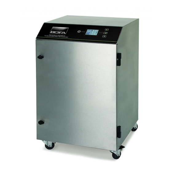
- Page 3 Overview USB Port Control Panel Combined Filter Company Key Lock Door Branding Catch LCD Display Combined Filter Lever Filter Stops Door Catches Lockable Castors Pre Filter...
- Page 4 Overview Compressor Connection (Optional) Main Isolation Switch Motor Cooling In/Out Signal Cable Inlet Mains Inlet Exhaust Outlet Air Inlet...
- Page 5 Overview...
-
Page 6: Safety Instructions
Please note that the media within the gas filter fitted in the Caution AD500 iQ is capable of adsorbing a wide range of organic compounds. However, it is the responsibility of the user to Refers to a possibly harmful situation. If not avoided,... - Page 7 Safety Instructions Serial Number Label Location: Top right on the right hand side panel. Warning and Information labels Meaning: This label contains a variety of information about The following listing details labels used on your AD 500 iQ the extraction unit, including. unit.
-
Page 8: Before Installation
Ensure that 500 mm space is available around any vented Before installation panels on the extractor to ensure adequate airflow. 3. With the unit in position lock the 2 front castors. Inner transit packaging removal & unit placement Before installation, check the extraction unit for damage. All packaging must be removed before the unit is connected to the power supply. - Page 9 Installation Enclosures The AD500 iQ has been designed to remove and filter fume The extraction hose and nozzle can be attached to the containing potentially hazardous particulate and gases enclosure surrounding the marking zone provided that the generated during manufacturing processes. Such hazardous extraction point is within 50-75mm of the marking point.
- Page 10 The supply cord should only be replaced by a BOFA engineer as an electrical safety test may be required after replacement. The iQ system MUST be connected to a properly earthed outlet.
- Page 11 The extractor will need to be turned on and be out of Installation standby mode (See section for turning the extractor on) in order for this feature to operate. Volt free input This configuration requires the Black & Red cores of the signal cable (see section for location) to be connected together, in order to start the extractor.
- Page 12 Installation Separated Signal With this configuration the Filter blocked & System fail signals will be separated to give 2 individual signals. When the filters become blocked the connection between the Green & White cables will become “Open” If the iQ system develops a fault (Refer to section Filter Blocked / System Fail Signal Troubleshooting &...
- Page 13 Installation Optional Added Feature: Door and Pre Filter Interlock With this option the iQ system will not function if the front door has been left open. There is a switch located on the internal cam shelf next to the combined filter handle. To enable the iQ system to function, the front door must be closed and the latches secured.
- Page 14 Changing the display units Operation The Airflow and temperature readings can be displayed in 2 ways. Temperature displayed as Airflow displayed as m 2. Temperature displayed as Airflow displayed as CFM Turning extraction unit On There are 2 stages to powering up your iQ extraction unit. The display value can be changed by pressing the “Enter”...
- Page 15 Operation Setting the desired airflow The iQ system features automatic flow control. This enables the user to set the required airflow rate, then over time as the filters begin to block the motor will automatically begin to increase in speed to compensate for any loss in performance caused by the added restriction of the partially blocked filters.
- Page 16 Operation Airflow Auto Adjust (first installation only) When first setting the airflow on your new extraction unit the iQ will detect if the desired airflow is achievable with the installation that has been connected to the extraction unit. If the installation is causing too much restriction for the desired airflow to be reached, the Auto Adjust feature will be activated.
- Page 17 Maintenance Pre Filter blocking Combined Filter Blocking Maintenance UK It is a legal requirement, under regulation 9 of the COSHH regulations that all local exhaust ventilation systems are thoroughly examined and tested at least once every 14 months (typically carried out annually). The approved code of practice recommends that a visual check should be carried out at least once a week.
- Page 18 To remove and replace the Combined filter follow Maintenance the procedure detailed below. Warning The combined filter is very heavy (Over 40Kgs) therefore the procedure below must be carried out by 2 people lifting together. Isolate the electrical supply to the extractor Pre Filter Replacement 2.
- Page 19 iQ System Display Hose blocked alarm The iQ system features a 2 stage Hose blocked alarm. • Partial hose blockage • Full hose blockage Partial hose blocked alarm This alarm will become active when the iQ system detects a iQ Display Features part blockage in the installation.
- Page 20 If the VOC level in the exhaust exceeds the PPM (Parts per million) level pre-set at BOFA then the Gas alarm will be triggered and display the Gas icon as shown below.
- Page 21 iQ System Display USB Connectivity The iQ system is equipped with a USB drive, that operates as a 2 way device, as detailed below. • Duplicating iQ settings • Download iQ Data Duplicating iQ settings (USB Upload) This USB upload feature has been designed for customers that have multiple extractors and specific set of parameters that they wish to duplicate across their iQ extraction units.
- Page 22 iQ System Display Download iQ Data (USB Download) With this feature the customer is able to download all stored data within the iQ system, this information can then be used to keep records of how your iQ system is performing, this is also very beneficial for the technical team when diagnosing issues with the extraction system.
- Page 23 BOFA helpline. Combined filter % blockage The display on the extractor will show the combined filter...
-
Page 24: Troubleshooting
In the event of an error code being displayed please contact Motor Failure your local representative or BOFA who will be able to If the extraction unit develops a fault relating to the motor diagnose the fault and advise on the most efficient solution. -
Page 25: Replacement Parts
To maintain performance it is important that the filters are The thresholds for these replaced with identical BOFA filters. To re-order please refer risks can then be compared to the Filter number printed on the filter installed in your with the amount of material extraction unit. - Page 26 System Specifications Unit: AD 500 IQ Capacity: 550m /h (323cfm) Weight: 142.7Kg (314.5lbs) Motor: Centrifugal Fan Output: 1100w Voltage & Current: 115V/14.8A 230V/9.5A Hertz: 50/60Hz Noise Level: Below 60dB (A) (at typical operating speed) Maximum Altitude – 2000m Size: Metric Imperial (mm) (inches)
-
Page 27: Contact Information
Contact Information BOFA Headquarters 21-22 Balena Close Creekmoor industrial Estate Poole Dorset BH17 7DX Phone: +44 (0) 1202 699444 BOFA Americas 303 S.Madison Street Staunton Illnois 62088 Phone: 001 (618) 205-5007...
Need help?
Do you have a question about the AD500 iQ and is the answer not in the manual?
Questions and answers