Advertisement
Advertisement
Table of Contents

Related Manuals for Bofa V250


Summary of Contents for Bofa V250
- Page 1 V250 V1 Feb 15...
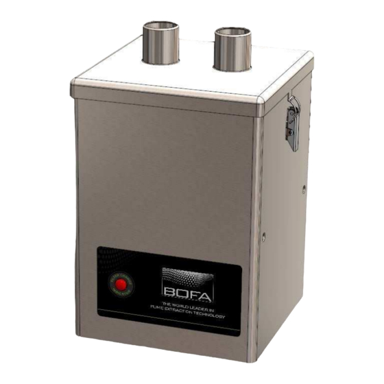
- Page 3 Overview Clips Air Inlets Filter Condition Light Company Branding...
- Page 4 Overview Air Outlet/Motor Cooling Fuse Compartment Mains Inlet Main Isolation Switch...
-
Page 5: Safety Instructions
Dangers to eyes, breathing and skin to within this manual. Once used, the filter within the V250 system may contain a mixture of particulates, some of which may be sub-micron size. When the used filters are moved it may agitate some of... - Page 6 Location: Next to mains inlet. Warning and Information labels Meaning: This label contains a variety of information about The following listing details labels used on your V250 the extraction unit, including. extraction unit. • Company name, Address & Contact number Goggles, Gloves &...
-
Page 7: Before Installation
Before installation Packaging Removal & Unit Placement Before installation, check the extraction unit for damage. All packaging must be removed before the unit is connected to the power supply. Please read all instructions in this manual before using this extractor. 1. -
Page 8: Installation
The supply cord should only be replaced by a BOFA engineer as an electrical safety test may be required after replacement. The extraction unit MUST be connected to a properly earthed outlet. -
Page 9: Operation
Turning extraction unit On unit maintains good airflow. The V250 features a fused IEC inlet for the mains cable as To increase the airflow, press and hold the ‘up’ arrow. The well as a main isolation switch. The unit can be powered on... -
Page 10: Maintenance
no longer removes fume efficiently. Maintenance All filters are tested to BS3928. A certificate of conformity for each filter is available on request. It is recommended that a spare set of filters are kept on site to avoid prolonged unit unavailability. Part numbers for replacement filters can be found on the filters fitted in your system. - Page 11 Maintenance Filter Replacement The V250 will alert the user when its filters needs to be replaced. When the filter becomes full the red ‘Filter Indicator ‘ light next on the left side of the label will glow. To remove and replace the combined filter follow the procedure detailed below.
-
Page 12: Replacement Parts
Deposit Comment The V250 contains a pre filter and combined filter. These Listing* should be replaced when instructed to do so by the V250 15 02 03 Can be disposed of as non- system (see section for replacing the filters) Hazardous hazardous waste. -
Page 13: System Specifications
System Specifications Unit: V250 Capacity: 180 m³h (106 CFM) Weight: 10kg (22lbs) Motor: Centrifugal Fan Output: 140w Electrical supply: 115/230V Hertz: 50/60Hz Full Load Current: 230v: 1A 115v:1.2A Noise Level: Below 55db (at typical operating speed) Size: Metric Imperial (mm) -
Page 14: Contact Information
Contact Information BOFA Headquarters 21-22 Balena Close Creekmoor industrial Estate Poole Dorset BH17 7DX Phone: +44 (0) 1202 699444 BOFA Americas 303 S.Madison Street Staunton Illnois 62088 Phone: 001 (618) 205-5007...
Need help?
Do you have a question about the V250 and is the answer not in the manual?
Questions and answers