Table of Contents
Advertisement
Advertisement
Table of Contents

Related Manuals for THORLABS APD430 Series


Summary of Contents for THORLABS APD430 Series
- Page 1 Adjustable Gain Avalanche Photodetectors APD430x Operation Manual 2015...
- Page 2 Version: Date: 09-Sep-2015 Copyright © 2015 Thorlabs...
-
Page 3: Table Of Contents
5.4 Typical Spectral Noise 5.5 Drawings 5.6 Fiber Coupling onto Small Detector Area 5.7 Certifications and Compliances 5.8 Warranty 5.9 Copyright and Exclusion of Reliability 5.10 Thorlabs 'End of Life' Policy 5.11 List of Acronyms and References 5.12 Thorlabs Worldwide Contacts... -
Page 4: Foreword
Paragraphs preceeded by this symbol explain hazards that could damage the instrument and the connected equipment or may cause loss of data. Note This manual also contains "NOTES" and "HINTS" written in this form. Please read these advices carefully! © 2015 Thorlabs... -
Page 5: General Information
High Voltage - do not remove covers! Refer servicing to qualified personnel! Only with written consent from Thorlabs may changes to single components be made or components not supplied by Thorlabs be used. This precision device is only serviceable if properly packed into the complete original packaging. -
Page 6: Ordering Codes And Accessories
APD, 900 - 1700 nm, 8-32 mounting holes APD430C/M Temperature Compensated, Adjustable Gain Avalanche Photodetector, InGaAs APD, 900 - 1700 nm, M4 mounting holes AC-coupled versions as well as open detector versions (detector cover glass removed) of each model can be ordered on request. © 2015 Thorlabs... -
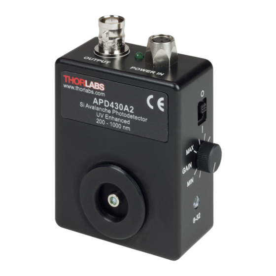
Page 7: Getting Started
Note If you want to use your own power supply, you can ask Thorlabs for an appropriate power connector cable. · Carefully unpack the unit and accessories. If any damage is noticed, do not use the unit. -
Page 8: Operating Instruction
An open beam should be carefully aligned to the detector. Additional focusing lenses can be easily attached to the Avalanche Photodetectors. The housing is compatible with any number of Thorlabs 1” and ½” threaded accessories. This allows convenient mounting of external optics, filters, apertures or fiber adapters. -
Page 9: Electrical Output
Attention The optical damage threshold is 1 mW. Exceeding this value will permanently destroy the Avalanche Photodetector! 3.1.2 Electrical Output Thorlabs APD430x Avalanche Photodetectors deliver an OUTPUT voltage, which is a function Â(l) of incident light power , detector's responsivity... -
Page 10: Mounting
Thorlabs 1” and ½” threaded accessories. This allows convenient mounting of external optics, filters, apertures or fiber adapters, as well as providing an easy mounting mechanism using the Thorlabs cage assembly accessories. -
Page 11: Operation
· Turn the power switch to O when you are finished the measurements. Note Avoid saturating the amplifier! Therefore, make sure that the optical input power does not exceed the saturation power level listed in specifications Attention Exceeding the optical damage threshold input power will permanently destroy the detector! © 2015 Thorlabs... -
Page 12: Recommendations
Another critical point can be electrostatic coupling of electrical noise associated with ground loops. In most cases an electrically isolated post (see Thorlabs parts TRE or TRE/M) will suppress electrical noise coupling. You should always try to identify the electrical noise sources and increase the distance to the Avalanche Photodetector. -
Page 13: Maintenance And Service
The unit does not need a regular maintenance by the user. It does not contain any modules and/or components that could be repaired by the user himself. If a malfunction occurs, please contact Thorlabs for return instructions. Do not remove covers! High voltage! © 2015 Thorlabs... -
Page 14: Appendix
Weight < 0.1 kg ) Ambient temperature within (23 ± 5)°C ) At maximum gain setting. ) Non-condensing All technical data are valid at (23 ± 5) °C and (45 ± 15) % rel. humidity (non condensing) © 2015 Thorlabs... -
Page 15: Typical Detector Responsivity Curves
5 Appendix 5.2 Typical Detector Responsivity Curves Typical Detector Responsivity APD430A; M = 100 Typical Detector Responsivity APD430A2; M = 100 © 2015 Thorlabs... - Page 16 APD430x Typical Detector Responsivity APD430C; M = 20 © 2015 Thorlabs...
-
Page 17: Typical Output Frequency Response
For this measurement a test signal, generated by an optical transmitter, was fiber-coupled to the Avalanche Photodetector. The OUTPUT frequency response was measured using a optical network analyzer. Typical Output Frequency Response APD430A Typical Output Frequency Response APD430A2 © 2015 Thorlabs... - Page 18 APD430x Typical Output Frequency Response APD430C © 2015 Thorlabs...
-
Page 19: Typical Spectral Noise
10 kHz, video bandwidth 10 kHz). The optical input of the detector was blocked. The black curve ("Reference") was measured with the same setup and the detector switched off , i.e., it represents the measurement system’s noise floor. Typical Spectral Noise APD430A Typical Spectral Noise APD430A2 © 2015 Thorlabs... - Page 20 APD430x Typical Spectral Noise APD430C © 2015 Thorlabs...
-
Page 21: Drawings
5 Appendix 5.5 Drawings Distance between the surface of the active detector area and the front of the flange Distance A Type A2 Type C Type (2.2 ± 0.3) mm (2.2 ± 0.3) mm (2.1 ± 0.3) mm © 2015 Thorlabs... - Page 22 APD430x Dimensions APD430X Series (Imperial) © 2015 Thorlabs...
- Page 23 5 Appendix Dimensions APD430X/M Series (Metric) © 2015 Thorlabs...
-
Page 24: Fiber Coupling Onto Small Detector Area
The beam out of the fiber is collimated (transferred into a nearly parallel beam) and afterwards focused by the aspheric lens onto the detector. The X-Y translation mount allows the focused beam to be aligned with the center of the sensor. © 2015 Thorlabs... -
Page 25: Certifications And Compliances
5 Appendix 5.7 Certifications and Compliances © 2015 Thorlabs... -
Page 26: Warranty
Thorlabs warrants material and production of the APD430x for a period of 24 months starting with the date of shipment. During this warranty period Thorlabs will see to defaults by repair or by exchange if these are entitled to warranty. -
Page 27: Copyright And Exclusion Of Reliability
User Manual. Should you require further information on this product, or encounter specific problems that are not discussed in sufficient detail in the User Manual, please contact your local Thorlabs dealer or system installer. -
Page 28: Thorlabs 'End Of Life' Policy
Waste treatment on your own responsibility If you do not return an “end of life” unit to Thorlabs, you must hand it to a company specialized in waste recovery. Do not dispose of the unit in a litter bin or at a public waste disposal site. -
Page 29: List Of Acronyms And References
5 Appendix 5.11 List of Acronyms and References Acronyms Alternating Current Avalanche Photo Diode Continuous Wave Direct Current Light Emitting Diode Noise Equivalent Power Radio Frequencies Silicon Signal-to-Noise Ratio Ultraviolet References Hamamatsu - Technical Information SD-28 © 2015 Thorlabs... -
Page 30: Thorlabs Worldwide Contacts
Email: europe@thorlabs.com Email: scandinavia@thorlabs.com France Brazil Thorlabs SAS Thorlabs Vendas de Fotônicos Ltda. 109, rue des Côtes Rua Riachuelo, 171 78600 Maisons-Laffitte São Carlos, SP 13560-110 France Brazil Tel: +33-970 444 844 Tel: +55-16-3413 7062 Fax: +33-811 38 17 48 Fax: +55-16-3413 7064 www.thorlabs.com...
Need help?
Do you have a question about the APD430 Series and is the answer not in the manual?
Questions and answers