Table of Contents
Advertisement
Advertisement
Table of Contents

Related Manuals for THORLABS DET10A


Summary of Contents for THORLABS DET10A
- Page 1 DET10A(/M) Si Biased Detector User Guide...
-
Page 2: Table Of Contents
7.1. Response Curve ............ 13 7.2. Mechanical Drawing .......... 14 Chapter 8 Certificate of Conformance ..........15 Chapter 9 Regulatory ................ 16 9.1. Waste Treatment is Your Own Responsibility .... 16 9.2. Ecological Background .......... 16 Chapter 10 Thorlabs Worldwide Contacts ........17 ... -
Page 3: Chapter 1 Warning Symbol Definitions
Si Biased Detector Chapter 1: Warning Symbol Definitions Chapter 1 Warning Symbol Definitions Below is a list of warning symbols you may encounter in this manual or on your device. Symbol Description Direct Current Alternating Current Both Direct and Alternating Current Earth Ground Terminal Protective Conductor Terminal Frame or chassis Terminal... -
Page 4: Chapter 2 Description
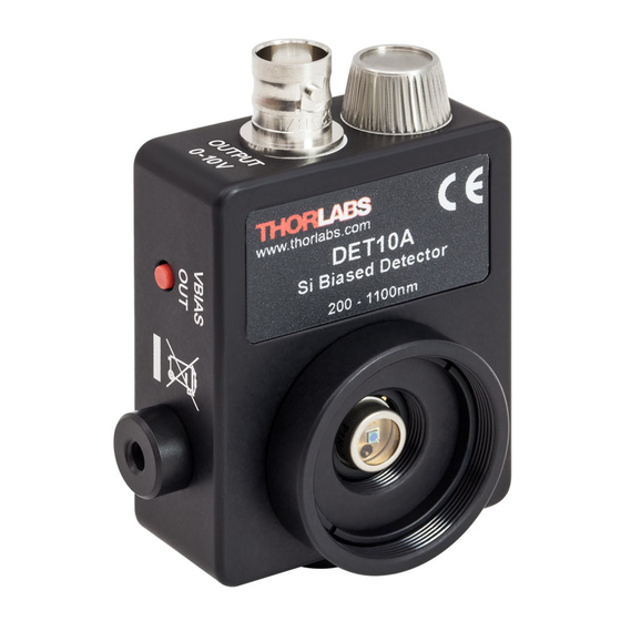
Chapter 2: Description Chapter 2 Description The Thorlabs DET10A(/M) is a biased, Silicon (Si) detector designed for detection of light signals ranging from 200 nm to 1100 nm. The unit comes complete with a photodiode and an internal 12 V bias battery enclosed in a rugged aluminum housing. -
Page 5: Chapter 3 Setup
Failure to do so may cause damage to the diode and or the fiber. An easy way to accomplish this is to install a SM1RR retaining ring [included with the DET10A(/M)] inside the 1" threaded coupler before installing the fiber adapter. -
Page 6: Chapter 4 Operation
Depicted in Figure 1 is a junction photodiode model with basic discrete components to help visualize the main characteristics and gain a better understanding of the operation of Thorlabs' photodiodes. Series... -
Page 7: Dark Current
Si Biased Detector Chapter 4: Operation Photoconductive In photoconductive mode, an external reverse bias is applied, which is the basis for our DET series detectors. The current measured through the circuit indicates illumination of the device; the measured output current is linearly proportional to the input optical power. -
Page 8: Junction Capacitance
Si Biased Detector Chapter 4: Operation The table below gives some advantages to each common type of detector material. Dark Sensitivity Material Current Speed (nm) Cost Silicon (Si) High 400 – 1000 Germanium (Ge) High 900 – 1600 Gallium Phosphide (GaP) High 150 –... -
Page 9: Terminating Resistance
Si Biased Detector Chapter 4: Operation 4.7. Terminating Resistance A load resistance is used to convert the generated photocurrent into a voltage ) for viewing on an oscilloscope: Depending on the type of the photodiode, load resistance can affect the response speed. -
Page 10: Battery Replacement
50 , 1050 4.11. Battery Replacement Thorlabs delivers each DET with an A23 12 V battery installed. This battery is readily available at most retail stores, as well as through Thorlabs. Please note that due to slight physical variations of the positive terminal from manufacturer to... -
Page 11: Chapter 5 Common Operating Circuits
Si Biased Detector Chapter 5: Common Operating Circuits Chapter 5 Common Operating Circuits RC Filter External Protection Diode Photodetector Resistor V Bias Voltage Regulator 1 kΩ On/Off Switch LOAD Capacitor 0.1 µF Battery Figure 2 Basic DET Circuit The DET Series Detectors are designed according the circuit depicted above. The detector is reverse biased to produce a linear response with applied input light. - Page 12 Si Biased Detector Chapter 5: Common Operating Circuits One can also use a photodetector with an amplifier for the purpose of achieving high gain. The user can choose whether to operate in Photovoltaic of Photoconductive modes. There are a few benefits of choosing this active circuit: ...
-
Page 13: Chapter 6 Troubleshooting
Si Biased Detector Chapter 6: Troubleshooting Chapter 6 Troubleshooting Problem Suggested Solutions There is no signal response. Verify that the power is switched on and all connections are secure. Verify the proper terminating resistor is installed if using a Voltage measurement device. Verify that the optical signal wavelength is within the specified wavelength range. -
Page 14: Chapter 7 Specifications
Si Biased Detector Chapter 7: Specifications Chapter 7 Specifications All measurements are performed at 25 °C ambient temperature unless stated otherwise. Electrical Specifications Detector Silicon Active Area Ø1.0 mm (0.8 mm Wavelength Range λ 200 to 1100 nm Peak Wavelength λ... -
Page 15: Response Curve
Si Biased Detector Chapter 7: Specifications 7.1. Response Curve Spectral Response 0.50 0.40 0.30 0.20 0.10 0.00 1000 1100 Wavelength (nm) Rev I, September 28, 2017 Page 13... -
Page 16: Mechanical Drawing
Si Biased Detector Chapter 7: Specifications 7.2. Mechanical Drawing Visit the web for a more detailed mechanical drawing. 48.0 mm 26.2 mm 1.89 in 1.03 in 43.2 mm #8-32 x 0.25" Thread 1.70 in (M4 x 6.35mm for -EC) 16.2 mm 0.64 in Power Switch 53.3 mm... -
Page 17: Chapter 8 Certificate Of Conformance
Si Biased Detector Chapter 8: Certificate of Conformance Chapter 8 Certificate of Conformance Rev I, September 28, 2017 Page 15... -
Page 18: Chapter 9 Regulatory
9.1. Waste Treatment is Your Own Responsibility If you do not return an “end of life” unit to Thorlabs, you must hand it to a company specialized in waste recovery. Do not dispose of the unit in a litter bin or at a public waste disposal site. -
Page 19: Chapter 10 Thorlabs Worldwide Contacts
Si Biased Detector Chapter 10: Thorlabs Worldwide Contacts Chapter 10 Thorlabs Worldwide Contacts USA, Canada, and South America UK and Ireland Thorlabs, Inc. Thorlabs Ltd. 56 Sparta Avenue 1 Saint Thomas Place, Ely Newton, NJ 07860 Cambridgeshire CB7 4EX Great Britain... - Page 20 www.thorlabs.com...
Need help?
Do you have a question about the DET10A and is the answer not in the manual?
Questions and answers