Libelium Waspmote Technical Manual
Hide thumbs
Also See for Waspmote:
- Technical manual (147 pages) ,
- Manual (39 pages) ,
- Quick start manual (27 pages)

Related Manuals for Libelium Waspmote


Summary of Contents for Libelium Waspmote
- Page 1 Waspmote Technical Guide...
-
Page 2: Table Of Contents
1. Waspmote Kit ............................6 1.1. General and safety information ..............................6 1.2. Conditions of use ..................................7 1.3. Assembly ......................................9 2. Waspmote Plug & Sense! - Encapsulated Line ................. 14 2.1. Quick Overview ..................................14 2.1.1. Features ..................................14 2.1.2. Sensor Probes ................................14 2.1.3. - Page 3 6.2. Sleep mode ....................................53 6.3. Deep Sleep mode ..................................54 6.4. Hibernate mode ..................................54 7. Sensors ............................... 56 7.1. Sensors in Waspmote ................................56 7.1.1. Temperature .................................56 7.1.2. Accelerometer ................................57 7.2. Integration of new sensors ..............................61 7.3. Sensor Boards ..................................... 62 7.4.
- Page 4 Index 13. Bluetooth Pro ........................... 85 13.1. Technical specifications ................................ 85 13.2. Bluetooth module for device discovery ......................... 87 14. Bluetooth Low Energy ........................89 14.1. Technical specifications: ..............................89 15. GSM/GPRS ............................91 16. GPRS+GPS ............................93 17. 3G + GPRS ............................95 18.
- Page 5 27.2.2. How do they work together? ..........................144 27.2.2.1. Meshlium Storage Options ....................... 144 27.2.2.2. Meshlium Connection Options ....................... 144 27.2.3. Capturing and storing sensor data in Meshlium from a Waspmote sensor network ....145 27.2.4. Capturer logs ................................. 159 27.2.5. Sensors ..................................160 27.2.6.
-
Page 6: Waspmote Kit
1. Waspmote Kit 1.1. General and safety information • In this section, the term “Waspmote” encompasses both the Waspmote device itself and its modules and sensor boards. • Please read carefully through the document “General Conditions of Libelium Sale and Use”. -
Page 7: Conditions Of Use
As specified in the Warranty document, the client has 7 days from the day the order is received to detect any failure and report that to Libelium. Any other failure reported after these 7 days may not be considered under warranty. - Page 8 It is not reccommended to have the non-rechargeable batteries (13000, 26000, 52000 mA·h) connected to Waspmote when the USB cable is conneted too. The reason is, Waspmote will try to inject current in them if the USB is connected. This is dangerous for the good working of a non-rechargeable battery.
-
Page 9: Assembly
Waspmote Kit 1.3. Assembly Connect the antenna to the wireless module • • Place the wireless module in Waspmote Place the wireless module in Waspmote Gateway • v6.3... - Page 10 Waspmote Kit Connect the antenna in the GSM/GPRS module • • Place the GSM/GPRS module in Waspmote Place the SD card in Waspmote • -10- v6.3...
- Page 11 Waspmote Kit Connect the battery in Waspmote • Connect the sensor board • Switch it on • -11- v6.3...
- Page 12 Waspmote Kit Waspmote battery disconnection • Use the pick supplied by Libelium in order to disconnect Waspmote battery. Insert the pick on the slot of the battery connector and pull straight out. Do not pull the battery cables. -12- v6.3...
- Page 13 Waspmote Kit Battery handling instructions • In order to prevent from cable breaking, avoid leaving battery freely suspended. Use a nylon clamp in order to attach battery to Waspmote. -13- v6.3...
-
Page 14: Waspmote Plug & Sense! - Encapsulated Line
2. Waspmote Plug & Sense! - Encapsulated Line Waspmote is the original line in which developers have a total control over the hardware device. You can physically access to the board and connect new sensors or even embed it in your own products as an electronic sensor device. -
Page 15: Solar Powered
The external solar panel is mounted on a 45º holder which ensures the maximum performance of each outdoor installation. Figure: Waspmote Plug & Sense! powered by an external solar panel For the internal option, the solar panel is embedded on the front of the enclosure, perfect for use where space is a major challenge. -
Page 16: Programming The Nodes
Waspmote Plug & Sense! - Encapsulated Line Figure: Waspmote Plug & Sense! powered by an internal solar panel 2.1.4. Programming the Nodes Waspmote Plug & Sense! can be reprogrammed in two ways: The basic programming is done from the USB port. Just connect the USB to the specific external socket and then to the computer to upload the new firmware. -
Page 17: Radio Interfaces
Over the Air Programming is also possible once the node has been installed. With this technique you can reprogram wirelessly one or more Waspmote sensor nodes at the same time by using a laptop and the Waspmote Gateway. Figure: Typical OTAP process 2.1.5. -
Page 18: Program In Minutes
2.1.7. Data to the Cloud The Sensor data gathered by the Waspmote Plug & Sense! nodes is sent to the Cloud by Meshlium, the Gateway router specially designed to connect Waspmote sensor networks to the Internet via Ethernet, WiFi and 3G interfaces. -
Page 19: Models
This section describes each model configuration in detail, showing the sensors which can be used in each case and how to connect them to Waspmote. In many cases, the sensor sockets accept the connection of more than one sensor probe. See the compatibility table for each model configuration to choose the best probe combination for the application. -
Page 20: Smart Environment
Smart Environment model is designed to monitor environmental parameters such as temperature, humidity, atmospheric pressure and some types of gases. The main applications for this Waspmote Plug & Sense! configuration are city pollution measurement, emissions from farms and hatcheries, control of chemical and industrial processes, forest fires, etc. Sensors are calibrated for more accurate measurements. - Page 21 Waspmote Plug & Sense! - Encapsulated Line Sensor sockets are configured as shown in the figure below. Sensor probes allowed for each sensor socket Sensor Socket Parameter Reference Temperature 9203 Carbon monoxide - CO 9229 Methane - CH 9232 Ammonia – NH...
-
Page 22: Smart Environment Pro
The Smart Environment PRO model has been created as an evolution of Smart Environment. It enables the user to implement pollution, air quality, industrial, environmental or farming projects with high requirements in terms of high accuracy, reliability and measurement range as the sensors come calibrated from factory. Figure: Smart Environment PRO Waspmote Plug & Sense! model -22- v6.3... - Page 23 Waspmote Plug & Sense! - Encapsulated Line Sensor sockets are configured as shown in the figure below. Sensor probes allowed for each sensor socket Sensor Socket Parameter Reference Carbon Monoxide (CO) [Calibrated] 9371-P Carbon Dioxide (CO ) [Calibrated] 9372-P Oxygen (O...
-
Page 24: Smart Security
Waspmote Plug & Sense! - Encapsulated Line 2.1.8.3. Smart Security The main applications for this Waspmote Plug & Sense! configuration are perimeter access control, liquid presence detection and doors and windows openings. Figure: Smart Security Waspmote Plug & Sense! model Note: The probes attached in this photo could not match the final location. - Page 25 Waspmote Plug & Sense! - Encapsulated Line Sensor Sensor probes allowed for each sensor socket Socket Parameter Reference Temperature + Humidity (Sensirion) 9247 Liquid flow 9296, 9297, 9298 Presence - PIR 9212 Luminosity (LDR) 9205 Liquid level 9239, 9240, 9242...
-
Page 26: Smart Water
Waspmote Plug & Sense! - Encapsulated Line 2.1.8.4. Smart Water The Smart Water model has been conceived to facilitate the remote monitoring of the most relevant parameters related to water quality. With this platform you can measure more than 6 parameters, including the most relevant for water control such as dissolved oxygen, oxidation-reduction potential, pH, conductivity and temperature. - Page 27 Waspmote Plug & Sense! - Encapsulated Line Sensor sockets are configured as shown in the figure below. Sensor probes allowed for each sensor socket Sensor Socket Parameter Reference 9328 Oxidation-Reduction Potential (ORP) 9329 9328 Oxidation-Reduction Potential (ORP) 9329 Soil/Water Temperature...
-
Page 28: Smart Water Ions
The Smart Water line is complementary for these kinds of projects, enabling the control of parameters like turbidity, conductivity, oxidation-reduction potential and dissolved oxygen. Take a look to the Smart Water line in the previous section. Refer to Libelium website for more information. - Page 29 Waspmote Plug & Sense! - Encapsulated Line Single This variant includes a Single Junction Reference Probe, so it can read all the single type ion sensors. Sensor sockets are configured as shown in the table below. Sensor probes allowed for each sensor socket...
- Page 30 Waspmote Plug & Sense! - Encapsulated Line Double This variant includes a Double Junction Reference Probe, so it can read all the double type ion sensors. Sensor sockets are configured as shown in the table below. Sensor probes allowed for each sensor socket...
- Page 31 Waspmote Plug & Sense! - Encapsulated Line This special variant integrates extreme quality sensors, with better performance than the Single or Double lines. In this case, there is only one type of reference probe and up to 16 different ion parameters can be analyzed in 4 sockets.
-
Page 32: Smart Cities
2.1.8.6. Smart Cities The main applications for this Waspmote Plug & Sense! model are noise maps (monitor in real time the acoustic levels in the streets of a city), air quality, waste management, structural health, smart lighting, etc. Refer to... - Page 33 Waspmote Plug & Sense! - Encapsulated Line Sensor sockets are configured as shown in the figure below. Sensor Sensor probes allowed for each sensor socket Socket Parameter Reference Temperature 9203 Soil temperature 86949* Ultrasound (distance measurement) 9246 Humidity 9204 Ultrasound (distance measurement)
-
Page 34: Smart Parking
Waspmote Plug & Sense! - Encapsulated Line 2.1.8.7. Smart Parking The Plug & Sense! Smart Parking node allows to detect available parking spots by placing the node on the pavement. It works with a magnetic sensor which detects when a vehicle is present or not. -
Page 35: Smart Agriculture
(Sensirion), solar visible radiation, wind speed and direction, rainfall, atmospheric pressure, etc. The main applications for this Waspmote Plug & Sense! model are precision agriculture, irrigation systems, greenhouses, weather stations, etc. Refer to Libelium website for more information. - Page 36 Waspmote Plug & Sense! - Encapsulated Line Normal Sensor sockets are configured as shown in the figure below. Sensor Sensor probes allowed for each sensor socket Socket Parameter Reference Humidity + Temperature (Sensirion) 9247 Atmospheric pressure 9250 Soil temperature 86949*...
-
Page 37: Ambient Control
2.1.8.9. Ambient Control This model is designed to monitor main environment parameters in an easy way. Only three sensor probes are allowed for this model, as shown in next table. Figure: Ambient Control Waspmote Plug & Sense! model -37- v6.3... - Page 38 Waspmote Plug & Sense! - Encapsulated Line Sensor sockets are configured as it is shown in figure below. Sensor Sensor probes allowed for each sensor socket Socket Parameter Reference Humidity + Temperature (Sensirion) 9247 Luminosity (LDR) 9205 Luminosity (Luxes accuracy)
-
Page 39: Radiation Control
The main application for this Waspmote Plug & Sense! configuration is to measure radiation levels using a Geiger sensor. For this model, the Geiger tube is already included inside Waspmote, so the user does not have to connect any sensor probe to the enclosure. -
Page 40: Hardware
3. Hardware 3.1. Modular Architecture Waspmote is based on a modular architecture. The idea is to integrate only the modules needed in each device. These modules can be changed and expanded according to needs. The modules available for integration in Waspmote are categorized in: ZigBee/802.15.4 XBee modules (2.4GHz, 868MHz, 900MHz) -
Page 41: Block Diagram
Hardware Main Waspmote components – Bottom side 3.3. Block Diagram Data signals: Figure: Waspmote block diagrams – Data signals -41- v6.3... -
Page 42: Electrical Data
Hardware Power signals: Figure: Waspmote block diagrams – Power signals 3.4. Electrical Data Operational values: Minimum operational battery voltage 3.3 V Maximum operational battery voltage 4.2V USB charging voltage Solar panel charging voltage 6 - 12 V Battery charging current from USB 100 mA (max) -
Page 43: I/O
Hardware 3.5. I/O Waspmote can communicate with other external devices through the using different input/output ports. Figure: I/O connectors in Waspmote Sensor connector: ANALOG 3V3 SENSOR POWER DIGITAL 8 DIGITAL 6 DIGITAL 7 DIGITAL 4 DIGITAL 5 DIGITAL 2 DIGITAL 3... -
Page 44: Analog
=> val = analogRead(ANALOG1); 3.5.2. Digital Waspmote has digital pins which can be configured as input or output depending on the needs of the application. The voltage values corresponding to the different digital values would be: 0V for logic 0 3.3V for logic 1... -
Page 45: Uart
For USB communication, microcontroller’s UART0 is used. The FT232RL chip carries out the conversion to USB standard. 3.6. Real Time Clock - RTC Waspmote has a built in Real Time Clock – RTC, which keeps it informed of the time. This allows Waspmote to be programmed to perform time-related actions such as: “Sleep for 1h 20 min and 15sec, then wake up and perform the following action”... - Page 46 The RTC is responsible for waking Waspmote up from 2 of the maximum energy saving modes Deep Sleep and Hibernate. This makes possible for the Waspmote to use its battery just to power the RTC in sleep modes. The RTC controls when it has to wake Waspmote up and perform a particular action.
-
Page 47: Leds
Charging battery LED indicator A red LED indicating that there is a battery connected in Waspmote which is being charged, the charging can be done through a mini USB cable or through a solar panel connected to Waspmote. Once the battery is completely charged, the LED switches off automatically. -
Page 48: Architecture And System
To store values permanently, it is necessary to use the microcontroller’s EEPROM (4KB) non-volatile memory. EEPROM addresses from 0 to 1023 are used by Waspmote to save important data, so they must not be over-written. Thus, the available storage addresses go from 1024 to 4095. Another option is to use of the high capacity 2GB SD card. -
Page 49: Timers
4.2. Timers Waspmote uses a quartz oscillator which works at a frequency of 14.7456 MHz as a system clock. In this way, every 125ns the microcontroller runs a low level (machine language) instruction. It must be taken into account that each line of C++ code of a program compiled by Waspmote includes several instructions in machine language. -
Page 50: Interruptions
XBee module (Digimesh protocol only): Digimesh protocol allows the XBee to set cyclic sleep modes which can interrupt Waspmote each time the module wakes up. This permits to set up cyclic sleep networks. So, Digimesh XBees can wake up when certain internal timeout expires (however not when other node sends frames). - Page 51 This way, when Waspmote starts, it tests if it is a normal start or if it is an start from the Hibernate mode.
-
Page 52: Energy System
Note: The sleep mode for XBee is not a very useful feature, since the advised action is to switch XBee off after transmission. If the user puts XBee in sleep mode and also switches Waspmote to sleep or deepsleep, and if the SD card is plugged, there will be an excessive power consumption: 220 μA or more (instead of the expected 110 μA). -
Page 53: Sleep Mode
In this mode the microcontroller stops executing the main program. The program stack where all the variables and log values are stored keep their value, so when Waspmote returns to ON mode, the next instruction is executed and the variable values are maintained. -
Page 54: Deep Sleep Mode
In this mode the microcontroller stops executing the main program. The program stack where all the variables and log values are stored keep their value, so when Waspmote returns to ON mode, the next instruction is executed and the variable values are maintained. - Page 55 Once the “Hibernate switch” is off, the green led must blink to indicate the program is running. The following example would set Waspmote in the Hibernate mode for 2 days, 1 hour and 30 minutes. The microcontroller would be switched off waiting for the RTC to switch the device on again with a synchronous interruption.
-
Page 56: Sensors
7.1. Sensors in Waspmote 7.1.1. Temperature The Waspmote RTC (DS3231SN from Maxim) has a built in internal temperature sensor which it uses to recalibrate itself. Waspmote can access the value of this sensor through the I2C bus. Figure: Temperature sensor in the RTC Obtaining the temperature: RTC.getTemperature();... -
Page 57: Accelerometer
Sensors 7.1.2. Accelerometer Waspmote has a built in acceleration sensor LIS3331LDH STMicroelectronics which informs the mote of acceleration variations experienced on each one of the 3 axes (X,Y,Z). The integration of this sensor allows the measurement of acceleration on the 3 axes (X,Y,Z), establishing 4 kind of events: Free Fall, inertial wake up, 6D movement and 6D position which are explained in the Interruptions Programming Guide. - Page 58 Sensors This accelerometer has an auto-test capability that allows the user to check the functioning of the sensor in the final application. Its operational temperature range is between -40ºC and +85ºC. The accelerometer communicates with the microcontroller through the I2C interface. The pins that are used for this task are the SCL pin and the SDA pin, as well as another INT pin to generate the interruptions.
- Page 59 Sensors Vibration: Acceleration: Free fall: -59- v6.3...
- Page 60 More information about interruptions generated by the accelerometer can be found in the chapter “Interruptions” and in the Interruptions Programming Guide. Related API libraries: WaspACC.h, WaspACC.cpp All information about their programming and operation can be found in the document: Accelerometer Programming Guide. All the documentation is located in the Development section in the Libelium website. -60- v6.3...
-
Page 61: Integration Of New Sensors
(UART) inputs and outputs, connection to the two lines of the (I2C) SCL and SDA Inter-Integrated Circuit bus, and connection to inputs for high level and low level interrupt. An image of the Waspmote output connectors can be seen in the section of the manual on “Inputs/Outputs”. -
Page 62: Sensor Boards
Connection between these and the mote takes place pin to pin using the two 2x11 and 1x12 connectors mentioned in the section “Hardware” → I/O. Currently, Waspmote has eight integration boards:... - Page 63 Sensors EVENTS APPLICATIONS SENSORS • Security • Pressure/Weight Hall effect (doors and windows), person • Hall Effect detection PIR • Temperature (+/-) • Liquid Presence • Emergencies Presence detection and water level • Liquid Level sensors, temperature • Liquid flow •...
- Page 64 Sensors SMART CITIES APPLICATIONS SENSORS • Noise maps • Microphone (dBA) Monitor in real time the acoustic • Crack propagation gauge levels in the streets of a city • Linear displacement • Dust • Structural health monitoring Crack propagation • Ultrasound (distance measurement) •...
- Page 65 APPLICATIONS • Prepared for the integration of any • Pad Area kind of sensor. • Integrated Circuit Area • Analog-to-Digital Converter (16b) It is possible to find more detailed information in the manual for each board at: http://www.libelium.com/development/waspmote/documentation -65- v6.3...
-
Page 66: Power
In the sensor connector there are also several power pins, specifically GND, SENSOR POWER and 5V SENSOR POWER. • SENSOR POWER: 3.3V power voltage (200 mA maximum) which is controlled from the Waspmote execution code. 5V SENSOR POWER: 5V power voltage (200 mA maximum) which is controlled from the Waspmote execution code. • -66-... -
Page 67: 4/Zigbee
802.15.4/ZigBee 8. 802.15.4/ZigBee Waspmote integrates the Digi XBee modules for communication in the ISM (Industrial Scientific Medical) bands. These modules communicate with the microcontroller using the UART_0 and UART_1 at 115200bps. There are 4 possible XBee modules distributed by Libelium for integration in Waspmote. - Page 68 Development section of the Libelium website, specifically in the document: “Security in 802.15.4 and ZigBee networks” The classic topology of this type of network is a star topology, as the nodes establish point to point connections with brother nodes through the use of parameters such as the MAC or network address.
- Page 69 Figure: XBee-PRO TX Power Related API libraries: WaspXBeeCore.h, WaspXBeeCore.cpp, WaspXBee802.h, WaspXBee802.cpp All information about their programming and operation can be found in the document: 802.15.4 Networking Guide. All the documentation is located in the Development section in the Libelium website. -69- v6.3...
-
Page 70: Xbee - Zigbee
802.15.4/ZigBee 8.2. XBee - ZigBee Module Frequency Transmission Power Sensitivity Number of channels Distance XBee-ZB-PRO 2,40 – 2,70GHz 50mW -102dBm 7000m Figure: XBee ZigBee PRO As ZigBee is supported in the IEEE 802.15.5 link layer, it uses the same channels as described in the previous section, with the peculiarity that the XBee-ZB-PRO model limits the number of channels to 13. - Page 71 Regarding the “Energy” section, the transmission power cannot be adjusted, because it is always set to 17 dBm Related API libraries: WaspXBeeCore.h, WaspXBeeCore.cpp, WaspXBeeZB.h, WaspXBeeZB.cpp All information about their programming and operation can be found in the document: ZigBee Networking Guide. All the documentation is located in the Development section in the Libelium website. -71- v6.3...
-
Page 72: Xbee - 868
802.15.4/ZigBee 8.3. XBee - 868 Module Frequency Transmission Power Sensitivity Channels Distance XBee 868 869,4 – 869,65MHz 315mW -112dBm 12km Figure: XBee 868 Note: The XBee 868 MHz module is provided with 4.5dBi antenna, which enables maximum range. The frequency used is the 869MHz band (Europe), using 1 single channel. The use of this module is only allowed in Europe. In the chapter “Certifications”, more information can be obtained about the Certifications. - Page 73 Figure: XBee TX Power Related API libraries: WaspXBeeCore.h, WaspXBeeCore.cpp, WaspXBee868.h, WaspXBee868.cpp All information about their programming and operation can be found in the document: 868MHz Networking Guide. All the documentation is located in the Development section in the Libelium website. -73- v6.3...
-
Page 74: Xbee - 900
802.15.4/ZigBee 8.4. XBee - 900 Module Frequency Tx Power Sensitivity Channels Distance XBee 900 902-928MHz 50mW -100dBm 10km Figure: XBee 900MHz Note: The XBee 868 MHz module is provided with 4.5dBi antenna, which enables maximum range. The frequency used is the 900MHz band, using 12 channels with a bandw idth of 2.16MHz per channel and a transmission rate of 156.25kbps. -
Page 75: Xbee-Digimesh
All information about their programming and operation can be found in the document: 900MHz Networking Guide. All the documentation is located in the Development section in the Libelium website. 8.5. XBee-DigiMesh The XBee-802.15.4 and XBee-900 modules can use an optional firmware (DigiMesh) so that they can create mesh networks instead of the usual point to point topology. - Page 76 Related API libraries: WaspXBeeCore.h, WaspXBeeCore.cpp, WaspXBeeDM.h, WaspXBeeDM.cpp All information about their programming and operation can be found in the document: DigiMesh Networking Guide. All the documentation is located in the Development section in the Libelium website. -76- v6.3...
-
Page 77: Lorawan
LoRaWAN 9. LoRaWAN LoRaWAN is a Low Power Wide Area Network (LPWAN) specification intended for wireless battery operated devices in regional, national or global network. LoRaWAN target key requirements of Internet of things such as secure bi-directional communication, mobility and localization services. This standard will provide seamless interoperability among smart Things without the need of complex local installations and gives back the freedom to the user, developer, businesses enabling the role out of Internet of Things. -
Page 78: Lora
Figure: LoRa module • Topology: Star Receiver/Central node: Meshlium LoRa, special Gateway LoRa (SPI) or another Waspmote or Plug & Sense! unit • Note: The XBee 868 MHz module is provided with 4.5dBi antenna, which enables maximum range. This is the radio with the best range performance, thanks to the excellent receiver sensitivity that the LoRa™ technology offers. - Page 79 LoRa Figure: Channel frequencies in the 868MHz band Figure: Channel frequencies in the 900MHz band -79- v6.3...
-
Page 80: Rssi
LoRa Encryption is implemented in the application level, thanks to the Waspmote’s AES library. The payload inside the wireless packet is encrypted so only nodes knowing the key can read the content. The encryption activation is as simple as running one of our LoRa with AES encryption examples. -
Page 81: Sigfox
Sigfox 11. Sigfox Sigfox is a private company that aims to build a worldwide network especially designed for IoT devices. The network is cellular, with thousands of base stations deployed in each country. Sigfox technology offers very long ranges for low-power, battery- constrained nodes. -
Page 82: Wifi
The WiFi module for the Waspmote platform completes the current connectivity possibilities enabling the direct communication of the sensor nodes with any WiFi router in the market. As well as this, this radio allows Waspmote to send directly the information to any iPhone or Android Smartphones without the need of an intermediate router, what makes possible to create WiFi sensor networks anywhere using just Waspmote and a mobile device as all of them run with batteries. - Page 83 As pointed before, the WiFi module can join any standard WiFi router, however the connection may also be performed using Meshlium instead of a standard WiFi router. Meshlium is the multiprotocol router designed by Libelium which is specially recommended for outdoor applications as it is designed to resist the hardest conditions in real field deployments.
-
Page 84: When Is Recommended To Use Meshlium Instead A Standard Wifi Router
WiFi 12.1.2. When is recommended to use Meshlium instead a standard WiFi router? As pointed before, the WiFi module for Waspmote can connect to any standard WiFi router (“home oriented”) in the market. However when deploying sensor networks outdoors you need a robust machine capable of resist the hardest conditions of rain, wind, dust, etc. -
Page 85: Bluetooth Pro
Bluetooth Pro 13. Bluetooth Pro The Waspmote Bluetooth Pro module (or simply, Bluetooth) uses the same socket as the XBee does. This means you can change the XBee module for the Bluetooth module as they are pin to pin compatible. - Page 86 Bluetooth Pro Figure: Start topology Bluetooth uses 79 channels with a bandwidth of 1MHz per channel. In addition, Adaptive Frequency Hopping (AFH) is used to enhance the transmissions. Figure: Frequency channels in the 2.4GHz band Bluetooth modules have some important parameters for their configuration: MAC address: It is the unique identification number of the Bluetooth device.
-
Page 87: Bluetooth Module For Device Discovery
ZigBee and Bluetooth work in the 2.4GHz frequency band (2.400 - 2.480MHz), however, the Bluetooth radio integrated in Waspmote uses an algorithm called Adaptive Frequency Hopping (AFH) which improves the common algorithm used by Bluetooth (FHSS) and enables the Bluetooth radio to dynamically identify channels already in use by ZigBee and WiFi devices and to avoid them. - Page 88 No. The idea is to use this radio “as a sensor”. All the API functions developed are thought to detect as many Bluetooth devices as possible. In order to comunicate with other Bluetooth devices another module is available for the Waspmote platform. For further information read the chapter “Bluetooth”...
-
Page 89: Bluetooth Low Energy
Bluetooth Low Energy 14. Bluetooth Low Energy The Waspmote Bluetooth Low Energy module uses the same socket as XBee does. This means that you can change XBee module for the BLE module as they are pin to pin compatible. 14.1. Technical specifications: •... - Page 90 RSSI is provided to show the quality of each link. Related API libraries: WaspBLE.h, WaspBLE.cpp. All information on their programming can be found in document: Bluetooth Low Energy Networking Guide. All the documentation is located in the Development section in the Libelium website. -90- v6.3...
-
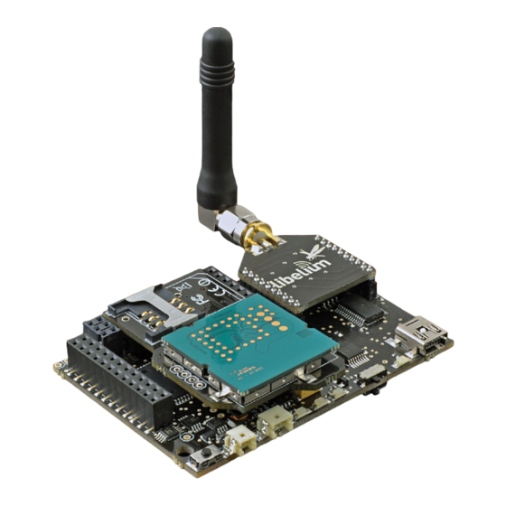
Page 91: Gsm/Gprs
GSM/GPRS 15. GSM/GPRS Waspmote can integrate a GSM (Global System for Mobile communications) / GPRS (General Packet Radio Service) module to enable communication using the mobile telephone network. • Model: SIM900 (SIMCom) Quadband: 850MHz/900MHz/1800MHz/1900MHz • TX Power: 2W(Class 4) 850MHz/900MHz, 1W(Class 1) 1800MHz/1900MHz •... - Page 92 GSM/GPRS This model uses the UART_1 at a baudarte of 57600bps speed to communicate with the microcontroller. Figure: GSM/GPRS module in Waspmote Related API libraries: WaspGPRS_Pro.h, WaspGPRS_Pro.cpp , WaspGPRS_Pro_core.h and WaspGPRS_Pro_core.cpp All information about their programming and operation can be found in the document: GSM/GPRS Programming Guide.
-
Page 93: Gprs+Gps
GPRS+GPS 16. GPRS+GPS Waspmote can integrate a GSM (Global System for Mobile communications) / GPRS (General Packet Radio Service) module to enable communication using the mobile telephone network. Also, this module integrates a GPS receiver. Model: SIM928 (SIMCom) GPRS features:... - Page 94 GPRS_SIM928A.makeLostCall(number, timeCall); This model uses the UART_1 at a baudarte of 57600bps speed to communicate with the microcontroller. Figure: GPRS+GPS module in Waspmote Related API libraries: WaspGPRS_SIM928A.h, WaspGPRS_SIM928A.cpp, WaspGPRS_Pro_core.h and WaspGPRS_Pro_core. All information about their programming and operation can be found in the document: GPRS+GPS Programming Guide.
-
Page 95: G + Gprs
3G + GPRS 17. 3G + GPRS Waspmote can integrate a UMTS (Universal Mobile Telecommunication System based in WCDMA technology) / GPRS (General Packet Radio Service) module to enable communication using the 3G/GPRS mobile telephone network. • Model: SIM5215 (SIMCom) •... - Page 96 _3G.makeLostCall(number, timeCall); This model uses the UART_1 at a baudrate of 115200 speed to communicate with the microcontroller. Figure: 3G/GPRS module in Waspmote Related API libraries: Wasp3G.h, Wasp3G.cpp All information about programming and operation can be found in the document: 3G + GPRS Networking Guide.
-
Page 97: Rfid/Nfc
Related API libraries: WaspRFID13.cpp , WaspRFID13.h All information on its programming can be found in the document: RFID/NFC 13.56MHz Networking Guide. All the documentation is located in the Development section in the Libelium website. Figure: RFID cards Figure: RFID keyrings Figure: RFID sticker -97- v6.3... - Page 98 RFID/NFC -98- v6.3...
-
Page 99: Industrial Protocols
1º- Connect any sensor to an existing industrial bus Waspmote can be configured to work as a node in the network, inserting sensor data into the industrial bus already present. Waspmote can obtain information from more than 70 sensors currently integrated in the platform by using specific sensor boards (e.g.: CO, CO... -
Page 100: Modbus Module
• Space(0): Negative voltages (B-A < -200 mV) Figure: RS-485 / Modbus module • Available Signals: Tx+/Rx+, Tx-/Rx-(Half Duplex)Tx+,Tx-,Rx+,Rx-(Full Duplex) • Available sockets in Waspmote: socket 0 (special SPI Waspmote required) Applications: • Industrial Equipment • Machine to Machine (M2M) communications •... -
Page 101: Serial / Modbus Module
Mark(1): -5...-15 • Space(0): +5...+15 Figure: RS-232 Serial / Modbus module • Signals: Full Duplex (Rx, TX) • Available sockets in Waspmote: sockets 0 and 1 Applications: • Dial up modems • GPS receivers (typically NMEA 0183 at 4,800 bit/s) •... -
Page 102: Can Bus Module
Speed: 125 to 1000 Kbps • Signaling: differential • Voltage Levels: 0-5V Figure: Can Bus module • Signals: Half Duplex • Available sockets in Waspmote: socket 0 (special SPI Waspmote required) Applications: • Automotive applications • Home automation • Industrial Networking •... -
Page 103: Modbus
Industrial Protocols 19.5. Modbus The Modbus is a software library that can be operated physically on the RS-485 and RS-232 modules. Thus, Modbus is a software layer which provides with interesting services. Technical details: • Protocol: Modbus • Data area: Up to 255 bytes per job •... - Page 104 Industrial Protocols Figure: RS-485 / Modbus module on Waspmote All information about their programming and operation can be found in the documents: RS-485 Communication Guide, RS- 232 Communication Guide, CAN Bus Communication Guide, Modbus Communication Guide. All the documentation is located in the Development section in the Libelium website.
-
Page 105: Expansion Radio Board
• CAN bus - Bluetooth • etc. Remark: GPRS Pro, GPRS+GPS and 3G/GPRS modules do not need the Expansion Board to be connected to Waspmote. They can be plugged directly in the socket1. Applications: • Multifrequency Sensor Networks (2.4GHz - 868/900MHz) •... -
Page 106: Over The Air Programming (Ota)
802.15.4 and ZigBee. Besides, Libelium provides an OTA method based on FTP transmissions to be used with GPRS, GPRS+GPS, 3G and WiFi modules. Note that the concept of OTA may have some other names such as: •... -
Page 107: Concepts
Storage System: Once we have sent the program to Waspmote it will store it in the internal memory, a 2GB SD card. If we have into account that the maximum size for a program is 128KB, this means we can store thousands different firmware versions inside each node. -
Page 108: Ota With 3G/Gprs/Wifi Modules Via Ftp
This is the recommended way when deploying a real scenario. 21.3.2. OTA with 3G/GPRS/WiFi modules via FTP The reprogramming process in this type of OTA is initiated by Waspmote and it is supported by an FTP server. Steps: •... -
Page 109: Ota With 802.15.4/Zigbee Modules
Over the Air Programming (OTA) 21.4. OTA with 802.15.4/ZigBee modules 21.4.1. OTA Step by Step Locate the node or nodes to upgrade • Using the ‘scan_nodes’ function we can search for a specific node or send a global query looking for any node which is ready to be reprogrammed with the OTA process. - Page 110 Over the Air Programming (OTA) Send the new program • We can use the ‘send’ command with the unicast, multicast or broadcast option depending on how many nodes we want to reprogram at the same time. Figure: Sending new program via OTA Each node which receives the program sends a message to the gateway to inform of the success of the process.
- Page 111 Over the Air Programming (OTA) Reboot and start with the new program • In order to make the nodes start executing the new program, the gateway needs to send the ‘start_new_program’ command. Figure: OTA Gateway commands some Waspmotes to start a new program Each node which receives this packet will copy the program from the SD to the Flash memory and will start running the new binary.
-
Page 112: Ota Shell
21.5.1. Procedure The Waspmote reprogramming is done using an FTP server and an FTP client which is Waspmote itself. The FTP server can be configured by Meshlium. Otherwise, the user will have to setup an FTP server. Figure: OTA via FTP protocol -112- v6.3... -
Page 113: Setting The Ftp Server Configuration
Figure: OTA steps via FTP protocol 21.5.2. Setting the FTP server configuration The FTP server that Waspmote connects to needs a specific configuration so as to OTA work properly. There are two ways to set up the FTP server: •... -
Page 114: Encryption Libraries
Encryption Libraries 22. Encryption Libraries The Encryption Libraries are designed to add to the Waspmote sensor platform the capabilities necessary to protect the information gathered by the sensors. To do so two cryptography layers are defined: • Link Layer: In the first one all the nodes of the network share a common preshared key which is used to encrypt the in- formation using AES 128. - Page 115 Encryption Libraries Figure: Waspmote frame on OSI stack for communication Figure: Waspmote frame structure for communication Note: For more information read the “Encryption Programming Guide” in the Waspmote Development section -115- v6.3...
-
Page 116: Sd Memory Card
Figure: Micro-SD card Waspmote uses the FAT16 file system and can support cards up to 2GB. The information that Waspmote stores in files on the SD can be accessed from different operating systems such as Linux, Windows or Mac-OS. There are many SD card models; any of them has defective blocks, which are ignored when using the Waspmote’s SD library. - Page 117 Note: Make sure Waspmote is switched off before inserting or removing the SD card. Otherwise, the SD card could be damaged. Note: Waspmote must not be switched off or reseted while there are ongoing read or write operations in the SD card. Otherwise, the SD card could be damaged and data could be lost.
-
Page 118: Energy Consumption
24. Energy Consumption 24.1. Consumption tables Waspmote 15mA Sleep 55μA Deep Sleep 55μA Hibernate 0,06μA XBee SLEEP SENDING RECEIVING (Waspmote switches) XBee 802.15.4 PRO 56,68mA 0,12mA 0μA 187,58mA 57,08mA XBee ZigBee PRO 45,56mA 0,71mA 0μA 105mA 50,46mA XBee 868 60,82mA 0μA... - Page 119 Energy Consumption GPRS+GPS Connecting ~100mA Calling ~100mA Receiving Calls ~100mA Transmitting GPRS ~100mA SLEEP ~0μA GPS acquisition mode 72mA GPS tracking mode 67mA 3G/GPRS Connecting ~100mA Transmitting/Receiving GPRS ~100mA (1.2A – 2A during transmission slot every 4.7ms ) Transmitting/Receiving 3G ~300mA - 500mA SLEEP ~0μA...
-
Page 120: Power Supplies
25. Power supplies 25.1. Battery The battery included with Waspmote is a Lithium-ion battery (Li-Ion) with 3.7V nominal voltage. With regard to battery capacity, there are several possibilities: 6600mAh Li-Ion rechargeable, and 13000mAh, 26000mAh and 52000mAh non - rechargeable. Waspmote has a control and safety circuit which makes sure the battery charge current is always adequate. - Page 121 Power supplies Battery discharging and charging curves The following two images show battery discharging and charging curves. Battery discharging Figure: Typical discharging curve for battery Battery charging using USB Figure: Typical charging curve for battery -121- v6.3...
- Page 122 - Charging Charging by USB (with Waspmote operating) Warning: Batteries with voltage over 3.7V could irreparably damage Waspmote. Incorrect battery connection could irreparably damage Waspmote. DO NOT TRY TO RECHARGE THE NON-RECHARGEABLE BATTERY. IT MAY EXPLODE AND CAUSE INJURIES AND DESTROY THE EQUIPMENT.
-
Page 123: Solar Panel
Power supplies 25.2. Solar Panel The solar panel must be connected using the cable supplied. Both the mini USB connector and the solar panel connector allow only one connection position which must be respected without being forced into the incorrect position. In this way connection polarity is respected. Solar panels up to 12V are allowed. - Page 124 Power supplies The models supplied by Libelium are shown below: Rigid Solar Panel • 7V - 500mA Dimensions: 234 x 160 x 17 mm Figure: Rigid Solar Panel • Flexible Solar Panel 7.2V - 100mA Dimensions: 284 x 97 x 2 mm...
-
Page 125: Usb
Power supplies 25.3. USB Figure: Mini USB connector Waspmote’s USB power sources are: USB to PC connection USB to 220V connection USB to Vehicle connector connection The charging voltage through the USB has to be 5V. The maximum charging current through the USB is 100mA. - Page 126 Power supplies The models supplied by Libelium are shown below: Figure: 220V AC – USB adapter Figure: 12V DC – USB car lighter adapter -126- v6.3...
-
Page 127: Working Environment
We advise to read this guide carefully. If it is the first time you plug a Waspmote on your PC and you are unable to see the proper USB port, maybe you should install the latest FTDI drivers: http://www.ftdichip.com/Drivers/D2XX.htm... -
Page 128: Compilation
In the next chapter is shown how to compile and upload a first program in Waspmote. 26.2. Compilation To use the Waspmote IDE compiler we must run the executable script called ‘Waspmote’ , which is in the folder where the compiler has been installed. - Page 129 Waspmote and how to show information on the screen. The next step is to configure the folder where the created programs are going to be saved. In the Waspmote IDE this folder is called ‘sketchbook’...
-
Page 130: Api
The basis for correct API operation is defined in these files. 1. WaspClasses.h: all the types to be run on the Waspmote API are defined. If any new type wants to be added, it will be necessary to include it in this file for correct compilation. -
Page 131: Libraries Folder
The functions that are common to GPRS Pro and GPRS+GPS modules are defined, such as send AT commands, HTTP request, FTP transfers that GPRS modules on Waspmote have. Besides, there are constants used in the libraries related to the GPRS Pro and GPRS+GPS modules. - Page 132 WaspOPC_N2: WaspOPC_N2.h, WaspOPC_N2.cpp SensorPrototyping_v20: WaspSensorPrototyping_v20.h, WaspSensorPrototyping_v20.cpp SensorRadiation: WaspSensorRadiation.h, WaspSensorRadiation.cpp The functions needed to manage the different sensor boards available on Waspmote. XBee Libraries The functions needed to set up, control and use a 802.15.4/ZigBee network. XBee802: WaspXBee802.h, WaspXBee802.cpp: the specific functions of the XBee 802.15.4 and the shared general library functions are inherited.
- Page 133 Working environment Sigfox Files: WaspSigfox.h, WaspSigfox.cpp The functions needed to manage the Sigfox module. Frame Files: WaspFrame.h, WaspFrame.cpp The functions needed to create new data frames by adding different sensor values. StackEEPROM Files:WaspStackEEPROM.h, WaspStackEEPROM .cpp The functions needed to use the EEPROM available memory like an stack. Bluetooth Pro Files: WaspBT_Pro.h, WaspBT_Pro.cpp The functions needed to manage the Bluetooth module for scanning devices.
-
Page 134: Updating The Libraries
Working environment 26.4. Updating the libraries To update the libraries, some files in the folder where the Waspmote IDE compiler was installed must be modified. The libraries are compatible with the different environments explained previously: Linux, Windows and Mac-OS. New versions of the libraries can be downloaded from the page: http://www.libelium.com/development/waspmote/sdk_and_applications... -
Page 135: Interacting With Waspmote
27.1.1. Waspmote Gateway This device allows to collect data which flows through the sensor network into a PC or device with a standard USB port. Waspmote Gateway will act as a ”data bridge or access point” between the sensor network and the receiving equipment. This receiving equipment will be responsible for storing and using the data received depending on the specific needs of the application. -
Page 136: Linux Receiver
The speed that must be selected is 115200 which is the standard speed set up for Waspmote. The USB where Waspmote has been connected must be added the first time this application is run, adding USB0, USB1, etc (up to the USB number of each computer) according to where Waspmote has been connected. For this, the ‘Device’ window must be modified so that if Waspmote is connected to USB0, this window contains ‘/dev/ttyUSB0’... - Page 137 Interacting with Waspmote Figure: Cutecom application capturing Waspmote’s output Linux Sniffer As well as using the terminal to see the sensor information, an application which allows this captured data to be dumped to a file or passed to another program to be used or checked has been developed.
- Page 138 Interacting with Waspmote #include <termios.h> /* Terminal control library (POSIX) */ #define MAX 100 main(int argc, char *argv[]) int sd=3; char *serialPort=””; char *serialPort0 = ”/dev/ttyS0”; char *serialPort1 = ”/dev/ttyS1”; char *USBserialPort0 = ”/dev/ttyUSB0”; char *USBserialPort1 = ”/dev/ttyUSBS1”; char valor[MAX] = ””;...
- Page 139 Interacting with Waspmote else if (!sd) sd = open(serialPort, O_RDWR | O_NOCTTY | O_NDELAY); //fprintf(stderr,”Serial Port open at: %i\n”, sd); fcntl(sd, F_SETFL, 0); tcgetattr(sd, &opciones); cfsetispeed(&opciones, B19200); cfsetospeed(&opciones, B19200); opciones.c_cflag |= (CLOCAL | CREAD); /*No parity*/ opciones.c_cflag &= ~PARENB; opciones.c_cflag &= ~CSTOPB;...
-
Page 140: Windows Receiver
Once this application is launched the connection must be configured. The first step is to give it a name: Figure: Step 1 of establishing connection The next step is to specify the port on which Waspmote has been connected, in this case the system recognizes it as ‘COM9’ , (this will vary on each computer):... - Page 141 The next step is to specify the speed and configuration parameters: Figure: Step 3 of establishing connection Once these steps have been performed connection with Waspmote has been established, and listening to the serial port begins. Figure: HyperTerminal application capturing Waspmote’s output.
-
Page 142: Mac-Os Receiver
If MAC OS X is used (version later than 10.3.9) the application ‘ZTERM’ can be used to capture the serial port output. This application can be downloaded from: http://homepage.mac.com/dalverson/zterm/ This application is configured automatically, establishing the USB on which Waspmote has been connected and the speed. The following image shows this application capturing Waspmote’s output, while the example code ‘Waspmote Accelerator Basic Example’... -
Page 143: Meshlium
Figure: Meshlium router Meshlium is a Linux router which works as the Gateway of the Waspmote Sensor Networks. It can contain 5 different radio interfaces: WiFi 2.4GHz, WiFi 5GHz, 3G/GPRS, Bluetooth and XBee/LoRa. As well as this, Meshlium can be solar and battery powered. -
Page 144: How Do They Work Together
Interacting with Waspmote 27.2.2. How do they work together? Meshlium receives the sensor data sent by Waspmote using its wireless radios. Then 4 possible actions can be performed: Store the sensor data in the Meshlium Local Data Base (MySQL) Store the sensor data in an External Data Base (MySQL) -
Page 145: Capturing And Storing Sensor Data In Meshlium From A Waspmote Sensor Network
Gateway. Later, once the user has developed the code for transmitting to Gateway, he can switch to Meshlium. Meshlium will receive the sensor data sent by Waspmote using the wireless radio and it will store the frames in the Local Data Base. - Page 146 Interacting with Waspmote Now you can open your browser and access to the Meshlium Manager System: • URL: http://10.10.10.1/ManagerSystem • user: root • password: libelium Figure: Meshlium Manager System Login screen Now we go to the “Sensor Networks” tab. Figure: Sensor Networks tab -146- v6.3...
- Page 147 Interacting with Waspmote There are 6 different RF models can be configured: Figure: XBee and LoRa radio models Depending the kind of XBee model the parameters to be configured may vary. Complete list: • Network ID: Also known as PAN ID (Personal Arena Network ID) •...
- Page 148 Interacting with Waspmote These parameters must be also configured in the Waspmote sensor nodes. Access to all the information related to Waspmote at: http://www.libelium.com/waspmote Figure: XBee parameters configuration To discover the MAC address of the XBee module just press the “Load MAC” button.
- Page 149 In order to work with new sensor information added to the frames go to the “Capturing and Storing new sensor data frames” chapter. If you change any of the parameters in Waspmote or Meshlium you will have to do it in both platforms so that they still can communicate.
- Page 150 Interacting with Waspmote We can perform two different storage options with the frames captured: Figure: Meshlium Storage options • Local Data Base • External Data Base You can also send the information received to the Internet using the Ethernet, WiFi and 3G/GPRS interfaces.
- Page 151 Interacting with Waspmote Local Data Base Meshlium has a MySQL data base up and running which is used to store locally the information captured. In the “Local Data Base” tab you can see the connection parameters. Database: • MeshliumDB Table: •...
- Page 152 Interacting with Waspmote External Data Base Meshlium can also store the information captured in an External Data Base. Steps: 1. Pressing the “Show sql script” you will get the code needed to create the data base along with the table and the right privile- ges.
- Page 153 Interacting with Waspmote 4. Now press the “Check Connection” button to see if the configuration is correct. Figure: External Database tab - checking connection -153- v6.3...
- Page 154 Interacting with Waspmote 5. Set the check box “Store frames in external database”, you can defined the interval how often to synchronize the local database with external database and press the “Save” button. From this time Meshlium will automatically perform Scans and will store the results in the External Data Base each . This process will also continue after restarting Meshlium.
- Page 155 Interacting with Waspmote At any time you can see the last “x” records stored. Just set how many insertions you want to see and press the “Show data” button. Figure: External Database tab - last “x” records stored -155- v6.3...
- Page 156 Interacting with Waspmote Show me now! In the “Show me now!” tab you can see in real time the Scans captured. You can specify if you want the information to be updated periodically with the defined interval just checking the “Use the Defined Interval”...
- Page 157 Interacting with Waspmote Advanced Database In the “Advanced” tab you can see information about the state in which they are databases. It displays information about the Loca and Externall database, showing the following information: • Local and External Database names •...
- Page 158 Interacting with Waspmote Figure: Advanved Tab – Remove data In addition can display a log of the date of the last synchronization between the local database and external database was successful. Figure: Advanved Tab – Synchronization log -158- v6.3...
-
Page 159: Capturer Logs
Interacting with Waspmote 27.2.4. Capturer logs Inside “Sensor Networks” exists the section Logs, in this section you can see the last frames received on Meshlium. Figure: Sensor log First show the “sensor log”, in this logs shows the frames are stored after being processed. -
Page 160: Sensors
27.2.5. Sensors In section “Sensor List”, the user can add new sensors or delete sensors. By default Meshlium recognize all Libelium official sensors frames. All sensors frames that Meshlium can capture and store must be specified in an XML file. -
Page 161: Sending Xbee Frames From Meshlium To Waspmote
Figure: Sensor List – Remove 27.2.6. Sending XBee frames from Meshlium to Waspmote Meshlium can also send XBee frames to the Waspmote nodes. In order to use this feature you have to stop the “capturing and storing” daemon which is running in the system. -
Page 162: Interacting With 3Rd Party Cloud Platforms
27.2.7. Interacting with 3rd party Cloud platforms Libelium has partnered with the best Cloud software solution providers to offer you all the necessary components to deploy Internet of Things (IoT), machine-to-machine (M2M) or Smart Cities projects with minimum time-to-market. Meshlium is ready to send sensor data to many Cloud software platforms. -
Page 163: Documentation Changelog
Added references to the new Industrial Protocols line • Added references to the new Turbidity sensor for Smart Water • Deleted chapter “Waspmote v11 VS Waspmote v12” (transition cycle completed) From 5.3 to 5.4 • Added references to the new Industrial Protocols line •... - Page 164 Added references to OTA with 3G/GPRS/WiFi via FTP • Magnet reset reference in Plug & Sense! • Note about consumption in sleep modes (XBee + Waspmote + SD card) • Reference to next line of calibrated Gas Board • Some changes in Recommendations of Use •...
- Page 165 Documentation Changelog From v4.1 to v4.2 • Added references to 3G module • Better IDE explanation on Linux • Some errata and better explanations -165- v6.3...
-
Page 166: Certifications
If desired, the Declaration of Conformity document can be requested using the Contact section at: http://www.libelium.com/contact Waspmote is a piece of equipment defined as a wireless sensor capture, geolocalization and communication device which allows: • short and long distance data, voice and image communication •... -
Page 167: Fcc
FCC ID: XKM-WASP03 comprising - FCC ID: MCQ-XBEE09P - FCC ID: UDV-0912142009007 Installation and operation of any Waspmote model must assure a separation distance of 20 cm from all persons, to comply with RF exposure restrictions. Module Grant Restrictions FCC ID OUR-XBEEPRO The antenna(s) used for this transmitter must be installed to provide the separation distances, as described in this filing, and must not be co-located or operating in conjunction with any other antenna or transmitter. -
Page 168: Use Of Equipment Characteristics
The term “IC:” before the equipment certification number only signifies that the Industry Canada technical specifications were met. Installation and operation of any Waspmote model must assure a separation distance of 20 cm from all persons, to comply with RF exposure restrictions. - Page 169 It is the responsibility of the installer to find out about restrictions of use for frequency bands in each country and act in accordance with the given regulations. Libelium Comunicaciones Distribuidas S.L does not list the entire set of standards that must be met for each country.
-
Page 170: Maintenance
Maintenance 30. Maintenance • In this section, the term “Waspmote” encompasses both the Waspmote device itself as well as its modules and sensor boards. • Take care when handling Waspmote, do not let it fall, knock it or move it suddenly. -
Page 171: Disposal And Recycling
Disposal and recycling 31. Disposal and recycling • In this section, the term “Waspmote” encompasses both the Waspmote device itself as well as its modules and sensor boards. • When Waspmote reaches the end of its useful life, it must be taken to an electronic equipment recycling point.
Need help?
Do you have a question about the Waspmote and is the answer not in the manual?
Questions and answers