
Subscribe to Our Youtube Channel
Related Manuals for Beckhoff EtherCAT EL600x Series


Summary of Contents for Beckhoff EtherCAT EL600x Series
- Page 1 Documentation EL600x, EL602x Serial Interface Terminals Version: Date: 2018-09-24...
-
Page 3: Table Of Contents
Table of contents Table of contents 1 Foreword .............................. 5 Overview Serial Interface Terminals.................... 5 Notes on the documentation...................... 5 Safety instructions .......................... 7 Documentation Issue Status...................... 8 Version identification of EtherCAT devices .................. 9 2 Product overview............................. 14 EL6001, EL6021 .......................... 18 2.1.1 Introduction ........................ 18 2.1.2 Technical data ......................... - Page 4 Table of contents 5.2.1 Installation of the TwinCAT real-time driver.............. 80 5.2.2 Notes regarding ESI device description................ 86 5.2.3 TwinCAT ESI Updater ..................... 90 5.2.4 Distinction between Online and Offline................ 90 5.2.5 OFFLINE configuration creation .................. 91 5.2.6 ONLINE configuration creation .................. 96 5.2.7 EtherCAT subscriber configuration................
-
Page 5: Foreword
The TwinCAT Technology is covered, including but not limited to the following patent applications and patents: EP0851348, US6167425 with corresponding applications or registrations in various other countries. ® EtherCAT is registered trademark and patented technology, licensed by Beckhoff Automation GmbH, Germany EL600x, EL602x Version: 4.6... - Page 6 Foreword Copyright © Beckhoff Automation GmbH & Co. KG, Germany. The reproduction, distribution and utilization of this document as well as the communication of its contents to others without express authorization are prohibited. Offenders will be held liable for the payment of damages. All rights reserved in the event of the grant of a patent, utility model or design.
-
Page 7: Safety Instructions
All the components are supplied in particular hardware and software configurations appropriate for the application. Modifications to hardware or software configurations other than those described in the documentation are not permitted, and nullify the liability of Beckhoff Automation GmbH & Co. KG. Personnel qualification This description is only intended for trained specialists in control, automation and drive engineering who are familiar with the applicable national standards. -
Page 8: Documentation Issue Status
Foreword Documentation Issue Status Version Comment • Correction RS232 level • Update chapter "Technical data" • Update structure • Update revision status • Update chapter "Commissioning" • Update revision status • Update chapter "Technical data" • Update chapter "Operating modes and process data" •... -
Page 9: Version Identification Of Ethercat Devices
• First public issue • Addenda • Corrections and addenda • Preliminary documentation for EL60xx Version identification of EtherCAT devices Designation A Beckhoff EtherCAT device has a 14-digit designation, made up of • family key • type • version • revision Example... - Page 10 Production lot/batch number/serial number/date code/D number The serial number for Beckhoff IO devices is usually the 8-digit number printed on the device or on a sticker. The serial number indicates the configuration in delivery state and therefore refers to a whole production batch, without distinguishing the individual modules of a batch.
-
Page 11: Fig. 1 El5021 El Terminal, Standard Ip20 Io Device With Serial/ Batch Number And Revision Id (Since 2014/01)
Foreword Examples of markings Fig. 1: EL5021 EL terminal, standard IP20 IO device with serial/ batch number and revision ID (since 2014/01) Fig. 2: EK1100 EtherCAT coupler, standard IP20 IO device with serial/ batch number Fig. 3: CU2016 switch with serial/ batch number EL600x, EL602x Version: 4.6... -
Page 12: Fig. 4 El3202-0020 With Serial/ Batch Number 26131006 And Unique Id-Number 204418
Foreword Fig. 4: EL3202-0020 with serial/ batch number 26131006 and unique ID-number 204418 Fig. 5: EP1258-00001 IP67 EtherCAT Box with batch number/ date code 22090101 and unique serial number 158102 Fig. 6: EP1908-0002 IP67 EtherCAT Safety Box with batch number/ date code 071201FF and unique serial number 00346070 Fig. 7: EL2904 IP20 safety terminal with batch number/ date code 50110302 and unique serial number 00331701... -
Page 13: Fig. 8 Elm3604-0002 Terminal With Unique Id Number (Qr Code) 100001051 And Serial/ Batch Num- Ber 44160201
Foreword Fig. 8: ELM3604-0002 terminal with unique ID number (QR code) 100001051 and serial/ batch number 44160201 EL600x, EL602x Version: 4.6... -
Page 14: Product Overview
Product overview Product overview Technology The EL600x and EL602x serial interface terminals enable the connection of devices with an RS232 (or RS485 / RS422) interface. In the case of the EL600x, the data is exchanged with the controller in full duplex mode;... -
Page 15: Fig. 9 Level Interfaces Rs232, Rs485/422
Product overview Level interfaces The EL6001/6002 devices operate at an RS232 level with reference to GND, the EL6021/6022 devices with a differential RS485/422 level. Fig. 9: Level interfaces RS232, RS485/422 Termination and topology The serial RS422 and RS485 communication technologies operate with voltage levels on a 2-wire line. Reflections at high-resistance line ends can lead to signal distortion. -
Page 16: Fig. 11 Rs485 Termination
Product overview Fig. 11: RS485 termination The background is the different design of RS422/EIA-422 and RS485/EIA-485: • RS422: 1 Rx → Tx n (maximum 10 receivers) • RS485: n Rx → Tx m (maximum 32/128 devices, depending on the resulting bus loading) Components for RS485 usually have a higher input impedance, resulting in lower bus load. -
Page 17: Fig. 12 El60Xx Shield Connection
Product overview Fig. 12: EL60xx shield connection In the 2-channel versions the D-Sub 9 shield is connected with the mounting rail via a high-resistance RC combination. EL600x, EL602x Version: 4.6... -
Page 18: El6001, El6021
Product overview EL6001, EL6021 2.1.1 Introduction Serial Interface Terminal (RS232C/RS422/RS485), 1 channel The EL6001 and EL6021 serial interfaces enable the connection of devices with RS-232 or RS422/RS485 interface. The EL6001 operates in conformity with the CCITT V.28/DIN 66 259-1 standards. The device connected to the EL6001 EtherCAT Terminal communicates with the automation device via the coupler. -
Page 19: Technical Data
Product overview 2.1.2 Technical data Technical data EL6001 EL6021 Data transfer channels TxD and RxD, full duplex TxD and RxD, full/half duplex Data transfer rate 2400...115200 baud, 2400...115200 baud, default: 9600 baud, 8 data bits, default: 9600 baud, 8 data bits, no parity, 1 stop bit no parity, 1 stop bit from firmware 07 [} 186]: also 12000 baud and... -
Page 20: El6002, El6022
Product overview EL6002, EL6022 2.2.1 Introduction Serial Interface Terminal (RS232C/RS422/RS485), 2 channel The EL6002 and EL6022 serial interfaces enable the connection of devices with two RS232 or two RS422/ RS485 interfaces each with one D-Sub connector (9 pin). The interfaces are electrically isolated from each other and from the EtherCAT. -
Page 21: Technical Data
Product overview 2.2.2 Technical data Technical data EL6002 EL6022 Data transfer channels 2, TxD and RxD, full duplex 2, TXD and RXD, full/half duplex Connection 2 x D-sub connector (DE9), 9-pin 2 x D-sub connector (DE9), 9-pin Data transfer rate 300...115200 baud default: 9600 baud, 8 data bits, no parity, 1 stop bit Data buffer... -
Page 22: Basics Communication
EtherCAT devices from Beckhoff. Recommended cables Suitable cables for the connection of EtherCAT devices can be found on the Beckhoff website! E-Bus supply A bus coupler can supply the EL terminals added to it with the E-bus system voltage of 5 V; a coupler is thereby loadable up to 2 A as a rule (see details in respective device documentation). -
Page 23: General Notes For Setting The Watchdog
Basics communication Fig. 13: System manager current calculation NOTE Malfunction possible! The same ground potential must be used for the E-Bus supply of all EtherCAT terminals in a terminal block! General notes for setting the watchdog ELxxxx terminals are equipped with a safety feature (watchdog) that switches off the outputs after a specifiable time e.g. -
Page 24: Fig. 14 Ethercat Tab -> Advanced Settings -> Behavior -> Watchdog
Basics communication Fig. 14: EtherCAT tab -> Advanced Settings -> Behavior -> Watchdog Notes: • the multiplier is valid for both watchdogs. • each watchdog has its own timer setting, the outcome of this in summary with the multiplier is a resulting time. -
Page 25: Ethercat State Machine
Basics communication Example "Set SM watchdog" This checkbox enables manual setting of the watchdog times. If the outputs are set and the EtherCAT communication is interrupted, the SM watchdog is triggered after the set time and the outputs are erased. This setting can be used for adapting a terminal to a slower EtherCAT master or long cycle times. -
Page 26: Fig. 15 States Of The Ethercat State Machine
Basics communication Fig. 15: States of the EtherCAT State Machine Init After switch-on the EtherCAT slave in the Init state. No mailbox or process data communication is possible. The EtherCAT master initializes sync manager channels 0 and 1 for mailbox communication. Pre-Operational (Pre-Op) During the transition between Init and Pre-Op the EtherCAT slave checks whether the mailbox was initialized correctly. -
Page 27: Coe Interface
Basics communication Boot In the Boot state the slave firmware can be updated. The Boot state can only be reached via the Init state. In the Boot state mailbox communication via the file access over EtherCAT (FoE) protocol is possible, but no other mailbox communication and no process data communication. -
Page 28: Fig. 16 "Coe Online " Tab
Data management If slave CoE parameters are modified online, Beckhoff devices store any changes in a fail-safe manner in the EEPROM, i.e. the modified CoE parameters are still available after a restart. The situation may be different with other manufacturers. -
Page 29: Fig. 17 Startup List In The Twincat System Manager
Changes in the local CoE list of the terminal are lost if the terminal is replaced. If a terminal is re- placed with a new Beckhoff terminal, it will have the default settings. It is therefore advisable to link all changes in the CoE list of an EtherCAT slave with the Startup list of the slave, which is pro- cessed whenever the EtherCAT fieldbus is started. -
Page 30: Fig. 18 Offline List
Basics communication Fig. 18: Offline list • If the slave is online ◦ The actual current slave list is read. This may take several seconds, depending on the size and cycle time. ◦ The actual identity is displayed ◦ The firmware and hardware version of the equipment according to the electronic information is displayed ◦... - Page 31 • Channel 1: parameter range 0x8010:00 ... 0x801F:255 • Channel 2: parameter range 0x8020:00 ... 0x802F:255 • ... This is generally written as 0x80n0. Detailed information on the CoE interface can be found in the EtherCAT system documentation on the Beckhoff website. EL600x, EL602x Version: 4.6...
-
Page 32: Distributed Clock
Basics communication Distributed Clock The distributed clock represents a local clock in the EtherCAT slave controller (ESC) with the following characteristics: • Unit 1 ns • Zero point 1.1.2000 00:00 • Size 64 bit (sufficient for the next 584 years; however, some EtherCAT slaves only offer 32-bit support, i.e. -
Page 33: Mounting And Wiring
Each assembly must be terminated at the right hand end with an EL9011 or EL9012 bus end cap, to en- sure the protection class and ESD protection. Fig. 20: Spring contacts of the Beckhoff I/O components EL6001, EL6021 4.2.1... -
Page 34: Fig. 21 Attaching On Mounting Rail
Mounting and Wiring Assembly Fig. 21: Attaching on mounting rail The bus coupler and bus terminals are attached to commercially available 35 mm mounting rails (DIN rails according to EN 60715) by applying slight pressure: 1. First attach the fieldbus coupler to the mounting rail. 2. -
Page 35: Fig. 22 Disassembling Of Terminal
Mounting and Wiring Disassembly Fig. 22: Disassembling of terminal Each terminal is secured by a lock on the mounting rail, which must be released for disassembly: 1. Pull the terminal by its orange-colored lugs approximately 1 cm away from the mounting rail. In doing so for this terminal the mounting rail lock is released automatically and you can pull the terminal out of the bus terminal block easily without excessive force. -
Page 36: Connection
Mounting and Wiring Fig. 23: Power contact on left side NOTE Possible damage of the device Note that, for reasons of electromagnetic compatibility, the PE contacts are capacitatively coupled to the mounting rail. This may lead to incorrect results during insulation testing or to damage on the terminal (e.g. disruptive discharge to the PE line during insulation testing of a consumer with a nominal voltage of 230 V). -
Page 37: Fig. 24 Standard Wiring
Mounting and Wiring Standard wiring (ELxxxx / KLxxxx) Fig. 24: Standard wiring The terminals of ELxxxx and KLxxxx series have been tried and tested for years. They feature integrated screwless spring force technology for fast and simple assembly. Pluggable wiring (ESxxxx / KSxxxx) Fig. 25: Pluggable wiring The terminals of ESxxxx and KSxxxx series feature a pluggable connection level. -
Page 38: Fig. 27 Connecting A Cable On A Terminal Point
Mounting and Wiring Wiring HD Terminals The High Density (HD) Terminals of the ELx8xx and KLx8xx series doesn't support pluggable wiring. Ultrasonically "bonded" (ultrasonically welded) conductors Ultrasonically “bonded" conductors It is also possible to connect the Standard and High Density Terminals with ultrasonically "bonded"... -
Page 39: Fig. 26 High Density Terminals
Mounting and Wiring Terminal housing ELxxxx, KLxxxx ESxxxx, KSxxxx Wire size width (single core wires) 0.08 ... 2.5 mm 0.08 ... 2.5 mm Wire size width (fine-wire conductors) 0.08 ... 2.5 mm 0,08 ... 2.5 mm Wire size width (conductors with a wire end sleeve) 0.14 ... -
Page 40: Positioning Of Passive Terminals
Mounting and Wiring 4.2.3 Positioning of passive Terminals Hint for positioning of passive terminals in the bus terminal block EtherCAT Terminals (ELxxxx / ESxxxx), which do not take an active part in data transfer within the bus terminal block are so called passive terminals. The passive terminals have no current consump- tion out of the E-Bus. -
Page 41: Leds And Terminal Connector Assignments
Mounting and Wiring 4.2.4 LEDs and terminal connector assignments LEDs Fig. 30: EL6001, EL6021 - LEDs and Connection Color Meaning Green This LED indicates the terminal's operating state: State of the EtherCAT State Machine [} 25]: INIT = initialization of the terminal or BOOTSTRAP = function for firmware updates [} 187] of the terminal flashing State of the EtherCAT state machine: PREOP = function for mailbox... -
Page 42: Fig. 31 El6001, El6021 - Leds And Connection
Mounting and Wiring Connection Fig. 31: EL6001, EL6021 - LEDs and Connection EL6001 terminal connector assignments Terminal point Name Signal Signal line (Transmit Data) Signal line (Receive Data) Control line (Request To Send) Control line (Clear To Send) Ground (internally bridged with terminal 7) Ground (internally bridged with terminal 3) Shield Shield (internally bridged with terminal 8) -
Page 43: El6002, El6022
Mounting and Wiring Connection for RS422 transfer In RS422 mode, data can be transferred in full duplex mode. Only point to point connections can be established. Fig. 32: Connection for RS422 transfer Connection for RS485 transfer In RS485 mode, data are exchanged in half duplex mode. A bus structure can be created in this mode of operation. - Page 44 Mounting and Wiring Fixing of mounting rails The locking mechanism of the terminals and couplers extends to the profile of the mounting rail. At the installation, the locking mechanism of the components must not come into conflict with the fixing bolts of the mounting rail.
-
Page 45: Recommended Mounting Rails
Mounting and Wiring • Pull (4) the terminal module away from the mounting surface. Avoid canting of the module; you should stabilize the module with the other hand, if required. 4.3.2 Recommended mounting rails Terminal Modules und EtherCAT Modules of KMxxxx and EMxxxx series, same as the terminals of the EL66xx and EL67xx series can be snapped onto the following recommended mounting rails: DIN Rail TH 35-7.5 with 1 mm material thickness (according to EN 60715) DIN Rail TH 35-15 with 1,5 mm material thickness... -
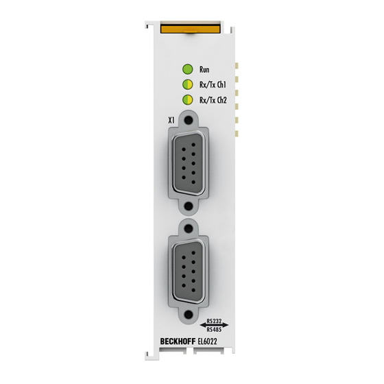
Page 46: Leds And Pin Assignment
Mounting and Wiring 4.3.3 LEDs and pin assignment Fig. 34: EL6002, EL6022 - LEDs LEDs Color Meaning Green This LED indicates the terminal's operating state: State of the EtherCAT State Machine [} 25]: INIT = initialization of the terminal or BOOTSTRAP = function for firmware updates [} 187] of the terminal flashing State of the EtherCAT State Machine: PREOP = function for mailbox... - Page 47 Mounting and Wiring EL6002 pin assignment 2 x D-Sub connector, male; 9-pin D-Sub connector, male Pin assignment channel 1 Pin assignment channel 2 (plan view) RS232 RS232 DCD (internally bridged with DCD (internally bridged with pins pins 4 and 6) 4 and 6) RxCH1 RxCH2...
-
Page 48: Fig. 35 Connection For Rs422 Transfer
Mounting and Wiring Connection for RS422 transfer In RS422 mode, data can be transferred in full duplex mode. Only point to point connections can be established. Fig. 35: Connection for RS422 transfer Connection for RS485 transfer In RS485 mode, data are exchanged in half duplex mode. A bus structure can be created in this mode of operation. -
Page 49: Positioning Of Passive Terminals
Mounting and Wiring Positioning of passive Terminals Hint for positioning of passive terminals in the bus terminal block EtherCAT Terminals (ELxxxx / ESxxxx), which do not take an active part in data transfer within the bus terminal block are so called passive terminals. The passive terminals have no current consump- tion out of the E-Bus. -
Page 50: Installation Instructions For Enhanced Mechanical Load Capacity
Mounting and Wiring Installation instructions for enhanced mechanical load capacity WARNING Risk of injury through electric shock and damage to the device! Bring the Bus Terminal system into a safe, de-energized state before starting mounting, disassembly or wiring of the Bus Terminals! Additional checks The terminals have undergone the following additional tests: Verification... -
Page 51: Installation Positions
Mounting and Wiring Installation positions NOTE Constraints regarding installation position and operating temperature range Please refer to the technical data for a terminal to ascertain whether any restrictions regarding the installa- tion position and/or the operating temperature range have been specified. When installing high power dissi- pation terminals ensure that an adequate spacing is maintained between other components above and be- low the terminal in order to guarantee adequate ventilation! Optimum installation position (standard) -
Page 52: Fig. 40 Other Installation Positions
Mounting and Wiring Fig. 40: Other installation positions Version: 4.6 EL600x, EL602x... -
Page 53: Ul Notice
Beckhoff EtherCAT modules are intended for use with Beckhoff’s UL Listed EtherCAT Sys- tem only. Examination For cULus examination, the Beckhoff I/O System has only been investigated for risk of fire and electrical shock (in accordance with UL508 and CSA C22.2 No. 142). For devices with Ethernet connectors Not for connection to telecommunication circuits. -
Page 54: Atex - Special Conditions (Extended Temperature Range)
80°C at the wire branching points, then cables must be selected whose tempera- ture data correspond to the actual measured temperature values! • Observe the permissible ambient temperature range of -25 to 60°C for the use of Beckhoff fieldbus com- ponents with extended temperature range (ET) in potentially explosive areas! •... -
Page 55: Atex Documentation
Notes about operation of the Beckhoff terminal systems in potentially explosive ar- eas (ATEX) Pay also attention to the continuative documentation Notes about operation of the Beckhoff terminal systems in potentially explosive areas (ATEX) that is available in the download area of the Beckhoff homepage http:\\www.beckhoff.com! EL600x, EL602x... -
Page 56: Commissioning
• "offline": The configuration can be customized by adding and positioning individual components. These can be selected from a directory and configured. ◦ The procedure for offline mode can be found under http://infosys.beckhoff.com: TwinCAT 2 → TwinCAT System Manager → IO - Configuration → Adding an I/O Device •... -
Page 57: Fig. 41 Relationship Between User Side (Commissioning) And Installation
Commissioning Fig. 41: Relationship between user side (commissioning) and installation The user inserting of certain components (I/O device, terminal, box...) is the same in TwinCAT 2 and TwinCAT 3. The descriptions below relate to the online procedure. Sample configuration (actual configuration) Based on the following sample configuration, the subsequent subsections describe the procedure for TwinCAT 2 and TwinCAT 3: •... - Page 58 Commissioning Fig. 42: Control configuration with Embedded PC, input (EL1004) and output (EL2008) Note that all combinations of a configuration are possible; for example, the EL1004 terminal could also be connected after the coupler, or the EL2008 terminal could additionally be connected to the CX2040 on the right, in which case the EK1100 coupler wouldn’t be necessary.
- Page 59 Commissioning Generally, TwinCAT can be used in local or remote mode. Once the TwinCAT system including the user interface (standard) is installed on the respective PLC, TwinCAT can be used in local mode and thereby the next step is "Insert Device [} 60]". If the intention is to address the TwinCAT runtime environment installed on a PLC as development environment remotely from another system, the target system must be made known first.
- Page 60 Commissioning After confirmation with "OK" the target system can be accessed via the System Manager. Adding devices In the configuration tree of the TwinCAT 2 System Manager user interface on the left, select "I/O Devices” and then right-click to open a context menu and select "Scan Devices…", or start the action in the menu bar .
- Page 61 Commissioning Fig. 48: Mapping of the configuration in the TwinCAT 2 System Manager The whole process consists of two stages, which may be performed separately (first determine the devices, then determine the connected elements such as boxes, terminals, etc.). A scan can also be initiated by selecting "Device ..."...
- Page 62 Commissioning • Graphical languages ◦ Function Block Diagram (FBD) ◦ Ladder Diagram (LD) ◦ The Continuous Function Chart Editor (CFC) ◦ Sequential Function Chart (SFC) The following section refers to Structured Text (ST). After starting TwinCAT PLC Control, the following user interface is shown for an initial project: Fig. 50: TwinCAT PLC Control after startup Sample variables and a sample program have been created and stored under the name "PLC_example.pro": Version: 4.6...
- Page 63 Commissioning Fig. 51: Sample program with variables after a compile process (without variable integration) Warning 1990 (missing "VAR_CONFIG") after a compile process indicates that the variables defined as external (with the ID "AT%I*" or "AT%Q*") have not been assigned. After successful compilation, TwinCAT PLC Control creates a "*.tpy"...
- Page 64 Commissioning Select the PLC configuration "PLC_example.tpy" in the browser window that opens. The project including the two variables identified with "AT" are then integrated in the configuration tree of the System Manager: Fig. 53: PLC project integrated in the PLC configuration of the System Manager The two variables "bEL1004_Ch4"...
- Page 65 Commissioning Fig. 55: Selecting PDO of type BOOL According to the default setting, certain PDO objects are now available for selection. In this sample the input of channel 4 of the EL1004 terminal is selected for linking. In contrast, the checkbox "All types" must be ticked for creating the link for the output variables, in order to allocate a set of eight separate output bits to a byte variable.
- Page 66 Commissioning Fig. 57: Application of a "Goto Link" variable, using "MAIN.bEL1004_Ch4" as a sample The process of assigning variables to the PDO is completed via the menu selection "Actions" → "Generate Mappings”, key Ctrl+M or by clicking on the symbol in the menu. This can be visualized in the configuration: The process of creating links can also take place in the opposite direction, i.e.
- Page 67 Commissioning Fig. 58: Choose target system (remote) In this sample "Runtime system 1 (port 801)" is selected and confirmed. Link the PLC with the real-time system via menu option "Online" → "Login", the F11 key or by clicking on the symbol . The control program can then be loaded for execution.
- Page 68 Commissioning Fig. 59: PLC Control logged in, ready for program startup The PLC can now be started via "Online" → "Run", F5 key or 5.1.2 TwinCAT 3 Startup TwinCAT makes the development environment areas available together with Microsoft Visual Studio: after startup, the project folder explorer appears on the left in the general window area (cf.
- Page 69 Commissioning Fig. 60: Initial TwinCAT 3 user interface First create a new project via (or under "File"→“New"→ "Project…"). In the following dialog make the corresponding entries as required (as shown in the diagram): Fig. 61: Create new TwinCAT project The new project is then available in the project folder explorer: EL600x, EL602x Version: 4.6...
- Page 70 Commissioning Fig. 62: New TwinCAT3 project in the project folder explorer Generally, TwinCAT can be used in local or remote mode. Once the TwinCAT system including the user interface (standard) is installed on the respective PLC, TwinCAT can be used in local mode and thereby the next step is "Insert Device [} 71]".
- Page 71 Commissioning Use "Search (Ethernet)..." to enter the target system. Thus a next dialog opens to either: • enter the known computer name after "Enter Host Name / IP:" (as shown in red) • perform a "Broadcast Search" (if the exact computer name is not known) •...
- Page 72 Commissioning Fig. 66: Automatic detection of I/O devices: selection the devices to be integrated Confirm the message "Find new boxes", in order to determine the terminals connected to the devices. "Free Run" enables manipulation of input and output values in "Config mode" and should also be acknowledged. Based on the sample configuration [} 57] described at the beginning of this section, the result is as follows: Fig. 67: Mapping of the configuration in VS shell of the TwinCAT3 environment The whole process consists of two stages, which may be performed separately (first determine the devices,...
- Page 73 Commissioning Fig. 68: Reading of individual terminals connected to a device This functionality is useful if the actual configuration is modified at short notice. Programming the PLC TwinCAT PLC Control is the development environment for the creation of the controller in different program environments: TwinCAT PLC Control supports all languages described in IEC 61131-3.
- Page 74 Commissioning Fig. 69: Adding the programming environment in "PLC" In the dialog that opens select "Standard PLC project" and enter "PLC_example" as project name, for example, and select a corresponding directory: Fig. 70: Specifying the name and directory for the PLC programming environment The "Main"...
- Page 75 Commissioning Fig. 71: Initial "Main" program of the standard PLC project To continue, sample variables and a sample program have now been created: EL600x, EL602x Version: 4.6...
- Page 76 Commissioning Fig. 72: Sample program with variables after a compile process (without variable integration) The control program is now created as a project folder, followed by the compile process: Fig. 73: Start program compilation The following variables, identified in the ST/ PLC program with "AT%", are then available in under "Assignments"...
- Page 77 Commissioning Fig. 74: Creating the links between PLC variables and process objects In the window that opens, the process object for the variable "bEL1004_Ch4" of type BOOL can be selected from the PLC configuration tree: Fig. 75: Selecting PDO of type BOOL According to the default setting, certain PDO objects are now available for selection.
- Page 78 Commissioning Fig. 76: Selecting several PDOs simultaneously: activate "Continuous" and "All types" Note that the "Continuous" checkbox was also activated. This is designed to allocate the bits contained in the byte of the variable "nEL2008_value" sequentially to all eight selected output bits of the EL2008 terminal. In this way it is possible to subsequently address all eight outputs of the terminal in the program with a byte corresponding to bit 0 for channel 1 to bit 7 for channel 8 of the PLC.
- Page 79 Commissioning Activation of the configuration The allocation of PDO to PLC variables has now established the connection from the controller to the inputs and outputs of the terminals. The configuration can now be activated with or via the menu under "TwinCAT"...
-
Page 80: Twincat 2
5.2.1 Installation of the TwinCAT real-time driver In order to assign real-time capability to a standard Ethernet port of an IPC controller, the Beckhoff real-time driver has to be installed on this port under Windows. This can be done in several ways. One option is described here. - Page 81 Commissioning Fig. 79: System Manager “Options” (TwinCAT 2) This have to be called up by the Menü “TwinCAT” within the TwinCAT 3 environment: Fig. 80: Call up under VS Shell (TwinCAT 3) The following dialog appears: Fig. 81: Overview of network interfaces Interfaces listed under “Compatible devices” can be assigned a driver via the “Install” button. A driver should only be installed on compatible devices.
- Page 82 Commissioning Fig. 82: EtherCAT device properties(TwinCAT 2): click on „Compatible Devices…“ of tab “Adapter” TwinCAT 3: the properties of the EtherCAT device can be opened by double click on “Device .. (EtherCAT)” within the Solution Explorer under “I/O”: After the installation the driver appears activated in the Windows overview for the network interface (Windows Start →...
- Page 83 Commissioning Fig. 84: Exemplary correct driver setting for the Ethernet port Other possible settings have to be avoided: EL600x, EL602x Version: 4.6...
- Page 84 Commissioning Fig. 85: Incorrect driver settings for the Ethernet port Version: 4.6 EL600x, EL602x...
- Page 85 Commissioning IP address of the port used IP address/DHCP In most cases an Ethernet port that is configured as an EtherCAT device will not transport general IP packets. For this reason and in cases where an EL6601 or similar devices are used it is useful to specify a fixed IP address for this port via the “Internet Protocol TCP/IP”...
-
Page 86: Notes Regarding Esi Device Description
The files are read (once) when a new System Manager window is opened, if they have changed since the last time the System Manager window was opened. A TwinCAT installation includes the set of Beckhoff ESI files that was current at the time when the TwinCAT build was created. - Page 87 1018 in the configuration. This is also stated by the Beckhoff compatibility rule. Refer in particular to the chapter ‘General notes on the use of Beckhoff EtherCAT IO components’ and for manual configuration to the chapter ‘Offline configuration creation’ [} 91].
- Page 88 Commissioning Fig. 90: File OnlineDescription.xml created by the System Manager Is a slave desired to be added manually to the configuration at a later stage, online created slaves are indicated by a prepended symbol “>” in the selection list (see Figure “Indication of an online recorded ESI of EL2521 as an example”).
- Page 89 Commissioning Reasons may include: • Structure of the *.xml does not correspond to the associated *.xsd file → check your schematics • Contents cannot be translated into a device description → contact the file manufacturer EL600x, EL602x Version: 4.6...
-
Page 90: Twincat Esi Updater
Commissioning 5.2.3 TwinCAT ESI Updater For TwinCAT 2.11 and higher, the System Manager can search for current Beckhoff ESI files automatically, if an online connection is available: Fig. 93: Using the ESI Updater (>= TwinCAT 2.11) The call up takes place under: “Options” → "Update EtherCAT Device Descriptions"... -
Page 91: Offline Configuration Creation
Commissioning • the devices/modules be connected to the power supply and ready for communication • TwinCAT must be in CONFIG mode on the target system. The online scan process consists of: • detecting the EtherCAT device [} 96] (Ethernet port at the IPC) •... - Page 92 Commissioning This query may appear automatically when the EtherCAT device is created, or the assignment can be set/ modified later in the properties dialog; see Fig. “EtherCAT device properties (TwinCAT 2)”. Fig. 98: EtherCAT device properties (TwinCAT 2) TwinCAT 3: the properties of the EtherCAT device can be opened by double click on “Device .. (EtherCAT)” within the Solution Explorer under “I/O”: Selecting the Ethernet port Ethernet ports can only be selected for EtherCAT devices for which the TwinCAT real-time driver is...
- Page 93 (i.e. highest) revision and therefore the latest state of production is displayed in the selection dialog for Beckhoff devices. To show all device revisions available in the system as ESI descriptions tick the “Show Hidden Devices” check box, see Fig. “Display of previous revisions”.
- Page 94 If current ESI descriptions are available in the TwinCAT system, the last revision offered in the selection dialog matches the Beckhoff state of production. It is recommended to use the last device revision when creating a new configuration, if current Beckhoff devices are used in the real application. Older revisions should only be used if older devices from stock are to be used in the application.
- Page 95 Commissioning Fig. 104: EtherCAT terminal in the TwinCAT tree (left: TwinCAT 2; right: TwinCAT 3) EL600x, EL602x Version: 4.6...
-
Page 96: Online Configuration Creation
Commissioning 5.2.6 ONLINE configuration creation Detecting/scanning of the EtherCAT device The online device search can be used if the TwinCAT system is in CONFIG mode. This can be indicated by a symbol right below in the information bar: • on TwinCAT 2 by a blue display “Config Mode” within the System Manager window: •... - Page 97 [} 101] with the defined initial configuration.Background: since Beckhoff occasionally increases the revision version of the delivered products for product maintenance reasons, a configuration can be created by such a scan which (with an identical machine construction) is identical according to the device list;...
- Page 98 Likewise, A might create spare parts stores worldwide for the coming series-produced machines with EL2521-0025-1018 terminals. After some time Beckhoff extends the EL2521-0025 by a new feature C. Therefore the FW is changed, outwardly recognizable by a higher FW version and a new revision -1019. Nevertheless the new device naturally supports functions and interfaces of the predecessor version(s);...
- Page 99 Commissioning Fig. 113: Manual triggering of a device scan on a specified EtherCAT device (left: TwinCAT 2; right: TwinCAT 3) In the System Manager (TwinCAT 2) or the User Interface (TwinCAT 3) the scan process can be monitored via the progress bar at the bottom in the status bar. Fig. 114: Scan progressexemplary by TwinCAT 2 The configuration is established and can then be switched to online state (OPERATIONAL).
- Page 100 Commissioning Fig. 118: Online display example Please note: • all slaves should be in OP state • the EtherCAT master should be in “Actual State” OP • “frames/sec” should match the cycle time taking into account the sent number of frames •...
- Page 101 A ‘ChangeTo’ or ‘Copy’ should only be carried out with care, taking into consideration the Beckhoff IO compatibility rule (see above). The device configuration is then replaced by the revision found; this can affect the supported process data and functions.
- Page 102 If current ESI descriptions are available in the TwinCAT system, the last revision offered in the selection dialog matches the Beckhoff state of production. It is recommended to use the last device revision when creating a new configuration, if current Beckhoff devices are used in the real application. Older revisions should only be used if older devices from stock are to be used in the application.
- Page 103 Commissioning Fig. 123: Correction dialog with modifications Once all modifications have been saved or accepted, click “OK” to transfer them to the real *.tsm configuration. Change to Compatible Type TwinCAT offers a function “Change to Compatible Type…” for the exchange of a device whilst retaining the links in the task.
-
Page 104: Ethercat Subscriber Configuration
Commissioning If called, the System Manager searches in the procured device ESI (in this example: EL1202-0000) for details of compatible devices contained there. The configuration is changed and the ESI-EEPROM is overwritten at the same time – therefore this process is possible only in the online state (ConfigMode). 5.2.7 EtherCAT subscriber configuration In the left-hand window of the TwinCAT 2 System Manager or the Solution Explorer of the TwinCAT 3... - Page 105 Commissioning „EtherCAT“ tab Fig. 128: „EtherCAT“ tab Type EtherCAT device type Product/Revision Product and revision number of the EtherCAT device Auto Inc Addr. Auto increment address of the EtherCAT device. The auto increment address can be used for addressing each EtherCAT device in the communication ring through its physical position.
- Page 106 For Beckhoff EtherCAT EL, ES, EM, EJ and EP slaves the following applies in general: • The input/output process data supported by the device are defined by the manufacturer in the ESI/XML description.
- Page 107 Commissioning Fig. 130: Configuring the process data Manual modification of the process data According to the ESI description, a PDO can be identified as “fixed” with the flag “F” in the PDO overview (Fig. “Configuring the process data”, J). The configuration of such PDOs cannot be changed, even if TwinCAT offers the associated dialog (“Edit”).
- Page 108 Commissioning Fig. 131: „Startup“ tab Column Description Transition Transition to which the request is sent. This can either be • the transition from pre-operational to safe-operational (PS), or • the transition from safe-operational to operational (SO). If the transition is enclosed in "<>" (e.g. <PS>), the mailbox request is fixed and cannot be modified or deleted by the user.
- Page 109 Commissioning Fig. 132: “CoE – Online” tab Object list display Column Description Index Index and sub-index of the object Name Name of the object Flags The object can be read, and data can be written to the object (read/write) The object can be read, but no data can be written to the object (read only) An additional P identifies the object as a process data object.
- Page 110 Commissioning Update List The Update list button updates all objects in the displayed list Auto Update If this check box is selected, the content of the objects is updated automatically. Advanced The Advanced button opens the Advanced Settings dialog. Here you can specify which objects are displayed in the list.
- Page 111 Commissioning „Online“ tab Fig. 134: „Online“ tab State Machine Init This button attempts to set the EtherCAT device to the Init state. Pre-Op This button attempts to set the EtherCAT device to the pre-operational state. This button attempts to set the EtherCAT device to the operational state.
- Page 112 • DC-Synchron Advanced Settings… Advanced settings for readjustment of the real time determinant TwinCAT- clock Detailed information to Distributed Clocks are specified on http://infosys.beckhoff.com: Fieldbus Components → EtherCAT Terminals → EtherCAT System documentation → EtherCAT basics → Distributed Clocks 5.2.7.1...
- Page 113 Commissioning • If the output Sync Manager (outputs) is selected in the Sync Manager list, all RxPDOs are displayed. • If the input Sync Manager (inputs) is selected in the Sync Manager list, all TxPDOs are displayed. The selected entries are the PDOs involved in the process data transfer. In the tree diagram of the System Manager these PDOs are displayed as variables of the EtherCAT device.
-
Page 114: General Notes - Ethercat Slave Application
Commissioning General Notes - EtherCAT Slave Application This summary briefly deals with a number of aspects of EtherCAT Slave operation under TwinCAT. More detailed information on this may be found in the corresponding sections of, for instance, the EtherCAT System Documentation. Diagnosis in real time: WorkingCounter, EtherCAT State and Status Generally speaking an EtherCAT Slave provides a variety of diagnostic information that can be used by the controlling task. - Page 115 Fig. “Basic EtherCAT Slave Diagnosis in the PLC” shows an example of an implementation of basic EtherCAT Slave Diagnosis. A Beckhoff EL3102 (2-channel analogue input terminal) is used here, as it offers both the communication diagnosis typical of a slave and the functional diagnosis that is specific to a channel.
- Page 116 Commissioning Code Function Implementation Application/evaluation The EtherCAT Master's diagnostic infor- At least the DevState is to be evaluated for mation the most recent cycle in the PLC. updated acyclically (yellow) or provided The EtherCAT Master's diagnostic informa- acyclically (green). tion offers many more possibilities than are treated in the EtherCAT System Documenta- tion.
- Page 117 Commissioning Fig. 138: EL3102, CoE directory EtherCAT System Documentation The comprehensive description in the EtherCAT System Documentation (EtherCAT Basics --> CoE Interface) must be observed! A few brief extracts: • Whether changes in the online directory are saved locally in the slave depends on the device. EL terminals (except the EL66xx) are able to save in this way.
- Page 118 Commissioning Fig. 139: Example of commissioning aid for a EL3204 This commissioning process simultaneously manages • CoE Parameter Directory • DC/FreeRun mode • the available process data records (PDO) Although the "Process Data", "DC", "Startup" and "CoE-Online" that used to be necessary for this are still displayed, it is recommended that, if the commissioning aid is used, the automatically generated settings are not changed by it.
- Page 119 Commissioning Standard setting The advanced settings of the EtherCAT Master are set as standard: • EtherCAT Master: OP • Slaves: OP This setting applies equally to all Slaves. Fig. 140: Default behaviour of the System Manager In addition, the target state of any particular Slave can be set in the "Advanced Settings" dialogue; the standard setting is again OP.
- Page 120 Commissioning Manual Control There are particular reasons why it may be appropriate to control the states from the application/task/PLC. For instance: • for diagnostic reasons • to induce a controlled restart of axes • because a change in the times involved in starting is desirable In that case it is appropriate in the PLC application to use the PLC function blocks from the TcEtherCAT.lib, which is available as standard, and to work through the states in a controlled manner using, for instance, FB_EcSetMasterState.
- Page 121 Commissioning Fig. 143: Illegally exceeding the E-Bus current From TwinCAT 2.11 and above, a warning message "E-Bus Power of Terminal..." is output in the logger window when such a configuration is activated: Fig. 144: Warning message for exceeding E-Bus current NOTE Caution! Malfunction possible! The same ground potential must be used for the E-Bus supply of all EtherCAT terminals in a terminal block! EL600x, EL602x Version: 4.6...
-
Page 122: Operating Modes And Process Data
Commissioning Operating modes and process data Version notes The single-channel EL60x1 has been developed and enhanced over a number of years. Through further development of the EL6001/EL6021 the following functional extensions have been implemented: • from firmware (FW) 05 / hardware (HW) 03, (EL6001); firmware (FW) 04 / hardware (HW) 03, (EL6021) the objects for status monitoring and parameterization are also available from index 0x6000 (profile- specific objects) and can be parameterized in the TwinCAT System Manager, depending on the hardware. - Page 123 Commissioning StartUp entries (hardware < 03) StartUp list entry For the EL6001/EL6021 with hardware < 03, the startUp entries can only be set in the transition from SafeOP to OP (S -> O). The default setting is PreOP -> SafeOP (P -> S). When creating StartUp entries, ensure that the checkbox "S ->...
- Page 124 Commissioning Process data of the EL60x2 from revision -0016 EL60x2 from revision -0016 Sync Manager (SM) – PDO Assignment SM2, PDO assignment 0x1C12 Index Index of ex- Size Name PDO content cluded (byte.bit) PDOs 0x1600 24.0 COM Outputs Channel1 Index 0x7000:01 - Ctrl__Transmit request Index 0x7000:02 - Ctrl__Receive accepted...
- Page 125 Commissioning SM2, PDO assignment 0x1C13 Index Index of ex- Size Name PDO content cluded (byte.bit) PDOs 0x1A00 24.0 COM Inputs Channel1 Index 0x6000:01 - Status__Transmit accepted Index 0x6000:02 - Status__Receive request Index 0x6000:03 - Status__Init accepted Index 0x6000:04 - Status__Buffer full Index 0x6000:05 - Status__Input length...
- Page 126 Commissioning The following CoE settings are possible from object 0x8000 and are shown below in their default settings: Fig. 146: “CoE - Online, EL60x4 terminals” tab Transfer rates The terminal has a process image of 22 bytes of user data. It possible to transmit or receive these 22 bytes every second cycle at the most.
- Page 127 Usually the EL60xx terminal automatically decides when to send the data bytes contained in the buffer. For many applications it is helpful to have a continuous data stream. For this purpose, the Beckhoff EL60xx terminals feature the ‘Enable send FIFO data continuous’ setting in the Settings object. If this switch is set.
- Page 128 Commissioning ◦ Start sending through rising edge of Ctrl SendContinuous ◦ Terminal signals completed transfer through InitAccepted = 1. InitAccepted is reset with SendContinuous. CmdNameMeaning0x2000 + ControlByteCmdControlByteBit 0: Enable MultiDataFrame feature Bit 1..7: do not use0x2100 + Valuefirst data frameselect preferred value from data frame table0x2200 + NoOfBytesNo of bytesNo of bytes transfered with first data frame0x2300 + Valuesecond data frameselect prefered value from data frame table Note: In this mode coding 8M1 and 8S1 is also supported, although this coding cannot be selected...
-
Page 129: Hints Regarding Tcvirtualcomdriver
Commissioning Hints regarding TcVirtualComDriver In case the EL60xx is to cooperate with the TwinCAT Virtual Serial COM Driver, here are a few hints: Usually the customer-specific higher-level Windows application sets the desired feature of the COM interface according to the application, e.g. 2400 baud and 7N2 coding. Therefore, the customer-specific entries made before parameterization in the CoE StartUp entries, the Settings dialogue, the VirtualComPort or the device CoE are usually irrelevant. - Page 130 Commissioning Fig. 148: Checking the settings desired by the COM application in the CoE Fig. 149: Default startup entries of a EL6002 (example) – only the default entries (in this case 0x1C12 and 0x1C13) are required Fig. 150: VirtualComDriver Settings (example) The settings are relevant only if no specification of the COM features is made or can be made from the application.
-
Page 131: Communication Features
The devices differ in the available features. For a clearer overview, the devices are listed here with the parameters available according to the firmware/hardware revision. Check on the Beckhoff web page whether more up-to-date documentation is available. Device overview... -
Page 132: Lin Master Feature El6001
Commissioning Device overview Available baud rate Available coding Device Baud rate CoE Value from FW/HW Coding CoE Value from FW/HW [baud] [x80n0:11] [x80n0:15] EL6021 2400 4800 9600 19200 38400 57600 115200 Command mode from FW06 Command mode from FW06 EL6022 1200 2400 4800... - Page 133 Commissioning ”Above” the terminal a LIN stack is required that is implemented in the PLC, for example, below the terminal an RS232 <-> 5/12 V level converter is required. Before using this function, please check the suitability in your system, since the EL6001 does not have a fully comprehensive LIN implementation! A complete LIN frame results from a master query with directly following slave response.
- Page 134 Commissioning Process data Contents Ctrl.Output length Number of user data bytes (n) + 2 Data Out 0 Protected ID field (PID = Protected identifier field) Data Out 1 Data byte 1 Data Out n Data byte n Data Out n+1 Checksum EL6001 LIN example The following LIN communication example is intended to illustrate that participation of a PLC controller via...
- Page 135 Commissioning In this example the slave has the ID 0x07; the master therefore sends the ID 0x07 on the bus, including the calculated parity, resulting in the PID field 0x47. The message on the LIN bus then looks as follows: Fig. 152: LIN frame example: Query from master to node with ID 0x07 Fig. 153: LIN frame example: ID0x07 with data 0xEA,0xBD,0x08,0xB7 + checksum 0x97 Oscilloscope recordings LIN frame with ID 0x07:...
-
Page 136: Example Programs
• TwinCAT 2.11 required • “TwinCAT PLC Serial Communication” supplement is required A detailed description for the use of the serial communication library is stored in the Beckhoff Information System. Beckhoff Information System -> TwinCAT -> TwinCAT PLC -> TwinCAT libraries for PC-based systems ->... - Page 137 Commissioning Fig. 155: Searching the Ethernet adapter Fig. 156: Selection and confirmation of the Ethernet adapter Activation of the configuration and confirmation (Fig. 3a +3b) Fig. 157: Activation of the configuration EL600x, EL602x Version: 4.6...
- Page 138 Commissioning Fig. 158: Confirming the activation of the configuration • Confirming new variable mapping, restart in RUN mode (Fig. 4a + 4b) Fig. 159: Generating variable mapping Fig. 160: Restarting TwinCAT in RUN mode • In TwinCAT PLC, under the “Project” menu, select “Rebuild all” to compile the project (Fig. 5) Fig. 161: Compile project •...
-
Page 139: Sample Program 2
This information can be used, for example, to synchronize controllers or record movements. In this example, it is assumed that the data is delivered via a 22-byte interface by a Beckhoff EL/KL60xx serial data exchange terminal. - Page 140 Commissioning Sources of information GPS or radio controlled clock gateways are used as data transmitters in the serial sector. These devices receive the respective time signal (GPS via satellite or radio controlled clock via long wave) and convert it to the serial, wire-bound transmission e.g.
-
Page 141: Sample Program 3 (Lin)
• http://www.meinberg.de/german/info/irig.htm, IRIG codes 5.8.3 Sample program 3 (LIN) Download (TwinCAT 3 example program): https://infosys.beckhoff.com/content/1033/el600x_el602x/Resources/zip/1805853195.zip Global variables for LIN master example program VAR_GLOBAL nSetBaudrate : UINT := 10417; // Für Rx-Delay-Berechnung (* I/O variables for EL6001 terminal acting as Master*) COMin_EL6001_MASTER AT %I* : EL6inData22B;(* linked to the EL6001 in the TwinCAT System Manager *) - Page 142 Commissioning i: BYTE; // Counter variable wResult:WORD; // Resulting output value END_VAR Execution part: wResult := BYTE_TO_WORD(pData^[0]); FOR i := 1 TO (nLen-1) DO wResult := wResult + BYTE_TO_WORD(pData^[i]); IF wResult > 255 THEN wResult := wResult - 255; END_IF END_FOR F_CALC_LIN_CHKSUM := WORD_TO_BYTE(NOT(wResult));...
- Page 143 Commissioning Timeout:= T#1S, DataReceived=> DataReceived, busy=> ReceiveBusy, Error=> ReceiveErrorID, RxTimeout=> ReceiveTimeout ); IF DataReceived THEN // DataReceived := FALSE; ReceiveCounter := ReceiveCounter + 1; IF NOT ReceiveBusy THEN // Compare checksum nRxChecksum := aDataRX[nDataLen]; nCalcChecksum := F_CALC_LIN_CHKSUM(pData := ADR(aDataRX), nLen := nDataLen); IF(nRxChecksum = nCalcChecksum) THEN // Response received - clear databuffer: memset(ADR(LastReceivedDataBytes[1]), 0, (SIZEOF(aDataRX)-1));...
-
Page 144: Overview Of Coe Objects El6001, El6021
EtherCAT XML Device Description The display matches that of the CoE objects from the EtherCAT XML Device Description. We rec- ommend downloading the latest XML file from the download area of the Beckhoff website and in- stalling it according to installation instructions. - Page 145 Overview of CoE objects EL6001, EL6021 Index 0x4075 Feature bits Index Name Meaning Data type Flags Default (hex) 4075:0 Feature bits Length of this object UINT8 0x06 (6 4075:01 EL6001: 0: RTS/CTS not enabled BOOLEAN 0x00 (0 Enable RTS/CTS 1: RTS/CTS enabled EL6021: 0: Full-duplex mode Enable half du-...
-
Page 146: Standard Objects (0X1000-0X1Fff)
Overview of CoE objects EL6001, EL6021 Index 0x8000 COM settings [from hardware version 03] Index Name Meaning Data type Flags Default (hex) 8000:0 COM Settings Max. SubIndex (hex) UINT8 0x26 (38 8000:01** Enable RTS/CTS FALSE RTS/CTS not enabled BOOLEAN 0x01 (1 TRUE RTS/CTS enabled 8000:02... - Page 147 Overview of CoE objects EL6001, EL6021 Index 0x1000 Device type Index Name Meaning Data type Flags Default (hex) 1000:0 Device type Device type of the EtherCAT slave: the Lo-Word contains the UINT32 0x02581389 CoE profile used (5001). The Hi-Word contains the module (39326601 profile according to the modular device profile.
- Page 148 Overview of CoE objects EL6001, EL6021 Index 0x1401 RxPDO-Par Outputs Index Name Meaning Data type Flags Default (hex) 1401:0 RxPDO-Par Outputs PDO Parameter RxPDO 2 UINT8 0x06 (6 1401:06 Exclude RxPDOs Specifies the RxPDOs (index 0x of RxPDO mapping OCTET- 00 16 02 16 04 objects) that must not be transferred together with Rx- STRING[6]...
- Page 149 Overview of CoE objects EL6001, EL6021 Index 0x1602 RxPDO-Map Outputs Index Name Meaning Data type Flags Default (hex) 1602:0 RxPDO-Map Outputs PDO Mapping RxPDO 3 UINT8 0x17 (23 1602:01 SubIndex 0x001 1. PDO Mapping entry (object 0x3003 (Outputs), entry UINT32 0x3003:01, 16 0x01 (Ctrl)) 1602:02...
- Page 150 Overview of CoE objects EL6001, EL6021 Index 0x1604 COM RxPDO-Map Outputs [ab Hardwarestand 03] Index Name Meaning Data type Flags Default (hex) 1604:0 COM RxPDO-Map Out- PDO Mapping RxPDO 5 UINT8 0x1C (28 puts 1604:01 SubIndex 0x001 1. PDO Mapping entry (object 0x7000 (COM Outputs), UINT32 0x7000:01, 1 entry 0x01 (Transmit request))
- Page 151 Overview of CoE objects EL6001, EL6021 Index 0x1605 COM ext. outputs Index Name Meaning Data type Flags Default (hex) 1605:0 COM ext. outputs PDO Mapping RxPDO 6 UINT8 0x38 (56 1605:01 SubIndex 0x001 1. PDO Mapping entry (object 0x7001 (COM ext. out- UINT32 0x7001:01, 1 puts), entry 0x01 (Transmit request))
- Page 152 Overview of CoE objects EL6001, EL6021 Index Name Meaning Data type Flags Default (hex) 1605:20 SubIndex 0x032 32. PDO Mapping entry (object 0x7001 (COM ext. out- UINT32 0x7001:2A, 16 puts), entry 0x2A (Data Out 25)) 1605:21 SubIndex 0x033 33. PDO Mapping entry (object 0x7001 (COM ext. out- UINT32 0x7001:2B, 16 puts), entry 0x2B (Data Out 26))
- Page 153 Overview of CoE objects EL6001, EL6021 Index 0x1801 TxPDO-Par Inputs Index Name Meaning Data type Flags Default (hex) 1801:0 TxPDO-Par Inputs PDO Parameter TxPDO 2 UINT8 0x06 (6 1801:06 Exclude TxPDOs Specifies the TxPDOs (index 0x of TxPDO mapping OCTET- 00 1A 02 1A 04 objects) that must not be transferred together with Tx- STRING[6]...
- Page 154 Overview of CoE objects EL6001, EL6021 Index 0x1A02 TxPDO-Map Inputs Index Name Meaning Data type Flags Default (hex) 1A02:0 TxPDO-Map Inputs PDO Mapping TxPDO 3 UINT8 0x17 (23 1A02:01 SubIndex 0x001 1. PDO Mapping entry (object 0x3103 (Inputs), entry UINT32 0x3103:01, 16 0x01 (Status)) 1A02:02...
- Page 155 Overview of CoE objects EL6001, EL6021 Index 0x1A04 COM TxPDO-Map Inputs [ab Hardwarestand 03] Index Name Meaning Data type Flags Default (hex) 1A04:0 COM TxPDO-Map In- PDO Mapping TxPDO 5 UINT8 0x1F (31 puts 1A04:01 SubIndex 0x001 1. PDO Mapping entry (object 0x6000 (COM Inputs), UINT32 0x6000:01, 1 entry 0x01 (Transmit accepted))
- Page 156 Overview of CoE objects EL6001, EL6021 Index 0x1A05 COM ext. inputs Index Name Meaning Data type Flags Default (hex) 1A05:0 COM ext. inputs PDO Mapping TxPDO 6 UINT8 0x3B (59 1A05:01 SubIndex 0x001 1. PDO Mapping entry (object 0x6001 (COM ext. in- UINT32 0x6001:01, 1 puts), entry 0x01 (Transmit accepted))
- Page 157 Overview of CoE objects EL6001, EL6021 Index Name Meaning Data type Flags Default (hex) 1A05:20 SubIndex 0x032 32. PDO Mapping entry (object 0x6001 (COM ext. in- UINT32 0x6001:27, 16 puts), entry 0x27 (Data In 22)) 1A05:21 SubIndex 0x033 33. PDO Mapping entry (object 0x6001 (COM ext. in- UINT32 0x6001:28, 16 puts), entry 0x28 (Data In 23))
- Page 158 Overview of CoE objects EL6001, EL6021 Index 0x1C00 Sync manager type Index Name Meaning Data type Flags Default (hex) 1C00:0 Sync manager type Using the sync managers UINT8 0x04 (4 1C00:01 SubIndex 0x001 Sync-Manager Type Channel 1: Mailbox Write UINT8 0x01 (1 1C00:02 SubIndex 0x002...
- Page 159 Overview of CoE objects EL6001, EL6021 Index Name Meaning Data type Flags Default (hex) 1C32:06 Calc and copy time Minimum time between SYNC0 and SYNC1 event (in UINT32 0x00000000 ns, DC mode only) 1C32:08 Command • 0: Measurement of the local cycle time is UINT16 0x0000 (0 stopped...
- Page 160 Overview of CoE objects EL6001, EL6021 Index Name Meaning Data type Flags Default (hex) 1C33:09 Delay time Time between SYNC1 event and reading of the inputs UINT32 0x00000000 (in ns, only DC mode) 1C33:0B SM event missed UINT16 0x0000 (0 as 1C32:11 [} 158] counter 1C33:0C...
- Page 161 Overview of CoE objects EL6001, EL6021 Index 0x3101 Inputs Index Name Meaning Data type Flags Default (hex) 3101:0 Inputs Length of this object UINT8 0x04 (4 3101:01 Status UINT8 0x00 (0 Status byte [} 165] 3101:02 Data In 0 Input byte 0 UINT8 0x00 (0 3101:03...
-
Page 162: Profile-Specific Objects (0X6000-0Xffff) [From Hardware Version 03]
Overview of CoE objects EL6001, EL6021 Index 0x4071 Data bytes in receive buffer Index Name Meaning Data type Flags Default (hex) 4071:0 Data bytes in receive Number of data bytes in the receive FIFO UINT16 0x0000 (0 buffer Index 0x4072 Diagnostic Index Name Meaning... - Page 163 Overview of CoE objects EL6001, EL6021 Index 0x6001 COM ext. inputs Index Name Meaning Data type Flags Default (hex) 6001:0 COM ext. inputs UINT8 0x00 (0 6001:01 Transmit accepted identical to index 0x6000 BOOLEAN 0x00 (0 6001:02 Receive request BOOLEAN 0x00 (0 6001:03 Init accepted...
- Page 164 Overview of CoE objects EL6001, EL6021 Index 0x7001 COM ext. outputs Index Name Meaning Data type Flags Default (hex) 7001:0 COM ext. outputs UINT8 0x00 (0 7001:01 Transmit request identical to index 0x7000 BOOLEAN 0x00 (0 7001:02 Receive accepted BOOLEAN 0x00 (0 7001:03 Init request...
-
Page 165: Control And Status Word
Overview of CoE objects EL6001, EL6021 Index 0xF010 Module list Index Name Meaning Data type Flags Default (hex) F010:0 Module list Max. SubIndex (hex) UINT8 0x02 (2 F010:01 SubIndex 0x001 UINT32 0x00000000 F010:02 SubIndex 0x002 UINT32 0x00000258 (600 Control and status word Control word The control word (CW) is located in the output process image, and is transmitted from the controller to the terminal. - Page 166 Overview of CoE objects EL6001, EL6021 Status word The status word (SW) is located in the input process image, and is transmitted from terminal to the controller. SW.6 SW.5 SW.4 SW.3 Name IL2* IL1* IL0* BUF_F (small and medium process im- age) Name OVERRUN...
- Page 167 Overview of CoE objects EL6001, EL6021 Data transfer examples The examples use the large process image. • Initialization: Control word Status word Comment CW.15 ... CW.8 CW.7 ... CW.0 SW.15 ... SW.8 SW.7 ... SW.0 xxxx xxxx xxxx xxxx xxxx xxxx xxxx xxxx Start of data transmission 0000 0000...
-
Page 168: Overview Coe Objects El6002, El6022
EtherCAT XML Device Description The display matches that of the CoE objects from the EtherCAT XML Device Description. We rec- ommend downloading the latest XML file from the download area of the Beckhoff website and in- stalling it according to installation instructions. -
Page 169: Standard Objects (0X1000-0X1Fff)
Overview CoE objects EL6002, EL6022 Index 0x80n0 COM Settings Ch. 1 (n = 0), Ch. 2 (n = 1) Index Name Meaning Data type Flags Default (hex) 80n0:0 COM Settings Ch. 1 + Max. SubIndex (hex) UINT8 0x1A (26 Ch. 2 80n0:01** Enable RTS/CTS FALSE RTS/CTS not enabled... - Page 170 Overview CoE objects EL6002, EL6022 Index 0x1008 Device name Index Name Meaning Data type Flags Default (hex) 1008:0 Device name Device name of the EtherCAT slave STRING EL60xx Index 0x1009 Hardware version Index Name Meaning Data type Flags Default (hex) 1009:0 Hardware version Hardware version of the EtherCAT slave...
- Page 171 Overview CoE objects EL6002, EL6022 Index 0x1600 COM RxPDO-Map Outputs Ch.1 Index Name Meaning Data type Flags Default (hex) 1600:0 COM RxPDO-Map Out- PDO Mapping RxPDO 1 UINT8 0x1C (28 puts Ch.1 1600:01 SubIndex 0x001 1. PDO Mapping entry (object 0x7000 (COM Outputs BOOLEAN 0x7000:01, 1 Ch.1), entry 0x01 (Transmit request))
- Page 172 Overview CoE objects EL6002, EL6022 Index 0x1601 COM RxPDO-Map Outputs Ch.2 Index Name Meaning Data type Flags Default (hex) 1601:0 COM RxPDO-Map Out- PDO Mapping RxPDO 2 UINT8 0x1C (28 puts Ch.2 1601:01 SubIndex 0x001 1. PDO Mapping entry (object 0x7010 (COM Outputs BOOLEAN 0x7010:01, 1 Ch.2), entry 0x01 (Transmit request))
- Page 173 Overview CoE objects EL6002, EL6022 Index 0x1604 COM RxPDO-Map Outputs Ch.1 Index Name Meaning Data type Flags Default (hex) 1604:0 COM RxPDO-Map Out- PDO Mapping RxPDO 1 UINT8 0x17 (23 puts Ch.1 1604:01 SubIndex 0x001 1. PDO Mapping entry (object 0x7001 (Ctrl Ch.1), en- UINT16 0x7001:01, 16 try 0x01 (Ctrl))
- Page 174 Overview CoE objects EL6002, EL6022 Index 0x1605 COM RxPDO-Map Outputs Ch.2 Index Name Meaning Data type Flags Default (hex) 1605:0 COM RxPDO-Map Out- PDO Mapping RxPDO 1 UINT8 0x17 (23 puts Ch.1 1605:01 SubIndex 0x001 1. PDO Mapping entry (object 0x7011 (Ctrl Ch.2), en- UINT16 0x7011:01, 16 try 0x01 (Ctrl))
- Page 175 Overview CoE objects EL6002, EL6022 Index 0x1A00 COM TxPDO-Map Inputs Ch.1 Index Name Meaning Data type Flags Default (hex) 1A00:0 COM TxPDO-Map In- PDO Mapping TxPDO 1 UINT8 0x1F (31 puts Ch.1 1A00:01 SubIndex 0x001 1. PDO Mapping entry (object 0x6000 (COM Inputs BOOLEAN 0x6000:01, 1 Ch.1), entry 0x01 (Transmit accepted))
- Page 176 Overview CoE objects EL6002, EL6022 Index 0x1A01 COM TxPDO-Map Inputs Ch.2 Index Name Meaning Data type Flags Default (hex) 1A01:0 COM TxPDO-Map In- PDO Mapping TxPDO 2 UINT8 0x1F (31 puts Ch.2 1A01:01 SubIndex 0x001 1. PDO Mapping entry (object 0x6010 (COM Inputs BOOLEAN 0x6010:01, 1 Ch.2), entry 0x01 (Transmit accepted))
- Page 177 Overview CoE objects EL6002, EL6022 Index 0x1A04 COM TxPDO-Map Inputs Ch.1 Index Name Meaning Data type Flags Default (hex) 1A04:0 COM TxPDO-Map In- PDO Mapping TxPDO 1 UINT8 0x17 (23 puts Ch.1 1A04:01 SubIndex 0x001 1. PDO Mapping entry (object 0x6001 (Status Ch.1), UINT16 0x6001:01, 16 entry 0x01 (Status))
- Page 178 Overview CoE objects EL6002, EL6022 Index 0x1A05 COM TxPDO-Map Inputs Ch.2 Index Name Meaning Data type Flags Default (hex) 1A05:0 COM TxPDO-Map In- PDO Mapping TxPDO 1 UINT8 0x17 (23 puts Ch.2 1A05:01 SubIndex 0x001 1. PDO Mapping entry (object 0x6011 (Status Ch.2), UINT16 0x6011:01, 16 entry 0x01 (Status))
- Page 179 Overview CoE objects EL6002, EL6022 Index 0x1C12 RxPDO assign Index Name Meaning Data type Flags Default (hex) 1C12:0 RxPDO assign PDO Assign Outputs UINT8 0x04 (4 1C12:01 SubIndex 0x001 allocated RxPDO (contains the index 0x of the as- UINT16 0x1600 (5632 sociated RxPDO mapping object) 1C12:02 SubIndex 0x002...
- Page 180 Overview CoE objects EL6002, EL6022 Index 0x1C32 SM output parameter Index Name Meaning Data type Flags Default (hex) 1C32:0 SM output parameter Synchronization parameters for the outputs UINT8 0x20 (32 1C32:01 Sync mode Current synchronization mode: UINT16 0x0000 (0 • 0: Free Run •...
-
Page 181: Profile-Specific Objects (0X6000-0Xffff) [From Hardware Version 03]
Overview CoE objects EL6002, EL6022 Index 0x1C33 SM input parameter Index Name Meaning Data type Flags Default (hex) 1C33:0 SM input parameter Synchronization parameters for the inputs UINT8 0x20 (32 1C33:01 Sync mode Current synchronization mode: UINT16 0x0000 (0 • 0: Free Run •... - Page 182 Overview CoE objects EL6002, EL6022 Index 0x60n0 COM Inputs Ch. 1 (n = 0), Ch. 2 (n = 1) Index Name Meaning Data type Flags Default (hex) 60n0:0 COM Inputs Ch. 1 + Ch. 2 Max. SubIndex (hex) UINT8 0x26 (38 60n0:01 Transmit accepted The terminal acknowledges receipt of data by...
- Page 183 Overview CoE objects EL6002, EL6022 Index 0x70n0 COM Outputs Ch. 1 (n = 0), Ch. 2 (n = 1) Index Name Meaning Data type Flags Default (hex) 70n0:0 COM Outputs Ch. 1 + Max. SubIndex (hex) UINT8 0x26 (38 Ch. 2 70n0:01 Transmit request By changing the state of this bit, the controller in-...
-
Page 184: Control And Status Data
Overview CoE objects EL6002, EL6022 Index 0xF000 Modular device profile Index Name Meaning Data type Flags Default (hex) F000:0 Modular device profile General information for the modular device profile UINT8 0x02 (2 F000:01 Module Index 0xdistance Index (hex) interval of the objects of the individual UINT16 0x0010 (16 channels... - Page 185 Overview CoE objects EL6002, EL6022 Control data Bit position Name Meaning Data type Transmit request By changing the state of this bit, the controller informs the BOOLEAN terminal that the DataOut bytes contain the number of bytes displayed in “Output length”. The terminal acknowledges receipt of the data by changing the state of the “TransmitAccepted”...
-
Page 186: Appendix
Firmware compatibility Note • It is recommended to use the newest possible firmware for the respective hardware. • Beckhoff is not under any obligation to provide customers with free firmware updates for delivered products. NOTE Risk of damage to the device Pay attention to the instructions for firmware updates on the separate page [} 187]. -
Page 187: Firmware Update El/Es/Em/Epxxxx
Check on the Beckhoff web page whether more up-to-date documentation is available. Firmware Update EL/ES/EM/EPxxxx This section describes the device update for Beckhoff EtherCAT slaves from the EL/ES, EM, EK and EP series. A firmware update should only be carried out after consultation with Beckhoff support. -
Page 188: Device Description Esi File/Xml
Appendix • for the firmware to be in a packed format: recognizable by the file name, which also contains the revision number, e.g. ELxxxx-xxxx_REV0016_SW01.efw • for password=1 to be entered in the download dialog. If password=0 (default setting) only the firmware update is carried out, without an ESI update. - Page 189 The device revision is closely linked to the firmware and hardware used. Incompatible combinations lead to malfunctions or even final shutdown of the device. Corresponding updates should only be carried out in consultation with Beckhoff support. Display of ESI slave identifier...
- Page 190 Appendix Fig. 167: Change dialog In this example in Fig. Change dialog, an EL3201-0000-0017 was found, while an EL3201-0000-0016 was configured. In this case the configuration can be adapted with the Copy Before button. The Extended Information checkbox must be set in order to display the revision. Changing the ESI slave identifier The ESI/EEPROM identifier can be updated as follows under TwinCAT: •...
-
Page 191: Firmware Explanation
• offline: The EtherCAT Slave Information ESI/XML may contain the default content of the CoE. This CoE directory can only be displayed if it is included in the ESI (e.g. "Beckhoff EL5xxx.xml"). The Advanced button must be used for switching between the two views. -
Page 192: Updating Controller Firmware *.Efw
Appendix Fig. 170: Display of EL3204 firmware version In (A) TwinCAT 2.11 shows that the Online CoE directory is currently displayed. If this is not the case, the Online directory can be loaded via the Online option in Advanced Settings (B) and double-clicking on AllObjects. -
Page 193: Fpga Firmware *.Rbf
Appendix Proceed as follows, unless instructed otherwise by Beckhoff support. Valid for TwinCAT 2 and 3 as EtherCAT master. • Switch TwinCAT system to ConfigMode/FreeRun with cycle time >= 1 ms (default in ConfigMode is 4 ms). A FW-Update during real time operation is not recommended. - Page 194 Appendix The firmware version number included in the terminal serial number contains both firmware components. If one of these firmware components is modified this version number is updated. Determining the version via the System Manager The TwinCAT System Manager indicates the FPGA firmware version. Click on the Ethernet card of your EtherCAT strand (Device 2 in the example) and select the Online tab.
- Page 195 Older firmware versions can only be updated by the manufacturer! Updating an EtherCAT device The following sequence order have to be met if no other specifications are given (e.g. by the Beckhoff support): • Switch TwinCAT system to ConfigMode/FreeRun with cycle time >= 1 ms (default in ConfigMode is 4 ms).
- Page 196 Appendix • In the TwinCAT System Manager select the terminal for which the FPGA firmware is to be updated (in the example: Terminal 5: EL5001) and click the Advanced Settings button in the EtherCAT tab: • The Advanced Settings dialog appears. Under ESC Access/E²PROM/FPGA click on Write FPGA button: Version: 4.6 EL600x, EL602x...
-
Page 197: Simultaneous Updating Of Several Ethercat Devices
Appendix • Select the file (*.rbf) with the new FPGA firmware, and transfer it to the EtherCAT device: • Wait until download ends • Switch slave current less for a short time (don't pull under voltage!). In order to activate the new FPGA firmware a restart (switching the power supply off and on again) of the EtherCAT device is required. -
Page 198: Restoring The Delivery State
Appendix Restoring the delivery state To restore the delivery state for backup objects in ELxxxx terminals, the CoE object Restore default parameters, SubIndex 001 can be selected in the TwinCAT System Manager (Config mode) (see Fig. Selecting the Restore default parameters PDO) Fig. 176: Selecting the "Restore default parameters"... -
Page 199: Support And Service
Beckhoff's branch offices and representatives Please contact your Beckhoff branch office or representative for local support and service on Beckhoff products! The addresses of Beckhoff's branch offices and representatives round the world can be found on her internet pages: http://www.beckhoff.com You will also find further documentation for Beckhoff components there. - Page 200 Startup list in the TwinCAT System Manager ................Fig. 18 Offline list ............................. Fig. 19 Online list ............................ Fig. 20 Spring contacts of the Beckhoff I/O components................. Fig. 21 Attaching on mounting rail ......................Fig. 22 Disassembling of terminal......................Fig. 23 Power contact on left side......................
- Page 201 List of illustratrions Fig. 42 Control configuration with Embedded PC, input (EL1004) and output (EL2008) ......Fig. 43 Initial TwinCAT 2 user interface....................Fig. 44 Selection of the target system ..................... Fig. 45 Specify the PLC for access by the TwinCAT System Manager: selection of the target system .. Fig.
- Page 202 List of illustratrions Fig. 88 OnlineDescription information window (TwinCAT 2) ..............Fig. 89 Information window OnlineDescription (TwinCAT 3) ..............Fig. 90 File OnlineDescription.xml created by the System Manager ............Fig. 91 Indication of an online recorded ESI of EL2521 as an example ..........Fig.
- Page 203 List of illustratrions Fig. 132 “CoE – Online” tab ........................109 Fig. 133 Dialog “Advanced settings”......................110 Fig. 134 „Online“ tab ..........................111 Fig. 135 "DC" tab (Distributed Clocks)....................... 112 Fig. 136 Selection of the diagnostic information of an EtherCAT Slave ........... 114 Fig.
- Page 204 List of illustratrions Fig. 176 Selecting the "Restore default parameters" PDO ................ 198 Fig. 177 Entering a restore value in the Set Value dialog................198 Version: 4.6 EL600x, EL602x...
Need help?
Do you have a question about the EtherCAT EL600x Series and is the answer not in the manual?
Questions and answers