Table of Contents
Advertisement
Advertisement
Chapters
Table of Contents

Related Manuals for Beckhoff EK1101


Summary of Contents for Beckhoff EK1101
- Page 1 Documentation EK110x, EK15xx EtherCAT Bus Coupler Version: Date: 2017-10-05...
-
Page 3: Table Of Contents
2 Product overview............................. 13 Overview of EtherCAT couplers .................... 13 Coupler with RJ45 connection ...................... 15 2.2.1 EK1100 .......................... 15 2.2.2 EK1101, EK1101-xxxx ..................... 17 Coupler with M8 connection ...................... 22 2.3.1 EK1100-0008 ........................ 22 Coupler with optical fiber connection .................... 25 2.4.1 EK1501 .......................... 25 2.4.2... - Page 4 Table of contents 6 Error handling and diagnostics ...................... 66 Diagnostic LEDs ........................... 66 7 Appendix .............................. 71 Safety instructions and behavioral rules for Class 1 laser ............ 71 EtherCAT AL Status Codes ...................... 71 Firmware compatibility ........................ 71 Firmware Update EL/ES/EM/EPxxxx.................... 71 7.4.1 Device description ESI file/XML .................. 72 7.4.2...
-
Page 5: Foreword
Foreword Overview EtherCAT Coupler Connection RJ45 EK1100 [} 15] - EtherCAT Bus Coupler EK1101 [} 17] - EtherCAT Bus Coupler with ID switch, Hot-Connect EK1101-0080 [} 18] - EtherCAT Bus Coupler with ID switch, Fast-Hot-Connect Connection M8 EK1100-0008 [} 22] - EtherCAT Bus Coupler Connection Fiber optic EK1501 [} 25] - EtherCAT Bus Coupler with ID switch (Fiber Optic, Multimode) -
Page 6: Notes On The Documentation
The TwinCAT Technology is covered, including but not limited to the following patent applications and patents: EP0851348, US6167425 with corresponding applications or registrations in various other countries. ® EtherCAT is registered trademark and patented technology, licensed by Beckhoff Automation GmbH, Germany Copyright © Beckhoff Automation GmbH & Co. KG, Germany. -
Page 7: Safety Instructions
All the components are supplied in particular hardware and software configurations appropriate for the application. Modifications to hardware or software configurations other than those described in the documentation are not permitted, and nullify the liability of Beckhoff Automation GmbH & Co. KG. Personnel qualification This description is only intended for trained specialists in control, automation and drive engineering who are familiar with the applicable national standards. -
Page 8: Documentation Issue Status
• Port assignment added • Technical data added • Minor corrections • First preliminary version Version identification of EtherCAT devices Designation A Beckhoff EtherCAT device has a 14-digit designation, made up of • family key • type Version: 3.6 EK110x, EK15xx... - Page 9 Production lot/batch number/serial number/date code/D number The serial number for Beckhoff IO devices is usually the 8-digit number printed on the device or on a sticker. The serial number indicates the configuration in delivery state and therefore refers to a whole production batch, without distinguishing the individual modules of a batch.
-
Page 10: Fig. 1 El5021 El Terminal, Standard Ip20 Io Device With Batch Number And Revision Id (Since 2014/01)
Foreword D - prefix designation ww - calendar week yy - year x - firmware version of the bus PCB y - hardware version of the bus PCB z - firmware version of the I/O PCB u - hardware version of the I/O PCB Example: D.22081501 calendar week 22 of the year 2008 firmware version of bus PCB: 1 hardware version of bus PCB: 5 firmware version of I/O PCB: 0 (no firmware necessary for this PCB) hardware version of I/O PCB: 1... -
Page 11: Fig. 3 Cu2016 Switch With Batch Number
Foreword Fig. 3: CU2016 switch with batch number Fig. 4: EL3202-0020 with batch numbers 26131006 and unique ID-number 204418 Fig. 5: EP1258-00001 IP67 EtherCAT Box with batch number 22090101 and unique serial number 158102 Fig. 6: EP1908-0002 IP67 EtherCAT Safety Box with batch number 071201FF and unique serial number 00346070 EK110x, EK15xx Version: 3.6... -
Page 12: Fig. 7 El2904 Ip20 Safety Terminal With Batch Number/Date Code 50110302 And Unique Serial Num- Ber 00331701
Foreword Fig. 7: EL2904 IP20 safety terminal with batch number/date code 50110302 and unique serial number 00331701 Fig. 8: ELM3604-0002 terminal with ID number (QR code) 100001051 and unique serial number 44160201 Version: 3.6 EK110x, EK15xx... -
Page 13: Product Overview
An EtherCAT coupler is required in order to connect EtherCAT Terminals with E-bus-communication (series ELxxxx, ESxxxx, EMxxxx) to an EtherCAT network. This coupler relays the communication from the higher- level EtherCAT network to the terminals, or functions as a master itself and generates telegrams. Beckhoff offers different components for different application scenarios. - Page 14 Product overview Characteristic EK1100 EK1101 EK1501 EK1501-0010 EK1541 EK1101-0080 Protection class IP20 IP20 IP20 IP20 IP20 Higher level 100 MBit FastEth- 100 MBit FastEth- 100 MBit FastEth- 100 MBit FastEth- 100 MBit FastEth- network technology ernet ernet ernet ernet ernet...
-
Page 15: Coupler With Rj45 Connection
Product overview Coupler with RJ45 connection 2.2.1 EK1100 2.2.1.1 EK1100 - Introduction EK1100 EtherCAT Coupler The EK1100 coupler connects the EtherCAT Device Protocol with the EtherCAT Terminals (ELxxxx/ESxxxx/ EMxxxx). One station consists of a coupler, any number of EtherCAT Terminals and a bus end terminal, e.g. EL9011. - Page 16 Product overview 2.2.1.2 EK1100 - Technical data Technical data EK1100 Task within the EtherCAT system Coupling of EtherCAT Terminals (ELxxxx) to 100BASE-TX EtherCAT networks Number of EtherCAT Terminals Up to 65535 in the overall system Number of peripheral signals max. 4.2 GB addressable IO points Transmission medium at least Ethernet CAT-5 cable Cable length between two Bus Couplers...
-
Page 17: Ek1101, Ek1101-Xxxx
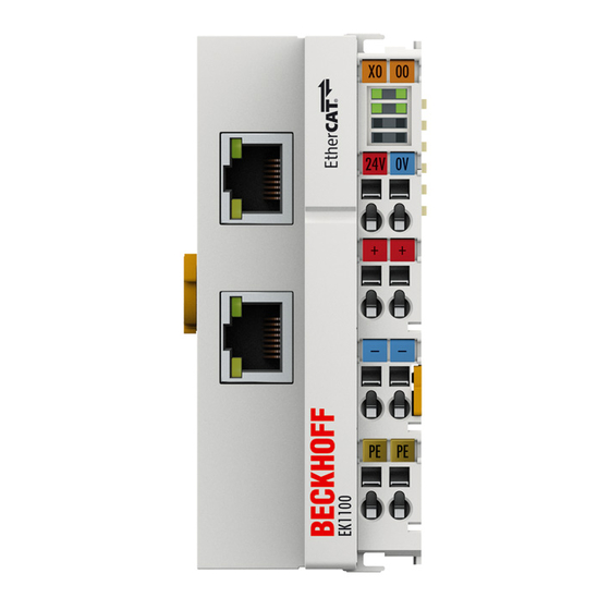
EK1101 - Introduction EK1101 EtherCAT coupler with ID switch The EK1101 coupler connects the EtherCAT Device Protocol with the EtherCAT Terminals (ELxxxx/ESxxxx/ EMxxxx). One station consists of a coupler, any number of EtherCAT Terminals and a bus end terminal, e.g. - Page 18 EK1101-0080 - Introduction EK1101-0080 EtherCAT coupler with ID switch The EK1101-0080 EtherCAT coupler with Fast Hot Connect technology is an extension of the EK1101 coupler. Hot Connect is an EtherCAT feature for changing topologies through direct coupling or uncoupling during operation.
- Page 19 Product overview 2.2.2.3 EK1101, EK1101-0080 - Technical data Technical data EK1101 EK1101-0080 Task within the EtherCAT system Coupling of EtherCAT Terminals Coupling of EtherCAT Terminals (ELxxxx) to 100BASE-TX (ELxxxx) to 100BASE-TX EtherCAT networks EtherCAT networks, Fast Hot Connect technology Number of EtherCAT Terminals...
-
Page 20: Fig. 10 Identification Of Fhc Port At Ek1122-0080 And Ek1101-0080
Product overview Fig. 10: Identification of FHC port at EK1122-0080 and EK1101-0080 • Standard EtherCAT devices may not be connected to Fast Hot Connect ports. This is to be ensured by measures on the application side, which is easy to implement by means of the topology change that is usually carried out mechanically in such applications. -
Page 21: Fig. 12 Configuration Of A Fast Hot Connect Group
Product overview Configuration The configuration of Fast Hot Connect groups in the TwinCAT System Manager takes place in exactly the same way as Hot Connect groups, specifying the associated group ID. Fig. 12: Configuration of a Fast Hot Connect group Corresponding Fast Hot Connect ports are marked red in the TwinCAT System Manager. Fig. 13: Marking in the TwinCAT System Manager A configuration of FHC groups is possible only if at least 1 corresponding junction is present e.g. -
Page 22: Coupler With M8 Connection
Product overview Distributed Clocks If no Distributed Clocks functions are used, this is visible in the master settings by the absence of "DC in use": Fig. 14: DC master setting This setting is automatically selected by the System Manager if there are no EtherCAT slaves in the configuration in which Distributed Clocks is activated. - Page 23 Product overview EtherCAT coupler EK1100-0008 (M8 connection) The EK1100-0008 coupler connects EtherCAT with the EtherCAT Terminals (ELxxxx/ESxxxx). One station consists of a coupler EK1100-0008, any number of EtherCAT Terminals and a bus end terminal. The coupler converts the telegrams from Ethernet 100BASE-TX to E-bus signal representation. Compared to EK1100 the EK1100-0008 has two M8 sockets instead of two RJ45 sockets, compatible to the ones of the EtherCAT-Boxes.
- Page 24 Product overview 2.3.1.2 EK1100-0008 - Technical data Technical data EK1100-0008 Task within the EtherCAT system Coupling of EtherCAT Terminals (ELxxxx) to 100BASE-TX EtherCAT networks Number of EtherCAT Terminals up to 65535 in the overall system Transmission medium at least EtherCAT CAT-5 cable Cable length between two Bus Couplers max.
-
Page 25: Coupler With Optical Fiber Connection
Product overview Coupler with optical fiber connection 2.4.1 EK1501 2.4.1.1 EK1501 - Introduction EK1501 EtherCAT coupler with ID switch, multimode optical fiber connection The EK1501 coupler connects the EtherCAT Device Protocol with the EtherCAT Terminals (ELxxxx/ESxxxx/ EMxxxx). One station consists of a coupler, any number of EtherCAT Terminals and a bus end terminal, e.g. EL9011. - Page 26 Product overview • if the EtherCAT master supports HotConnect, then an I/O group can be adopted dynamically into the EtherCAT communication. This group can then be located at any position within the EtherCAT network. Variable topologies are therefore easily implementable. Quick links •...
-
Page 27: Ek1501-0010
Product overview 2.4.2 EK1501-0010 2.4.2.1 EK1501-0010 - Introduction EK1501-0010 EtherCAT coupler with ID switch, single-mode optical fiber connection The EK1501-0010 coupler differs from the EK1501 only in the transceiver used. Transmission ranges of up to 20 km can be attained with the single-mode technique using appropriate optical fiber cables. An attenuation budget of 10 dBm is available between the EK1501-0010 and the associated EK1521-0010 branch. - Page 28 Product overview 2.4.2.2 EK1501-0010 - Technical data Technical data EK1501-0010 Task within the EtherCAT system Coupling of EtherCAT Terminals (ELxxxx) to 100BASE-FX EtherCAT networks Number of EtherCAT Terminals up to 65535 in the overall system Number of peripheral signals max. 4.2 GB addressable IO points Transmission medium Single mode glass fiber (SM) Cable length between two Bus Couplers...
-
Page 29: Coupler With Pof Connection
Product overview Coupler with POF connection 2.5.1 EK1541 2.5.1.1 EK1541 - Introduction EK1541 EtherCAT coupler with ID switch, POF connection The EK1541 Coupler connects EtherCAT with the EtherCAT Terminals (ELxxxx). A station consists of an EK1541 coupler, any number of EtherCAT Terminals, an EL9011 bus end cap or an EK1110 EtherCAT extender. - Page 30 Product overview • Diagnostic LEDs [} 66] 2.5.1.2 EK1541 - Technical data Technical data EK1541 Task within the EtherCAT system Coupling of EtherCAT Terminals (ELxxxx) to 100BASE-FX EtherCAT POF networks Number of EtherCAT Terminals up to 65534 in the overall system Number of peripheral signals max.
-
Page 31: Basics
The following figure shows the direction of data flow in a fully connected EK1100 (or EK1100-0008) as an example: Fig. 15: Example: EK1100 / EK1100-0008 EtherCAT coupler with 3 ports The port assignment in the case of the EK1101, EK1501 and EK1501-0010, EK1814 applies accordingly. EK110x, EK15xx Version: 3.6... -
Page 32: Fig. 16 Internal And External Port Assignment For Bus Coupler Ek1100 And Ek1100-0008
Basics Fig. 16: Internal and external port assignment for Bus Coupler EK1100 and EK1100-0008 Frame processing sequence The EtherCAT frame arriving at the EtherCAT signal input is passed on by Port 0 (A) to the EtherCAT processing unit. • The EtherCAT frame arrives at Port 1 (B) and the data frame departs via Port 1 (B) to the following slave in the EtherCAT terminal network (if a slave is connected there and reports ‘Link’). -
Page 33: Ethercat State Machine
Basics EtherCAT State Machine The state of the EtherCAT slave is controlled via the EtherCAT State Machine (ESM). Depending upon the state, different functions are accessible or executable in the EtherCAT slave. Specific commands must be sent by the EtherCAT master to the device in each state, particularly during the bootup of the slave. A distinction is made between the following states: •... -
Page 34: Coe - Interface: Notes
CoE - Interface: notes This device has no CoE. Detailed information on the CoE interface can be found in the EtherCAT system documentation on the Beckhoff website. EKxxxx - Optional Distributed Clocks support Basic principles Distributed Clocks (DC) The EtherCAT Distributed Clocks system comprises local clocks that are integrated in the EtherCAT slaves and are synchronized by the EtherCAT master via special datagrams. -
Page 35: Fig. 19 Advanced Distributed Clocks Settings In The Ethercat Master
01: xxxx01yy CU1128 from CU1128-0000-0000 from firmware 00: xxxx00yy EK1100 from EK1100-0000-0017 from firmware 06: xxxx06yy EK1101 from EK1101-0000-0017 from firmware 01: xxxx01yy EK1501 from EK1501-0000-0017 from firmware 01: xxxx01yy EK1501-0010 from EK1501-0010-0017 from firmware 02: xxxx02yy EK1122... -
Page 36: Fig. 20 Twincat Setting For Using This Component As Reference Clock
Basics Fig. 20: TwinCAT setting for using this component as reference clock Activation of Distributed Clocks support The (synchronization) procedure described here is only successful for the components de- scribed above. The checkboxes can be set for other components, too, although the hard- Note ware does not support this function, unless specified in the respective documentation. -
Page 37: Mounting And Wiring
Each assembly must be terminated at the right hand end with an EL9011 bus end cap, to ensure the protection class and ESD protection. Fig. 21: Spring contacts of the Beckhoff I/O components Installation on mounting rails Risk of electric shock and damage of device! -
Page 38: Fig. 22 Attaching On Mounting Rail
Mounting and wiring Assembly Fig. 22: Attaching on mounting rail The Bus Coupler and Bus Terminals are attached to commercially available 35 mm mounting rails (DIN rails according to EN 60715) by applying slight pressure: 1. First attach the Fieldbus Coupler to the mounting rail. 2. -
Page 39: Fig. 23 Disassembling Of Terminal
Mounting and wiring Disassembly Fig. 23: Disassembling of terminal Each terminal is secured by a lock on the mounting rail, which must be released for disassembly: 1. Pull the terminal by its orange-colored lugs approximately 1 cm away from the mounting rail. In doing so for this terminal the mounting rail lock is released automatically and you can pull the terminal out of the bus terminal block easily without excessive force. -
Page 40: Installation Instructions For Enhanced Mechanical Load Capacity
Mounting and wiring Fig. 24: Power contact on left side Possible damage of the device Note that, for reasons of electromagnetic compatibility, the PE contacts are capacitatively coupled to the mounting rail. This may lead to incorrect results during insulation testing or Attention to damage on the terminal (e.g. - Page 41 Mounting and wiring Additional installation instructions For terminals with enhanced mechanical load capacity, the following additional installation instructions apply: • The enhanced mechanical load capacity is valid for all permissible installation positions • Use a mounting rail according to EN 60715 TH35-15 •...
-
Page 42: Installation Positions
Mounting and wiring Installation positions Constraints regarding installation position and operating temperature range Please refer to the technical data for a terminal to ascertain whether any restrictions re- garding the installation position and/or the operating temperature range have been speci- Attention fied. -
Page 43: Connection System
Mounting and wiring Fig. 26: Other installation positions Connection system Risk of electric shock and damage of device! Bring the bus terminal system into a safe, powered down state before starting installation, disassembly or wiring of the Bus Terminals! WARNING Overview The Bus Terminal system offers different connection options for optimum adaptation to the respective application: •... -
Page 44: Fig. 27 Standard Wiring
Mounting and wiring Standard wiring (ELxxxx / KLxxxx) Fig. 27: Standard wiring The terminals of ELxxxx and KLxxxx series have been tried and tested for years. They feature integrated screwless spring force technology for fast and simple assembly. Pluggable wiring (ESxxxx / KSxxxx) Fig. 28: Pluggable wiring The terminals of ESxxxx and KSxxxx series feature a pluggable connection level. -
Page 45: Wiring
Mounting and wiring Wiring HD Terminals The High Density (HD) Terminals of the ELx8xx and KLx8xx series doesn't support plug- gable wiring. Note Ultrasonically "bonded" (ultrasonically welded) conductors Ultrasonically “bonded" conductors It is also possible to connect the Standard and High Density Terminals with ultrasonically "bonded"... -
Page 46: Ethercat Cabling - Wire-Bound
Due to automatic cable detection (auto-crossing) symmetric (1:1) or cross-over cables can be used between EtherCAT devices from Beckhoff. Recommended cables Suitable cables for the connection of EtherCAT devices can be found on the Beckhoff web- site! Note E-Bus supply A bus coupler can supply the EL terminals attached to it with the E-bus system voltage of 5 V;... -
Page 47: M8 Connector Cabling
A list of the EtherCAT cable, power cable, sensor cable, Ethernet-/EtherCAT connectors and the field assembled connectors can be found at the following link: http://download.beckhoff.com/download/ document/catalog/main_catalog/english/Beckhoff_EtherCAT-Box-Accessories.pdf You can find the corresponding data sheets at the following link: http://beckhoff.de/english/fieldbus_box/ data_sheets.htm?id=69033899254355 EtherCAT cable Fig. 32: ZK1090-3131-0xxx... - Page 48 "Recommendations for the design of the infrastructure for EtherCAT/Ethernet", that is avail- Note able for download at www.Beckhoff.com. EtherCAT uses 4 wires for signal transfer. Due to automatic cable detection (auto-crossing) symmetric (1:1) or cross-over cables can be used between EtherCAT devices from Beckhoff.
-
Page 49: Nut Torque For Connectors
Mounting and wiring Nut torque for connectors Fig. 33: X1 and X2 of EK1100-0008 For usage of the EtherCAT connectors M8 of EK1100-0008 the following have to be noticed: M8 connectors It is recommended to pull the M8 connectors tight with a nut torque of 0.4 Nm. When using the torque control screwdriver ZB8800 is also a max. -
Page 50: Power Supply, Potential Groups
Mounting and wiring 4.10 Power supply, potential groups Bus Coupler power supply The Bus Couplers require a 24 V DC supply for their operation. The connection is made by means of the upper spring-loaded terminals labelled 24 V and 0 V. The supply voltage is used by the Bus Coupler electronics and for direct voltage generation for the E-bus. -
Page 51: Fig. 36 Gnd Concept Ekxxxx
Mounting and wiring GND concept Fig. 36: GND concept EKxxxx Fuse protection Coupler supply, fuse 1: depending on the required current consumption and hence the configured terminals typical max. 1 A Power contacts, fuse 2: permitted max. 10 A (slow-blow) The coupler electronics and the power contacts can be supplied together from the same source. In this case the fuse should be dimensioned for 10 A max. -
Page 52: Mounting Of Passive Terminals
2 Passive Terminals! Examples for mounting passive terminals (highlighted) Fig. 37: Correct configuration Fig. 38: Incorrect configuration 4.12 UL notice Application Beckhoff EtherCAT modules are intended for use with Beckhoff’s UL Listed EtherCAT Sys- tem only. Version: 3.6 EK110x, EK15xx... - Page 53 Mounting and wiring Examination For cULus examination, the Beckhoff I/O System has only been investigated for risk of fire and electrical shock (in accordance with UL508 and CSA C22.2 No. 142). For devices with Ethernet connectors Not for connection to telecommunication circuits.
-
Page 54: Atex - Special Conditions (Extended Temperature Range)
• EN 60079-0:2012+A11:2013 • EN 60079-15:2010 Marking The Beckhoff fieldbus components with extended temperature range (ET) certified for potentially explosive areas bear the following marking: II 3G KEMA 10ATEX0075 X Ex nA IIC T4 Gc Ta: -25 … 60°C II 3G KEMA 10ATEX0075 X Ex nC IIC T4 Gc Ta: -25 … 60°C Version: 3.6... -
Page 55: Atex Documentation
Notes about operation of the Beckhoff terminal systems in potentially explo- sive areas (ATEX) Pay also attention to the continuative documentation Note Notes about operation of the Beckhoff terminal systems in potentially explosive areas (ATEX) that is available in the download area of the Beckhoff homepage http:\\www.beckhoff.com! EK110x, EK15xx... -
Page 56: Commissioning/Application Notes
Commissioning/application notes Commissioning/application notes Configuration overview More detailed information on the configuration settings can be found in the EtherCAT system documentation on the Beckhoff website. Application notes 5.2.1 Optical fiber application notes Fig. 39: EK1501 5.2.1.1 Notes on suitable optical fiber cables General information on optical fiber types Optical fiber are available as multimode and single mode types with different step and graded indices. - Page 57 Commissioning/application notes Single mode Single-mode fibers have a very thin core (9 µm) and therefore conduct only a single mode of the light used, with high signal quality and virtually without mode dispersion. They are only available as step index fibers. Due to the high signal quality they are suitable for large transmission bandwidths >...
- Page 58 Commissioning/application notes Installation notes • permitted bending radius • permitted tensile strength Note • sensitivity of the exposed contact ends Further information can be found in the following documents: • ITU recommendation ITU-T G.651 - G.655 • EN 50173:2002 • EN 60793-2 Connecting and releasing the optical fiber cable at the junction Risk of damage to the cable! To disconnect the optical fiber cable always pull the connector to release the locking mech-...
-
Page 59: Pof Application Notes
Commissioning/application notes Use of blind plugs To protect the transceiver from environmental influences, unused connection socket should be sealed with the blind plugs provided! Note Figure: Blind plugs in unused sockets 5.2.2 POF application notes Fig. 40: EK1541 5.2.2.1 Notes regarding suitable POF cables General information about POF cables The standard polymer fiber is 1 mm thick and consists of a 0.98 mm thick core made of polymethyl methacrylate (PMMA) as well as a thin sheath. -
Page 60: Fig. 41 Latching Lug With Release Catch On The Pof Duplex Plug
[} 62] (Versatile Link Duplex connectors) in conjunction with a duplex polymer fiber with Note an outside diameter of 2 x 2.2 mm (Z1190), which are available from Beckhoff. Installation notes • permissible bending radius (in general r ≥ 25 mm, refer to the manufacturer’s data!) •... - Page 61 Commissioning/application notes TX / Rx channel assignment During cable assembly [} 62] note the assignment of the optical channels in the connec- tion sockets. In the EK1541 the light-emitting transmitter channel (Tx) is the lower outlet in Attention the connection sockets. Figure: Transmitter channels in the EK1541 Be sure to observe the safety instructions [} 71] for class 1 lasers! Use of blind plugs...
-
Page 62: Notes Regarding Assembly Of Pof Cables With The Connector Set Zs1090-0008
Notes regarding assembly of POF cables with the connector set ZS1090-0008 Fig. 42: Duplex connector set ZS1090-0008 The duplex connector set ZS1090-0008 from Beckhoff consists of 10 duplex Versatile Link connectors and several sheets of abrasive paper and polishing paper. Step-by-step instructions for assembling the POF cable The following step-by-step guide describes the correct assembly of a POF cable with a Versatile Link duplex connector. - Page 63 Commissioning/application notes 2. Attaching the connector Push the two cable ends into the connector and the connector back until it stops. The fibers should now protrude no more than 1.5 mm from the front openings. Close the connector by folding the upper and lower halves together until they engage. Fig. 44: Cable inserted in the connector Fig. 45: Closed connector When inserting the wires into the connector ensure the optical channels are crossed (Tx1 →...
- Page 64 Commissioning/application notes 3. Grinding and polishing Any fibers protruding more than 1.5 mm from the connector should be shortened with a cutter knife or a pair of scissors. Now push the connector fully into the sanding gauge, so that the ends to be polished protrude from the lower side.
- Page 65 Commissioning/application notes Fig. 49: Fine-polished fibers in the connector EK110x, EK15xx Version: 3.6...
-
Page 66: Error Handling And Diagnostics
Error handling and diagnostics Error handling and diagnostics Diagnostic LEDs Diagnostic LEDs EK1100, EK1100-0008 Fig. 50: Diagnostic LEDs EK1100, EK1100-0008 LEDs for power supply diagnostics Display State Description green off No operating voltage present at the Bus Coupler 24 V operating voltage present at the Bus Coupler green off No power supply present at the power contacts 24 V... - Page 67 Error handling and diagnostics Diagnostic LEDs EK1101-xxxx Fig. 51: Diagnostic LEDs EK1101-xxxx LEDs for power supply diagnostics Display State Description green off No operating voltage present at the Bus Coupler 24 V operating voltage present at the Bus Coupler green off No power supply present at the power contacts 24 V...
- Page 68 Error handling and diagnostics Diagnostic LEDs EK1501 Fig. 52: Diagnostic LEDs for Bus Coupler EK1501 LEDs for power supply diagnostics Display State Description green off No operating voltage present at the Bus Coupler 24 V operating voltage present at the Bus Coupler green off No power supply present at the power contacts 24 V...
- Page 69 Error handling and diagnostics Diagnostic LEDs EK1501-0010 Fig. 53: Diagnostic LEDs for Bus Coupler EK1501-0010 LEDs for power supply diagnostics Display State Description green off No operating voltage present at the Bus Coupler 24 V operating voltage present at the Bus Coupler green off No power supply present at the power contacts 24 V...
- Page 70 Error handling and diagnostics Diagnostic LEDs EK1541 Fig. 54: Diagnostic LEDs Bus Coupler EK1541 LEDs for power supply diagnostics Display State Description green off No operating voltage present at the Bus Coupler 24 V operating voltage present at the Bus Coupler green off No power supply present at the power contacts 24 V power supply present at the power contacts...
-
Page 71: Appendix
The EK110x and EK15xx Couplers have no firmware. Firmware Update EL/ES/EM/EPxxxx This section describes the device update for Beckhoff EtherCAT slaves from the EL/ES, EM, EK and EP series. A firmware update should only be carried out after consultation with Beckhoff support. -
Page 72: Device Description Esi File/Xml
Appendix Customers can access the data via the EtherCAT fieldbus and its communication mechanisms. Acyclic mailbox communication or register access to the ESC is used for updating or reading of these data. The TwinCAT System Manager offers mechanisms for programming all 3 parts with new data, if the slave is set up for this purpose. - Page 73 Corresponding updates Note should only be carried out in consultation with Beckhoff support. Display of ESI slave identifier The simplest way to ascertain compliance of configured and actual device description is to scan the EtherCAT boxes in TwinCAT mode Config/FreeRun: Fig. 56: Scan the subordinate field by right-clicking on the EtherCAT device in Config/FreeRun mode...
- Page 74 Appendix Fig. 57: Configuration is identical otherwise a change dialog appears for entering the actual data in the configuration. Fig. 58: Change dialog In this example in Fig. Change dialog, an EL3201-0000-0017 was found, while an EL3201-0000-0016 was configured. In this case the configuration can be adapted with the Copy Before button. The Extended Information checkbox must be set in order to display the revision.
-
Page 75: Firmware Explanation
7.4.2 Firmware explanation Determining the firmware version Determining the version on laser inscription Beckhoff EtherCAT slaves feature serial numbers applied by laser. The serial number has the following structure: KK YY FF HH EK110x, EK15xx Version: 3.6... -
Page 76: Updating Controller Firmware *.Efw
This CoE directory can only be displayed if a slave is connected and operational. • offline: The EtherCAT Slave Information ESI/XML may contain the default content of the CoE. This CoE directory can only be displayed if it is included in the ESI (e.g. "Beckhoff EL5xxx.xml"). - Page 77 Switch to the Online tab to update the controller firmware of a slave, see Fig. Firmware Update. Fig. 62: Firmware Update Proceed as follows, unless instructed otherwise by Beckhoff support. Valid for TwinCAT 2 and 3 as EtherCAT master. • Switch TwinCAT system to ConfigMode/FreeRun with cycle time >= 1 ms (default in ConfigMode is 4 ms).
-
Page 78: Fpga Firmware *.Rbf
Appendix • Switch slave to BOOTSTRAP • Check the current status (B, C) • Download the new *efw file (wait until it ends). A pass word will not be neccessary usually. • After the download switch to INIT, then PreOP •... - Page 79 Appendix Fig. 63: FPGA firmware version definition If the column Reg:0002 is not displayed, right-click the table header and select Properties in the context menu. Fig. 64: Context menu Properties The Advanced Settings dialog appears where the columns to be displayed can be selected. Under Diagnosis/Online View select the '0002 ETxxxx Build' check box in order to activate the FPGA firmware version display.
- Page 80 Older firmware versions can only be updated by the manufacturer! Updating an EtherCAT device The following sequence order have to be met if no other specifications are given (e.g. by the Beckhoff support): • Switch TwinCAT system to ConfigMode/FreeRun with cycle time >= 1 ms (default in ConfigMode is 4 ms).
- Page 81 Appendix • In the TwinCAT System Manager select the terminal for which the FPGA firmware is to be updated (in the example: Terminal 5: EL5001) and click the Advanced Settings button in the EtherCAT tab: • The Advanced Settings dialog appears. Under ESC Access/E²PROM/FPGA click on Write FPGA button: EK110x, EK15xx Version: 3.6...
-
Page 82: Simultaneous Updating Of Several Ethercat Devices
Appendix • Select the file (*.rbf) with the new FPGA firmware, and transfer it to the EtherCAT device: • Wait until download ends • Switch slave current less for a short time (don't pull under voltage!). In order to activate the new FPGA firmware a restart (switching the power supply off and on again) of the EtherCAT device is required. -
Page 83: Support And Service
Beckhoff's branch offices and representatives Please contact your Beckhoff branch office or representative for local support and service on Beckhoff products! The addresses of Beckhoff's branch offices and representatives round the world can be found on her internet pages: http://www.beckhoff.com You will also find further documentation for Beckhoff components there. - Page 84 ELM3604-0002 terminal with ID number (QR code) 100001051 and unique serial number 44160201............................. Fig. 9 EtherCAT coupler communication diagram ................. Fig. 10 Identification of FHC port at EK1122-0080 and EK1101-0080 ............ Fig. 11 Recommended combination of Ethernet ports ................Fig. 12 Configuration of a Fast Hot Connect group .................
- Page 85 Fig. 49 Fine-polished fibers in the connector................... Fig. 50 Diagnostic LEDs EK1100, EK1100-0008 ..................Fig. 51 Diagnostic LEDs EK1101-xxxx ....................Fig. 52 Diagnostic LEDs for Bus Coupler EK1501 .................. Fig. 53 Diagnostic LEDs for Bus Coupler EK1501-0010 ................. Fig. 54 Diagnostic LEDs Bus Coupler EK1541..................
Need help?
Do you have a question about the EK1101 and is the answer not in the manual?
Questions and answers