Table of Contents
Advertisement
Advertisement
Table of Contents

Related Manuals for ABB UMC100-FBP


Summary of Contents for ABB UMC100-FBP
- Page 1 Technical Description Universal Motor Controller UMC100-FBP...
- Page 2 Device driver technology for field devices. Specified from the FDT group. NC / NO Normall closed / Normally open FieldBusPlug is the name for a group of products which allows to connect ABB low voltage control products to different fieldbusses. Related Documents Technical Documentation Document No.
-
Page 3: Table Of Contents
Compatibility to UMC22 ........................10 Description of Components ......................11 2 Installation ............................17 Assembly and Disassembly of UMC100-FBP and IO Modules ............17 Connecting the IO Modules DX111 and DX122 ................17 Wiring DX1xx Inputs and Outputs ....................18 Connecting the VI15x Voltage Module .....................19 Wiring VI15x Inputs and Outputs ......................20... - Page 4 Universal Motor Controller UMC100-FBP Technical Description Using the Digital UMC Inputs ......................66 Control Function Transparent ......................69 Control Function Overload Relay ......................71 Control Function Direct Starter (DOL) ....................73 Control Function Reversing Starter (REV)..................76 Control Function Star-Delta Starter ....................79 Control Function Pole-Changing Starter ..................82 Control Function Actuator 1 - 4 ......................85...
- Page 5 Universal Motor Controller UMC100-FBP Technical Description Motor Management Parameters .....................120 Protection Parameters ........................125 Communication Parameters ......................129 IO Module Parameters ........................129 UMC Display Parameters .......................133 Function Block Related Parameters ....................134 All Parameters Sorted by Parameter Number ................135 All Parameters Sorted Alphabetically .....................137 A2 Circuit Diagrams with Emergency Stop Function ................139...
- Page 6 This manual describes the configuration tool (Device Type Manager) that can be used to configure and moni- tor the UMC100 and also other ABB control products like UMC22, softstarters and circuit breakers. It is based on the standardised FDT/DTM technology.
-
Page 7: New Features In Comparison To Preceeding Versions
To use the new features via fieldbus new fieldbus device description files have to be used. Therefore updated GSD and EDS files are available on the ABB web site. See section A1 for details. FieldBusPlug / Issue: 03.2012... - Page 8 Universal Motor Controller UMC100-FBP Technical Description UMC100-FBP - 8 - FieldBusPlug / Issue: 03.2012...
-
Page 9: System Overview
Motor Management, Inputs and Outputs • The UMC100-FBP provides six digital inputs, three relay outputs and one 24 V output. Therefore a wide number of control functions can be covered from the base device. • If further inputs or outputs are needed, the basic device can be expanded with an expansion module. -
Page 10: Compatibility To Umc22
Universal Motor Controller UMC100-FBP Technical Description Metering, Monitoring and Diagnosis • Rapid, comprehensive diagnostics and operating status information is available on the UMC100 itself (LEDs), on the LCD panel (clear text messages), via fieldbus or on a laptop connected directly or via bus to the UMC. -
Page 11: Description Of Components
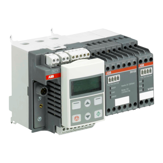
Universal Motor Controller UMC100-FBP Technical Description Description of Components UMC100-FBP The following diagram shows the terminals, monitoring and operating elements of the UMC100-FBP Current path (for measuring the motor current) Connecting terminals for PTC sensors Connecting terminals for the relay outputs... - Page 12 F u n ction B u s) P ane l) Interface Predefined or User-Defined Function Block Model Overview of the major building blocks of UMC100-FBP and the data flow among them. UMC100-FBP - 12 - FieldBusPlug / Issue: 03.2012...
- Page 13 Universal Motor Controller UMC100-FBP Technical Description DX111-FBP The DX111-FBP expands the input and output channels of the UMC100. It provides eight digital inputs for 24 V DC, four relay outputs and a current output to drive an analogue instrument. The following diagram shows the terminals and monitoring elements of the DX111-FBP module.
- Page 14 Universal Motor Controller UMC100-FBP Technical Description VI150-FBP The VI150-FBP adds voltage and power protection functions to the UMC-FBP. It provides three voltage inputs with a nominal range from 110 V AC - 690 V AC and one relay output. The module can be used with grounded systems only (e.g. TN-C / TN-S systems according to IEC 60364).
- Page 15 Technical Description Configuration Tool Asset Vision Basic is the tool to configure the UMC100-FBP via a Laptop. Asset Vision Basic is jointly used between ABB Instrumentation and ABB Control Products. Therefore it enables a wide range of ABB products to be configured such as motor controllers, soft starters, flow meters and many more.
- Page 16 Universal Motor Controller UMC100-FBP Technical Description UMC100-PAN LCD Panel The Control Panel UMC100-PAN is an accessory for the UMC100 and can be used for monitoring, control and parameterisation of the UMC100. It can be directly plugged on the UMC100 or mounted separately on the panel door using the mounting kit.
-
Page 17: Installation
UMC100-FBP Technical Description 2 Installation Assembly and Disassembly of UMC100-FBP and IO Modules You can attach the UMC100 and the IO modules as follows: • Snap-on mounting onto a 35 mm standard mounting rail, without tools (UMC100 and IO devices) • Mounting via screws on a mounting plate (UMC100 only) -
Page 18: Wiring Dx1Xx Inputs And Outputs
Universal Motor Controller UMC100-FBP Technical Description Wiring DX1xx Inputs and Outputs The diagram below shows the block diagram and wiring for both the DX111 and the DX122 modules. The digital inputs are galvanically isolated. The common ground for the inputs 1DI0-4 must be connected to 1DIZ. -
Page 19: Connecting The Vi15X Voltage Module
Universal Motor Controller UMC100-FBP Technical Description Connecting the VI15x Voltage Module The modules VI150 and VI155 allows to measure the motor supply voltage, cosphi (power factor) and to calculate thereof the active power and other values. There are two module variants. The VI155 module can be used in grounded (TN) and ungrounded (IT) networks. -
Page 20: Wiring Vi15X Inputs And Outputs
Universal Motor Controller UMC100-FBP Technical Description Wiring VI15x Inputs and Outputs The diagram below shows the block diagram and wiring of both the VI150 and the VI155 modules. The relay output is a normally open contact and can be freely used. -
Page 21: Connecting Contactors
Use spark suppression for larger contactors and also interface relays to maintain the service life of the UMC100 internal relays. For interfacing contactors with peak current > 0.5 A (Types A50 and larger) use an interface relay as shown below. Actual ABB contactors - all currents for 230 V AC (Extract): Contactor type Inrush... - Page 22 (built in) DOC DO0 UMC100 Connection of contactors with peak currents > 0.5 A (ABB types A50 and larger) to the UMC100-FBP. For checkback the auxiliary contact of the main contactor has to be used! UMC100-FBP - 22 -...
-
Page 23: Motor Wiring
Universal Motor Controller UMC100-FBP Technical Description Motor Wiring Have a look at the wiring of the motor to set the correct nominal current I for perfect motor protection. Example: For inner delta wiring the parameter Current Factor can be changed to 1.73 to display the actual currents on the Control Panel and in the control system. -
Page 24: Connecting External Current Transformers (Cts)
For currents up to 850 A, space saving combinations are recommended. Korc Terminals Korc Klemmen UMC100 READY MOT .O N FAUL T Rela y 230V AC Inputs Powe r 24VDC Wiring schema when using ABB Korc current transformers. UMC100-FBP - 24 - FieldBusPlug / Issue: 03.2012... - Page 25 Related parameter: Current Factor, I Operation Details for Motors with Small Set Currents When using a UMC100-FBP in an environment with very strong magnetic fields and a small set current at the same time, the current measurement can deviate a few percent from the real current.
-
Page 26: Connecting The Umc100-Pan Lcd Panel
The UMC100-PAN can also be plugged directly on the UMC100 itself. Extension cable to the UMC100 The UMC100-PAN is incompatible with the UMC22-PAN and cannot be used with the UMC22-FBP but only with UMC100-FBP. UMC100-FBP - 26 - FieldBusPlug / Issue: 03.2012... -
Page 27: Using The Umc100 In A Profibus Dp Network
PROFIBUS DP-V0 and PROFIBUS DP-V1. To integrate the UMC100-FBP into a PROFIBUS network either the PDQ22-FBP or the PDP22-FBP FieldBusPlugs can be used. PDQ22-FBP allows to connect up to four UMC100s via one bus node. -
Page 28: Using The Umc100 In A Devicenet Network
Engineering Package PBE91-FBP.010x 1SAJ924091R010x.ZIP The ZIP file can be obtained from ABB’s web site (http://www.abb.de -> Control Products and Systems) or on the FBP System CD (2CDC 190 008 E04xx). Please ask your local sales office for it. The UMC100 can be parameterised using the GSD file. But due to parameter length limitations only the most important parameters can be configured with the GSD file... -
Page 29: Using The Umc100 In A Canopen Network
Besides the physical connection of a device to a CANopen line, the integration and engineering of the de- vices in the CANopen master is necessary. For that purpose an electronic data sheet is provided by ABB. In the CANopen world these electronic data sheets are called EDS files. Within these files all the proper- ties relevant for operating the slave are described (e.g. -
Page 30: Using The Umc100 In A Modbus Rtu Network
Universal Motor Controller UMC100-FBP Technical Description Using the UMC100 in a MODBUS RTU Network The MODICON Modbus® RTU protocol is a widely used network protocol based on the RS485 physi- cal layer. It is provided in many PLCs that do not offer any other fieldbus. To integrate the UMC100 into a Modbus network, use the MRP21-FBP FieldBusPlug. -
Page 31: Usage In Draw-Out Systems
Universal Motor Controller UMC100-FBP Technical Description Usage in Draw-Out Systems The withdrawable technique is often used in industries where the highest availability and shortest down- times are required. In the event of an error in a drawer, the replacement with a spare drawer shall be made as fast as possible. - Page 32 Universal Motor Controller UMC100-FBP Technical Description The following diagram shows the usage of the PDQ22 in a drawer system with the available accessories. Connection to drawer Shield Connection to UMC 1- 4 (4 x CDP16-FBP) from previous FieldBusPlug PDQ22-FBP to next...
-
Page 33: Commissioning
This chapter provides an overview of the required commissioning steps. For details about the single steps please consult the related chapters. Commissioning Steps To commission the UMC100-FBP, proceed as follows: A) Wiring Wiring and 24 V DC / 0 V connection: Hard wire with switch apparatus and other components acc. - Page 34 UMC100s connected to this line. This is recommended for larger PROFIBUS installations. For configuration via laptop use the ABB tool "Asset Vision Basic". It is jointly used by ABB Instrumentation and ABB Control Products. It is based on the FDT/DTM standard.
-
Page 35: Test Position
Universal Motor Controller UMC100-FBP Technical Description FieldBusPlug Interface Interface UTF21 Service Laptop 24 V DC PROFIBUS Master UMCwith FieldBusPlug PDP22 PDA11 PDA12 24 V DC 24 V DC 24 V DC PROFIBUS Cable DSUB9 / DSUB9 UTP22 Interface Connection of the Service - Laptop &... - Page 36 Universal Motor Controller UMC100-FBP Technical Description UMC100-FBP - 36 - FieldBusPlug / Issue: 03.2012...
-
Page 37: Configuring The Motor Protection Functions
Universal Motor Controller UMC100-FBP Technical Description 4 Configuring the Motor Protection Functions General Information The UMC provides comprehensive motor protection including phase failure detection, adjustable motor protection for stalled motors during startup or normal operation, configurable current limits to generate trips or warnings and many more. - Page 38 Universal Motor Controller UMC100-FBP Technical Description Protection functions can be either on or off. If switched on, they can trigger a protection trip or a warning (excluding the thermal overload which is always active and triggers a trip). For some functions an optional delay can be specified.
- Page 39 Universal Motor Controller UMC100-FBP Technical Description Electronic Overload Protection The UMC protects three-phase AC motors in compliance with IEC 60947-4-1. The tripping class can be set to class 5, 10, 20, 30 or 40. The advanced thermal motor model considers both the copper and iron parts of the motor thus providing the best protection of the motor.
- Page 40 Universal Motor Controller UMC100-FBP Technical Description Example of trip class selection: Select the trip class so that the motor is thermally protected, even when the rotor is stalled. This means that the tripping curve of a cold motor has to be below the coordination point I...
- Page 41 Universal Motor Controller UMC100-FBP Technical Description Cyclic motor operation modes Some applications require periodic start/operation/stop cycles. Setting up such applications requires care when selecting the cooling down times or defining the shortest possible start period. In the next diagram three successive start cycles are displayed. In each cycle the motor starts at 700% I This high load lasts for about 7 seconds.
- Page 42 Universal Motor Controller UMC100-FBP Technical Description Long Start, Locked Rotor Protection This function detects a long start situation which is caused from a locked rotor for example. The func- tion creates a trip if the motor current continuously exceeds a threshold for a configurable period of time.
- Page 43 Universal Motor Controller UMC100-FBP Technical Description High Current Protection This function is useful to protect the driven mechanical system from jams and excessive overloads caused by the equipment or the process. The high-current function signals a warning when the motor current exceeds a set threshold for a con- figurable period of time, after the motor start-up.
- Page 44 Universal Motor Controller UMC100-FBP Technical Description Low Current Protection The low current function is triggered when the motor current falls below a desired level. The function detects loss of suction for pumps, broken belt for conveyors, loss of airflow for fans, broken tools for ma- chines etc.
- Page 45 Universal Motor Controller UMC100-FBP Technical Description Phase Loss Protection (Current) This function protects motors against the extreme situation where a complete phase is lost. An unde- tected phase loss can cause motor damage because of the sudden rise of current in the two remaining phases.
- Page 46 Universal Motor Controller UMC100-FBP Technical Description Phase Sequence Protection Enable this protection function to prevent connected equipment from a wrong rotation direction e.g when driving a crusher or conveyor. If this protection function is active the motor wires must have a defined order which is from left to right.
-
Page 47: Earth Fault Protection
Universal Motor Controller UMC100-FBP Technical Description Earth Fault Protection The earth fault protection function protects the motor and the network against ground current flow. Earth faults are mainly caused due to ageing of the insulation, deterioration of insulation due to sustained or cyclic overloading, moisture or conductive dust. - Page 48 Universal Motor Controller UMC100-FBP Technical Description Protection based on internal Calculation The UMC can detect an earth fault by summing up the three phase currents without using an external current transformer. The internal earth fault detection function signals a warning when the earth fault current exceeds a set threshold for a configurable period of time, after the motor start-up.
-
Page 49: Thermistor (Ptc) Motor Protection Acc. To En 60947-8 (Type A Sensors)
Universal Motor Controller UMC100-FBP Technical Description Thermistor (PTC) Motor Protection acc. to EN 60947-8 (type A sensors) PTC thermistors are semiconductor elements with a very high positive temperature coefficient. They are embedded directly in the phase windings of the stator. In contrast to the thermal overload protection that responds to the load current, the thermistor protection responds to the change in thermistor resistance due to temperature change in the motor windings. -
Page 50: Voltage And Power Protection Functions
Universal Motor Controller UMC100-FBP Technical Description Voltage and Power Protection Functions This section describes the voltage based motor protection functions. The UMC100 together with the volt- age module VI150/VI155 continuously measures the motor supply voltage (line to line), the motor current and the phase angle between the current and voltage. - Page 51 Universal Motor Controller UMC100-FBP Technical Description Function Overview Protection Function When active Available Op- Automatic tions: Fault Reset Warning/Trip/ Possible Off/Other Overvoltage: The highest value of the Motor running Trip, Warning, Off three phases is above a given thresh- Motor stopped old.
-
Page 52: Total Harmonic Distortion
Universal Motor Controller UMC100-FBP Technical Description Voltage based Protection Functions The following block diagram provides an overview of the signal flow related to voltage supervision and protection. The different voltage protection functions are usually always active (also if the motor is in stop mode). - Page 53 Universal Motor Controller UMC100-FBP Technical Description Power Factor and Power Supervision The power factor and the active power are important values to detect underload or no-load situations in applications where a change of the load is not equally reflected in a change of the motor current (e.g.
- Page 54 Universal Motor Controller UMC100-FBP Technical Description The following block diagram shows the data flow of the power supervision in the UMC/VI15x and the generated signals. Disable > Voltage dip Load starting Load Motor start delay Running P high & warn delay P>P high...
-
Page 55: Voltage Dips, Load Shedding
Universal Motor Controller UMC100-FBP Technical Description Voltage Dips, Load Shedding Motors switched off during voltage dips or power failure can be restarted on power resumption sequen- tially to prevent simultaneous switch-on of the motors and thus prevent another mains failure on the network. - Page 56 Universal Motor Controller UMC100-FBP Technical Description Parameter Description Parameter Explanation Dip Duration If the voltage dip is longer than this time a 'Dip Duration' error is triggered. Dip Autorestart Window If the voltage recovers within this time the motor is not switched off - i.e.
- Page 57 Universal Motor Controller UMC100-FBP Technical Description Restart Level Level Auto- restart Dip Autorestart Window Delay Undervoltage situation UMC Relay Out DIP signal at digital input DIP Duration Case b: The low voltage situation takes longer than the configured 'Dip Autorestart Window' which means the UMC switches off the relay output.
- Page 58 Universal Motor Controller UMC100-FBP Technical Description Double DIPs Special handling can be activated if two dips occur within one second. Set parameter 'Dip Enable' to 'On + Rapid Cycle Lockout'. If within one second two low voltage situations occur, immediately after the start of the second low voltage situation the contactors are switched off.
-
Page 59: Configuring The Motor Management Functions
Universal Motor Controller UMC100-FBP Technical Description 5 Configuring the Motor Management Functions In this section you find the following information: • Introduction into the supported control stations and operation modes • How to start and stop the motor from the different control stations • Available control functions... - Page 60 Universal Motor Controller UMC100-FBP Technical Description Therefore the UMC enables start/stop commands to be individually released or blocked from a control station depending on modes. Three different modes are available named by their typical usage: Mode Default Behaviour Auto (Remote) In this operation mode the UMC accepts start commands from the DCS/PLC. To activate this control mode the "Auto Mode Bit"...
- Page 61 Universal Motor Controller UMC100-FBP Technical Description Example: The following requirements shall be fulfilled: • Switch S1 has the following positions: Remote/Local/Test Position/Off. • (Req. 1) If the switch is in position Local the UMC can only be controlled locally (digital inputs and LCD) but not started via bus.
- Page 62 Universal Motor Controller UMC100-FBP Technical Description Auto mode Finally it is necessary to configure from which control places the motor can be started in the different operation modes (Auto / Local ). The following parameters are set according to the requirements (Req 1, Req2, Req 5):...
- Page 63 Universal Motor Controller UMC100-FBP Technical Description Control Starter Stations Function (e.g. DOL) Digital Inputs Start Stop Panel Cyclic Bus Telegram Acyclic Telegram Super- vision Force Local 2 Mode enable Automode Fieldbus Selection Busfault Activating Inching Mode By default "pulses" are used to issue a start command. This means that a start input has to change its logic level to issue a start command - i.e.
-
Page 64: Limit The Number Of Starts
Universal Motor Controller UMC100-FBP Technical Description Emergency Start In some special cases a motor must be started even if the thermal overload protection would prevent the start (i.e. cooling time is still running). To allow the start in such situations the thermal memory of the UMC can be reset to cold state. - Page 65 Universal Motor Controller UMC100-FBP Technical Description Parameter combinations: Num Starts Allowed Num Starts Window Num Starts Pause Resulting Behaviour Function not active. (Default) > 0 > 0 > 0 Number of starts not limited but pause between starts active > 0 >...
-
Page 66: Checkback Monitoring
Universal Motor Controller UMC100-FBP Technical Description Checkback Monitoring The UMC can be parameterised to monitor that the motor was really started using a checkback signal. By default the actual motor current is monitored. But it is also possible to use an auxiliary contact mounted on the main contactor. - Page 67 Universal Motor Controller UMC100-FBP Technical Description The unchanged signal from the DI is always available for monitoring purposes (Input 1/2/3 status). Test Postion ≥1 ≥1 On Delay ≥1 Motor Stop Delayed ≥1 ≥1 External Fault 0 Input 0 Status Full On Delay ≥1...
- Page 68 Universal Motor Controller UMC100-FBP Technical Description Sample Application for using the Multifunction Inputs The following diagram shows how to realise a dry-pump protection application. When the motor is start- ing there is no pressure. It takes some time until the pressure reaches its normal value. In this example we assume that the pressure has to appear within 4 seconds, otherwise the pump can be destroyed.
-
Page 69: Control Function Transparent
Universal Motor Controller UMC100-FBP Technical Description Control Function Transparent The UMC100 parametrised with the control function 'Transparent' behaves like an I/O module with an integrated overload check. The outputs DO0 ... DO3 and the inputs DI0 ... DI5 are directly connected to the fieldbus and are independent of the overload status. - Page 70 Universal Motor Controller UMC100-FBP Technical Description Monitoring Data for Transparent Word Byte Bit 7 Bit 6 Bit 5 Bit 4 Bit 3 Bit 2 Bit1 Bit 0 Summary Summary Overload Warning Fault warning UMC100 UMC100 UMC100 UMC100 UMC100 UMC100 2, 3...
-
Page 71: Control Function Overload Relay
Universal Motor Controller UMC100-FBP Technical Description Control Function Overload Relay The UMC100 parameterised with the control function 'Overload relay' can be used to replace a standard overload relay. The outputs DO2 ... DO3 and the inputs DI0 ... DI5 are directly connected to the fieldbus and not used from the control function. - Page 72 Universal Motor Controller UMC100-FBP Technical Description Monitoring Data for Overload Relay Word Byte Bit 7 Bit 6 Bit 5 Bit 4 Bit 3 Bit 2 Bit1 Bit 0 Summary Summary Overload Warning Fault warning UMC100 UMC100 UMC100 UMC100 UMC100 UMC100...
-
Page 73: Control Function Direct Starter (Dol)
Universal Motor Controller UMC100-FBP Technical Description Control Function Direct Starter (DOL) Use this function in a feeder that requires a motor to start/stop in one direction of rotation. • Relay output DO0 is used from the control function. • Optionally DI0 can be used for contactor checkback supervision • Optionally DI4/DI5 can be used to start/stop the motor locally... - Page 74 Universal Motor Controller UMC100-FBP Technical Description Timing Diagram for Direct Starter Over- Fault End of load reset cooling time RUN FORWARD Commands (received telegram) FAULT RESET UMC internal FAULT UMC outputs Motor current / Check-back aux. contact RUN FORWARD Monitoring signals...
- Page 75 Universal Motor Controller UMC100-FBP Technical Description Monitoring Data for Direct Starter Word Byte Bit 7 Bit 6 Bit 5 Bit 4 Bit 3 Bit 2 Bit1 Bit 0 Summary Summary Local Overload Run For- Warning Fault Control warning ward UMC100...
-
Page 76: Control Function Reversing Starter (Rev)
Universal Motor Controller UMC100-FBP Technical Description Control Function Reversing Starter (REV) Use this function in a feeder that requires a motor to start/stop in two direction of rotation (forwards/back- wards). • Relay output DO0 is used by the control function to start the motor in a forward direction. - Page 77 Universal Motor Controller UMC100-FBP Technical Description Timing Diagram for Changing Direction reverse forward ignored reverse RUN FORWARD Commands (received RUN REVERSE telegram) DO0 (forward) UMC outputs DO1 (reverse) Motor current / Check-ack aux. contact RUN FORWARD RUN REVERSE Monitoring signals...
- Page 78 Universal Motor Controller UMC100-FBP Technical Description Monitoring Data for Reversing Starter Word Byte Bit 7 Bit 6 Bit 5 Bit 4 Bit 3 Bit 2 Bit1 Bit 0 Summary Summary Local Reverse Overload Warning Fault Control Lockout warning Forward Reverse...
-
Page 79: Control Function Star-Delta Starter
Universal Motor Controller UMC100-FBP Technical Description Control Function Star-Delta Starter Use this function in a feeder that requires to start/stop a motor in one direction of rotation including the time- or current-controlled transition from star to delta. • Relay output DO0 is used by the control function to control the star contactor • Relay output DO1 is used by the control function to control the delta contactor... - Page 80 Universal Motor Controller UMC100-FBP Technical Description Timing Diagram for Star-Delta Starter Start Stop RUN FORWARD Commands (received telegram) DO0 (star) YD starting time pause time ~ 20 ms DO1 (delta) outputs DO2 (main) Motor current / Checkback Aux. contact RUN FORWARD...
- Page 81 Universal Motor Controller UMC100-FBP Technical Description Monitoring Data for Star-Delta Starter Word Byte Bit 7 Bit 6 Bit 5 Bit 4 Bit 3 Bit 2 Bit1 Bit 0 Summary Summary Local Overload Warning Fault Control warning Forward UMC100 UMC100 UMC100...
-
Page 82: Control Function Pole-Changing Starter
Universal Motor Controller UMC100-FBP Technical Description Control Function Pole-Changing Starter Use this function in a feeder that requires a two-pole or dahlander motor to start-stop in one direction of rotation. • Relay output DO0 is used by the control function to start the motor at speed one • Relay output DO1 is used by the control function to start the motor at speed two... - Page 83 Universal Motor Controller UMC100-FBP Technical Description Dahlander Motor L1, L2, L3 Contactor (24VDC) Supply (e.g. 230VAC) K81=speed one K91=speed two K91a K91b 24VDC DOC DO0 UMC- UMC100 Fieldbus Plug 10 11 13 14 DI1 DI2 DI3 DI4 DI5 k91a k91b...
- Page 84 Universal Motor Controller UMC100-FBP Technical Description Monitoring Data for Pole-Changing Starter Word Byte Bit 7 Bit 6 Bit 5 Bit 4 Bit 3 Bit 2 Bit1 Bit 0 Summary Summary Local Overload Warning Fault Control warning Forward UMC100 UMC100 UMC100...
-
Page 85: Control Function Actuator 1 - 4
Universal Motor Controller UMC100-FBP Technical Description Control Function Actuator 1 - 4 Use this function in a feeder that requires the operation of an actuator that opens/closes e.g. a valve. Please note that the actuator operation mode is not able to keep a valve at a certain setpoint. - Page 86 Universal Motor Controller UMC100-FBP Technical Description Overview: Control function Open <-> Closed Torque open Limit open Limit closed Torque closed Actuator 1 Stop Stop Actuator 2 Stop Prepare Prepare Stop Actuator 3 Stop Prepare Stop Actuator 4 Stop Prepare Stop...
- Page 87 Universal Motor Controller UMC100-FBP Technical Description Actuator 2 Open and Closed position via torque and limit switches DI0: Preparation for Open limit motor off DI1: Preparation for Closed limit motor off Limit switches Torque DI3: - Motor off, start only in opposite direction...
- Page 88 Universal Motor Controller UMC100-FBP Technical Description Actuator 4 Open position via torque and limit switches, Closed posi- tion via limit switch only DI0: Preparation for Open limit motor off DI1: Motor off, start only in Open direction Limit switches Torque DI3: • Motor off if prepared for Open off, start only...
- Page 89 Universal Motor Controller UMC100-FBP Technical Description Monitoring Data for Actuator 1 - 4 Word Byte Bit 7 Bit 6 Bit 5 Bit 4 Bit 3 Bit 2 Bit1 Bit 0 Summary Summary Local Reverse Overload Opening Closing Warning Fault Control...
- Page 90 Universal Motor Controller UMC100-FBP Technical Description UMC100-FBP - 90 - FieldBusPlug / Issue: 03.2012...
-
Page 91: Configuring The Fieldbus Communication
4. The UMC100-FBP and the FieldBusPlug contain the same address: Operation and communication starts. 5. The UMC100-FBP and the FieldBusPlug contain different addresses (e.g. unintentional permutation when installing a drawer): The behaviour of the UMC100-FBP depends on the setting of the parameter Ad- dress check. FieldBusPlug / Issue: 03.2012... -
Page 92: Defining The Bus Fault Reaction
- Click "Fix" (right hot-key) to select the fieldbus plug bus address - After saving the corrected bus address the communication starts immediately - Both the FieldBusPlug and the UMC100-FBP store the adjusted address. Related Parameter: Address Check Defining the Bus Fault Reaction Depending on the application the UMC is used in you might configure the reaction to a bus fault in a dif-... -
Page 93: Ignore Block Parameters
Universal Motor Controller UMC100-FBP Technical Description Block parameters can be used to parameterise a device from within the PROFIBUS master using the GSD file. The PROFIBUS master then sends the parameters in one block (this where the name came from) to the device. - Page 94 Universal Motor Controller UMC100-FBP Technical Description UMC100-FBP - 94 - FieldBusPlug / Issue: 03.2012...
-
Page 95: Using Expansion Modules
Universal Motor Controller UMC100-FBP Technical Description 7 Using Expansion Modules In this chapter you learn how to use the UMC expansion modules. Expansion modules allow you to increase the number of usable inputs and outputs. For information on how to connect the IO modules to the UMC read the ‘Installation’... -
Page 96: Using A Voltage Module (Vi150/155)
Universal Motor Controller UMC100-FBP Technical Description Using the Analogue Output The analogue output can be used to drive an analogue instrument to e.g. display the motor current. It can work in the following modes: 4-20mA, 0-20mA, 0-10V Relevant Module Parameters: • DX1xx Enabled... -
Page 97: The Lcd Control Panel Umc100-Pan
Universal Motor Controller UMC100-FBP Technical Description 8 The LCD Control Panel UMC100-PAN Overview The UMC100-PAN provides a easy to use multi-language user interface for the UMC100. In this chapter you will find the following information: • menu structure • how to operate the UMC100 with the LCD panel • how to acknowledge faults... -
Page 98: Monitoring Status Information
Universal Motor Controller UMC100-FBP Technical Description Monitoring Status Information On the top level of the menu tree which is entered after powering on, several information masks show the overall status of the UMC and connected IO. To switch between the different masks, use the scroll up or scroll down keys. - Page 99 Universal Motor Controller UMC100-FBP Technical Description Masks on the top level and the main configuration menu masks. Main menu Main Configuration Menu From any menu point Feldbus 1: Motor Management address (right hotkey) (e.g. control function) from any menu point...
- Page 100 Universal Motor Controller UMC100-FBP Technical Description Motor Management Parameters Within this submenu all motor management related parameters can be configured. The diagram below shows the organisation of the different parameter masks in the menu tree. The parameters are described in details in the section "Parameters and Data Struc- tures on a Fieldbus->Parameter Organisation->...
- Page 101 Universal Motor Controller UMC100-FBP Technical Description Motor Protection Parameters Within this submenu all motor protection related parameters can be configured. The diagram below shows the organisation of the different parameter masks in the menu tree. The parameters are described in detail in the section "Parameters and Data Structures on a Fieldbus->Parameter Organisation->...
- Page 102 Universal Motor Controller UMC100-FBP Technical Description Communication Parameters Within this submenu all communication related parameters can be configured. The diagram below shows the organisation of the different parameter masks in the menu tree. The parameters are described in details in the section "Parameters and Data Structures on a Fieldbus->Parameter Organisation- >Communication Parameters".
- Page 103 Universal Motor Controller UMC100-FBP Technical Description Maintenance and Service Parameters/Actions Within this submenu all maintenance and service related parameters / actions can be configured. The figure below shows the organisation of the different parameter masks in the menu tree. Menu point 6.3.1 shows the list of errors and their occurrence in seconds since the start-up of the UMC.
-
Page 104: Adjusting Parameters
Universal Motor Controller UMC100-FBP Technical Description Adjusting Parameters Adjusting a Numerical Value This type of dialog allows a numerical value to be specified within the given limits. The single digits must be defined from right to left. If the last digit was reached the right hot key changes from 'Next' to 'Save'. - Page 105 Universal Motor Controller UMC100-FBP Technical Description Specifying a Text String This type of dialog allows a character string to be specified e.g. an error message. With the up/down keys you can scroll through the alphabet and several special characters. Pressing 'Next' selects the next charac- ter to edit.
-
Page 106: Starting And Stopping The Motor
Universal Motor Controller UMC100-FBP Technical Description Starting and Stopping the Motor If control via LCD panel was enabled, it is possible to start/stop the motor from the 'Control' menu which can be accessed from the top level menu when pressing the left hot key (Cntrl). Depending on the se- lected control function a list of possible start directions is displayed. - Page 107 Universal Motor Controller UMC100-FBP Technical Description Acknowledge a Fault If a fault is present the 'Cntrl' menu is replaced with the menu to acknowledge faults (top level menu, left hot key). While a fault is present it is not possible to enter the Motor Control menu until the fault has been acknowledged.
- Page 108 Universal Motor Controller UMC100-FBP Technical Description UMC100-FBP - 108 - FieldBusPlug / Issue: 03.2012...
-
Page 109: Error Handling, Maintenance And Service
Universal Motor Controller UMC100-FBP Technical Description 9 Error Handling, Maintenance and Service Within this chapter you will find the following information • Error handling of the UMC • Detailed explanation of all error and diagnosis messages • Functions related to maintenance and service Error Handling of the UMC When the UMC detects a fault condition the fault becomes latched. - Page 110 Universal Motor Controller UMC100-FBP Technical Description Indicator Code Source / Root Cause Possible Cause / Suggested Ac- tion Phase loss Supply side At least one phase current is below Load side the phase loss threshold Contactors Check for blown fuse...
- Page 111 Universal Motor Controller UMC100-FBP Technical Description Indicator Code Source / Root Cause Possible Cause / Suggested Ac- tion Earth fault (external or Load side electrical Connection between one or more internal sensor) above trip phases and ground threshold Check wiring / motor (isolation...
- Page 112 Universal Motor Controller UMC100-FBP Technical Description Indicator Code Source / Root Cause Possible Cause / Suggested Ac- tion Overload Power Load side mechanics The motor load is too high. Check if the load is blocked or tight. Voltage Out of Spec...
- Page 113 Universal Motor Controller UMC100-FBP Technical Description Indicator Code Source / Root Cause Possible Cause / Suggested Ac- tion CB relay 0 Wiring, Expected feedback from a contac- Contactors tor is missing after checkback time was over. Check wiring of auxiliary contact to the correct UMC input.
-
Page 114: Resetting Parameters To Factory Defaults
Universal Motor Controller UMC100-FBP Technical Description Indicator Code Source / Root Cause Possible Cause / Suggested Ac- tion PF below trip/warn level 120, Active power consumption Either the motor is idle (not loaded) of the motor is too low or the motor load is not connected because of a broken belt or a dry running pump etc. -
Page 115: Reading, Setting And Resetting Maintenance Counters
Universal Motor Controller UMC100-FBP Technical Description Reading, Setting and Resetting Maintenance Counters Preventive maintenance is the best way to ensure the long service life of any equipment. The UMC provides several counters which help to better plan maintenance activities or to track down an existing problem. -
Page 116: Dx1Xx / Vi15X Status Codes
No further user actions are required. Requesting Support If you need support we kindly ask you to contact your local ABB representative using the template provid- ed at the end of this manual. Check the Configuration The menu option "Changed parameters"... -
Page 117: A1 Parameters And Data Structures On A Fieldbus
Universal Motor Controller UMC100-FBP Technical Description A1 Parameters and Data Structures on a Fieldbus In the following chapter you find a detailed description of all UMC parameters, the format of the com- mand monitoring and diagnosis telegrams. Furthermore the information is provided of how the UMC data... - Page 118 Universal Motor Controller UMC100-FBP Technical Description Diagnosis Data Word Byte Bit 7 Bit 6 Bit 5 Bit 4 Bit 3 Bit 2 Bit1 Bit 0 Checkback PTC wiring PTC hot Pre- Locked Phase im- Phase Thermal missing failure waring rotor dur-...
-
Page 119: Accessing Data On Profibus
Universal Motor Controller UMC100-FBP Technical Description Accessing Data on PROFIBUS On PROFIBUS the device parameters, monitoring data and the command data size is described in the GSD file and mapped to the data telegrams cyclically exchanged between the PROFIBUS master and the UMC. -
Page 120: Parameter Organisation
Universal Motor Controller UMC100-FBP Technical Description Parameter Organisation The UMC parameters are described in groups reflecting the major function blocks of the UMC. The figures in braces (e.g. 1.1) provide the link the menu strucutre i.e. where it is displayed. - Page 121 Universal Motor Controller UMC100-FBP Technical Description Motor Management Parameters Continued Para- Parameter Description, Explanations Options meter just- Number able Checkback Selection of the checkback Contact DI0 (1), supervision method. Current (2), Simulation (3) Inching DI Enables inching (i.e. jogging) No (0),...
- Page 122 Universal Motor Controller UMC100-FBP Technical Description Motor Management Parameters Continued Para- Parameter Description, Explanations Options Adjustable meter Number Loc 2 start bus Allow the motor to be started No (0), cyclic via cyclic bus command in Yes (1) local mode 2...
- Page 123 Universal Motor Controller UMC100-FBP Technical Description Motor Management Parameters Continued Para- Parameter Description, Explanations Options Adjustable meter Number Invert control (ctrl) Inputs Inv DI start If inverted (Yes) the DI is nor- No (0), Yes (1) input mally closed. If not inverted (No) it is normally open.
- Page 124 Universal Motor Controller UMC100-FBP Technical Description Motor Management Parameters Continued Para- Parameter Description, Explanations Options Adjustable meter Number Emergency To allow start-ups even if the Off (0), On (1) Start thermal overload protection would prevent them. Fault auto Automatically reset of se-...
-
Page 125: Protection Parameters
Universal Motor Controller UMC100-FBP Technical Description Protection Parameters Para- Parameter Description, Explanations Options Adjust- meter Name able via Number Protection Parameters Setting I Nominal current of motor for speed 0.24...3200A in steps of 0.01A Default: 0.50A Unscaled: 24...320000 Example: A value of 24... - Page 126 Universal Motor Controller UMC100-FBP Technical Description Protection Parameters Continued Para- Parameter Description, Explanations Options Adjust- meter Name able via Number Thermal load If the thermal model reaches 20 ... 100 All ex- warning level the warning level a warning is cluding generated.
- Page 127 Universal Motor Controller UMC100-FBP Technical Description Protection Parameters Continued Para- Parameter Description, Explanations Options Adjust- meter Name able via Number Low curr trip Value in % of I/I . Below this va- 0...100% in steps of 5% level lue a trip is generated. A value Default: 0% of 0% disables the trip.
- Page 128 Universal Motor Controller UMC100-FBP Technical Description Protection Parameters Continued All exclu- Voltage Dip Max. voltage dip duration time 0.1...25.5s in steps of 0.1s ding Duration before a trip is signalled. Default: 0.5s GSD- Unscaled: 1...255 PDQ22 Example: 5 means 0.5s...
-
Page 129: Communication Parameters
Universal Motor Controller UMC100-FBP Technical Description Communication Parameters Para- Parame- Description, Explanations Options Adjusta- meter ter Name ble via Number Address Enable check if bus address stored in Off (0), On (1) check the UMC is the same as the one stored in the FieldbusPlug. - Page 130 Universal Motor Controller UMC100-FBP Technical Description VI150 / VI155 Parameters Para- Parameter Description, Explanations Options Adjustable via meter Name Number VI15x Specify if the module is con- 0: Off Enabled nected to UMC 1: On Nominal Line Line to Line Voltage e.g.
- Page 131 Universal Motor Controller UMC100-FBP Technical Description VI150 / VI155 Parameters Continued PwrFactor Delay time until a low power 0...25.5s in steps of 0.1s All excluding Warn Delay factor warning is triggered Default: 3s GSD-PDQ22 Unscaled: 0...255 Example: 20 means 2s U Imb.
- Page 132 Universal Motor Controller UMC100-FBP Technical Description VI150 / VI155 Parameters Continued Power Scale Factor that can be used 0 = 1 All excluding Factor to scale the active and 1 = 10 GSD-PDQ22 apparent power so that 2 = 100 the resulting value fits in a...
-
Page 133: Umc Display Parameters
Universal Motor Controller UMC100-FBP Technical Description UMC Display Parameters Para- Parameter Name Description, Explanations Options Adjustable meter Number Language Language used on the LCD English (0), German (1), ... All panel Tagname String that is displayed on String with 8 chars. -
Page 134: Function Block Related Parameters
Universal Motor Controller UMC100-FBP Technical Description Function Block Related Parameters Aux Input Block In the standard built-in applications the inputs of this function block are connected to the digital inputs of the DX1xx module (see section 'Using Expansion Modules'). Param-... -
Page 135: All Parameters Sorted By Parameter Number
Universal Motor Controller UMC100-FBP Technical Description All Parameters Sorted by Parameter Number Name Parameter Group Name Parameter Group DX1xx Enabled IO Module Param- Aux Inp 1 Ack Mode Aux Input Block eters Aux Inp 2 Ack Mode Aux Input Block... - Page 136 Universal Motor Controller UMC100-FBP Technical Description Name Parameter Group Name Parameter Group Auto Stop DI Motor Management Dip Autorestart Enable Protection Auto Start LCD Motor Management Num Starts Interval Motor Management Auto Stop LCD Motor Management Num Starts Window Motor Management...
-
Page 137: All Parameters Sorted Alphabetically
Universal Motor Controller UMC100-FBP Technical Description All Parameters Sorted Alphabetically Control Function Motor Management Name Parameter Group Cooling Mode Protection Address Check Communication Cooling Time Protection Auto Start Bus Acyc Motor Management Current Factor Protection Auto Start Bus Cyc Motor Management... - Page 138 Universal Motor Controller UMC100-FBP Technical Description Loc 2 Stop Bus Acyc Motor Management P High Warn Level Protection Loc 2 Stop Bus Cyc Motor Management P High Warn Delay Protection Loc 2 Stop DI Motor Management P Low Trip Level...
-
Page 139: A2 Circuit Diagrams With Emergency Stop Function
Universal Motor Controller UMC100-FBP Technical Description A2 Circuit Diagrams with Emergency Stop Function Direct Starter, Category 4 Circuit diagram showing safe-tripping with the help of an emergency stop relay. Carefully read the RT9 manual on how to use this device. -
Page 140: Reversing Starter, Category 4
Universal Motor Controller UMC100-FBP Technical Description Reversing Starter, Category 4 Circuit diagram showing safe-tripping with the help of an emergency stop relay. Carefully read the RT9 manual on how to use this device. *) Use spark suppression for larger contactors and also interface relays to maintain the service life of the UMC100 and RT9 internal relays. -
Page 141: A3 Technical Data
45 - 65 Hz. Protection of frequency converters is not allowed. Short-circuit protection Provided by external short-circuit protection de- vice), e. g. MO, MCB, MCCB or fuse. Refer also to ABB coordination tables available here: http://www.abbcontrol.fr/coordination_tables/ TABLES5.asp Cross-section of lines Acc. to the rated motor current referring EN/IEC 60947-1 and the specific installation... - Page 142 Universal Motor Controller UMC100-FBP Technical Description Tripping time for warm motor for 3-phase symmetrical loads (Motor current Ic/Ie = 100 % for long time before overloading) 10000 1000 Class 40E Class 30E Class 20E Class 10E Class 5E 1 1,5 2 2,5 3 3,5 4 4,5 5 5,5 6 6,5 7 7,5 8 8,5 9 9,5 10...
- Page 143 Universal Motor Controller UMC100-FBP Technical Description Tripping time for cold motor for 3-phase symmetrical loads 10000 1000 Class 40E Class 30E Class 20E Class 10E Class 5E 9,5 10 I / Ie Performance under short circuit conditions. 100 kA 50 kA...
- Page 144 Universal Motor Controller UMC100-FBP Technical Description Digital Inputs Number of digital inputs 6 (DI0 ... DI5) Type 1 accord. to EN 61131-2 Supply for digital inputs 24 V DC Isolation Input signal bounce suppression Typ. 2 ms Signal 0 range including ripple -31.2 ...
- Page 145 Fieldbus Connection Mounting Plug connection, fastening with supplied screw Tightening torque of the fixing screw 0.8 Nm + rotation 90 degree Suitable ABB FieldBusPlug types for PROFIBUS: PDP22-FBP or PDQ22 Modbus: MRP21 DeviceNet: DNR21 CANopen: COP21 Environmental and mechanical data...
-
Page 146: Performance Data
Universal Motor Controller UMC100-FBP Technical Description Performance Data Reaction time UMC100 DI to UMC100 Relay Out- typ. 10 ms (Transparent Control Function) put (incl. hardware delays). Reaction time UMC100 DI to DX111 Relay Output typ. 10 ms (Transparent Control Function) (incl. - Page 147 Universal Motor Controller UMC100-FBP Technical Description General Tightening torque for the communication terminals 0.22 Nm ø 1.5 mm 0.28 in 1 x 0.14 ... 1.5 mm 28 ... 16 AWG 0.28 in 1 x 0.14 ... 1.5 mm 28 ... 16 AWG 0.28 in...
- Page 148 Universal Motor Controller UMC100-FBP Technical Description Relay Outputs Switching of inductive power Inductive loads need additional measures for spark suppression. Diodes for DC voltage and var- istors / RC elements for AC voltage are suitable. Some DC coil contactors contain rectifiers which suppress sparks perfectly.
- Page 149 Universal Motor Controller UMC100-FBP Technical Description Digital Inputs DX111 Cable length unshielded max. 600 m shielded max. 1000 m Digital Inputs DX122 Number of digital inputs 8 externally supplied, isolated inputs Type 2 accord. to EN 61131-1 1DI0 ... 1DI4 with common root 1DIZ 2DI5 ...
-
Page 150: Vi150 And Vi155
Universal Motor Controller UMC100-FBP Technical Description VI150 and VI155 General Mounting Snap-on mounting onto 35 mm standard mount- ing rails Mounting position Any. A distance of 10 mm left and right to the L1 and L3 terminals might be necessary depend- ing on the other devices mounted beside for voltages >... -
Page 151: Emc Umc100 And Dx1Xx / Vi15X Modules
Universal Motor Controller UMC100-FBP Technical Description Voltage Inputs L1, L2, L3 Overvoltage category III in grounded networks II in ungrounded networks Nominal input range (line to line voltage) 150 - 690 V AC Uimp =8 kV Voltage measuring in the nominal input range +/- 2 % Power factor: 0.4 ... -
Page 152: Dimensions Umc100
Universal Motor Controller UMC100-FBP Technical Description Dimensions UMC100 56.5 87.5 UMC22 READY MOT.ON FAULT Relay 230VAC Inputs Power 24VDC Ø 4,3 mm UMC100-FBP - 152 - FieldBusPlug / Issue: 03.2012... -
Page 153: Dimensions Expansion Modules
Universal Motor Controller UMC100-FBP Technical Description Dimensions Expansion Modules 0.039 DX111, DX122, VI150, VI155 VI150, VI155 DX111, DX122 Dimensions LCD Panel 11.6 35.4 26.8 Drilling plan for door mounting Frontal view LCD panel FieldBusPlug / Issue: 03.2012 - 153 -... - Page 154 Universal Motor Controller UMC100-FBP Technical Description UMC100-FBP - 154 - FieldBusPlug / Issue: 03.2012...
- Page 155 Universal Motor Controller UMC100-FBP Technical Description Document-No. 2CDC135013D0202 c FAX No.: +49 (0) 6221-701-1382 Detected an Error? Your feedback helps us to constantly improve our products. We are grateful for your comments and suggestions. Please provide us with the following information if you have noticed an issue:...
- Page 156 Universal Motor Controller UMC100-FBP Technical Description UMC100-FBP - 156 - FieldBusPlug / Issue: 03.2012...
- Page 158 69006 Heidelberg, Germany notice. With regard to purchase orders, the agreed particulars shall prevail. ABB AG does not accept Phone: +49 (0) 6221 7 01-0 any responsibility whatsoever for potential errors or...