
Related Manuals for VAMP 265


Summary of Contents for VAMP 265
- Page 1 VAMP 265 Transformer, generator and motor differential protection relay Operation and configuration instructions Technical description...
- Page 2 VM265.EN011...
-
Page 3: Table Of Contents
2.4.7. Configuration menu CONF ........32 2.4.8. Protocol menu Bus ..........34 2.4.9. Single line diagram editing ........37 2.4.10. Blocking and interlocking configuration ..... 37 3. VAMPSET PC software ............38 VM265.EN011 VAMP 24h support phone +358 (0)20 753 3264... -
Page 4: General
The Mounting and Commissioning Instructions are published in a separate publication with the code VMMC.EN0xx. 1.1. Relay features VAMP 265 differential protection relay is ideal for transformer, motor, generator and short cable (100) differential protection. The relay features the following protection functions. List of protection functions... -
Page 5: User Interface
Disconnecting a live circuit may cause dangerous voltages! Any operational measures must be carried out according to national and local handling directives and instructions. Carefully read through all operation instructions before any operational measures are carried out. VM265.EN011 VAMP 24h support phone +358 (0)20 753 3264... -
Page 6: Local Panel User Interface
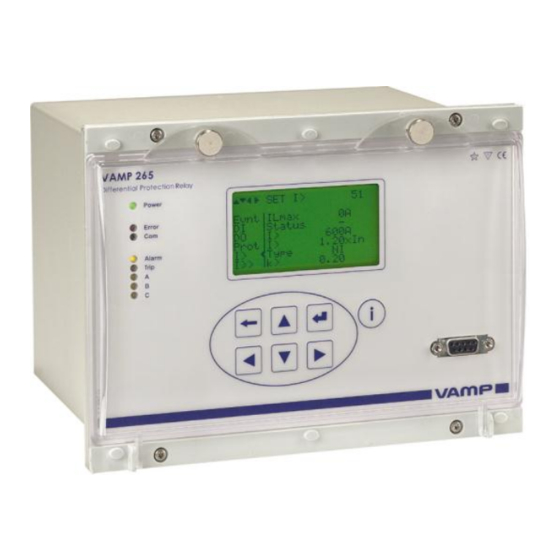
2.1. Relay front panel The figure below shows, as an example, the front panel of the relay VAMP 265 and the location of the user interface elements used for local control. Figure 2.1-1. The front panel of VAMP 265 1. LCD dot matrix display 2. -
Page 7: Display
Figure 2.1.1-2 Sections of the LCD dot matrix display 1. Main menu column 2. The heading of the active menu 3. The cursor of the main menu 4. Possible navigating directions (push buttons) 5. Measured/setting parameter 6. Measured/set value VM265.EN011 VAMP 24h support phone +358 (0)20 753 3264... -
Page 8: Menu Navigation And Pointers
4. Keys for selecting submenus [selecting a digit in a numerical value] (LEFT/RIGHT) 5. Additional information key (INFO) NOTE! The term, which is used for the buttons in this manual, is inside the brackets. VAMP 24h support phone +358 (0)20 753 3264 VM265.EN011... -
Page 9: Operation Indicators
(For more resetting depends on the information about output type of configuration, relay configuration, please connected or latched. see chapter 2.4.5). A- C LED lit Application-related status Configurable indicators. VM265.EN011 VAMP 24h support phone +358 (0)20 753 3264... -
Page 10: Adjusting Display Contrast
The readability of the LCD varies with the brightness and the temperature of the environment. The contrast of the display can be adjusted via the PC user interface, see chapter 3. VAMP 24h support phone +358 (0)20 753 3264 VM265.EN011... -
Page 11: Local Panel Operations
The active main menu selection is indicated with black back- ground color. The possible navigating directions in the menu are shown in the upper-left corner by means of black triangular symbols. Figure 2.2.1-1. Example of scroll indication VM265.EN011 VAMP 24h support phone +358 (0)20 753 3264... - Page 12 The general menu structure is shown in Figure 2.2.1-2. The menu is dependent on the user’s configuration and the options according the order code. For example only the enabled protection stages will appear in the menu. VAMP 24h support phone +358 (0)20 753 3264 VM265.EN011...
- Page 13 50N/51N Io>>>> 4th earth fault stage 50N/51N Prg1 1st programmable stage Prg2 2nd programmable stage Prg3 3rd programmable stage Prg4 4th programmable stage Prg5 5th programmable stage Prg6 6th programmable stage VM265.EN011 VAMP 24h support phone +358 (0)20 753 3264...
-
Page 14: Menu Structure Of Protection Functions
The general structure of all protection function menus is similar although the details do differ from stage to stage. As an example the details of the second overcurrent stage I>> menus are shown below. VAMP 24h support phone +358 (0)20 753 3264 VM265.EN011... - Page 15 “Configurator”. If no front panel button is pressed within five minutes and there is no VAMPSET communication, the force flag will be set to “Off” position. The forcing is explained in chapter 2.3.4. VM265.EN011 VAMP 24h support phone +358 (0)20 753 3264...
- Page 16 "Operator". Operating levels are explained in chapter 2.2.5. t>> 0.60s The total operation delay is set to 600 ms. This value can be edited if the operating level is at least "Operator". VAMP 24h support phone +358 (0)20 753 3264 VM265.EN011...
- Page 17 SetGrp 1 The setting group has been 1. This line can be reached by pressing ENTER and several times the DOWN button. VM265.EN011 VAMP 24h support phone +358 (0)20 753 3264...
-
Page 18: Setting Groups
(the LEFT key is used when the active setting group is 2 and the RIGHT key is used when the active setting group is 1). Figure 2.2.3-2. Example of I> setting submenu VAMP 24h support phone +358 (0)20 753 3264 VM265.EN011... -
Page 19: Fault Logs
(See Figure 2.2.4-2, Log2 = log two). The log two is selected by pressing the RIGHT key once. Figure 2.2.4-2. Example of selected fault log VM265.EN011 VAMP 24h support phone +358 (0)20 753 3264... -
Page 20: Operating Levels
Opening: Default password is 2 Setting state: Push ENTER Closing: The level is automatically closed after 10 minutes idle time. Giving the password 9999 can also close the level. VAMP 24h support phone +358 (0)20 753 3264 VM265.EN011... - Page 21 Get the serial number of the relay (Example: 12345) Send both the numbers to vampsupport@vamp.fi and ask for a password break. A device specific break code is sent back to you. That code will be valid for the next two weeks.
-
Page 22: Operating Measures
2. Select the virtual input object (empty or black square) 3. The dialog opens 4. Select “VIon” to activate the virtual input or select “VIoff” to deactivate the virtual input VAMP 24h support phone +358 (0)20 753 3264 VM265.EN011... -
Page 23: Measured Data
Total harmonic distortion of phase DISTORTION current IL2 [%] THDIL3 I/HARM. Total harmonic distortion of phase DISTORTION current IL3 [%] THDI’L1 I/HARM. Total harmonic distortion of phase DISTORTION current I’L1 [%] VM265.EN011 VAMP 24h support phone +358 (0)20 753 3264... - Page 24 Diagram I/HARMONICS of I’L2 Harmonics of phase current I’L2 [%] (see Figure 2.3.2-1) Diagram I/HARMONICS of I’L3 Harmonics of phase current I’L3 [%] (see Figure 2.3.2-1) Figure 2.3.2-1. Example of harmonics bar display VAMP 24h support phone +358 (0)20 753 3264 VM265.EN011...
-
Page 25: Reading Event Register
It is possible to set the order in which the events are sorted. If the “Order” -parameter is set to “New-Old”, then the first event in the EVENT LIST is the most recent event. VM265.EN011 VAMP 24h support phone +358 (0)20 753 3264... -
Page 26: Forced Control (Force)
10. Repeat the steps 1...4 to exit the Force function. 11. Push the CANCEL key to return to the main menu. NOTE! All the interlockings and blockings are bypassed when the force control is used. VAMP 24h support phone +358 (0)20 753 3264 VM265.EN011... -
Page 27: Configuration And Parameter Setting
ENTER key again. The parameter can now be set. When the parameter change is confirmed with the ENTER key, a [RESTART]- text appears to the top-right corner of the display. This means that auto-resetting is VM265.EN011 VAMP 24h support phone +358 (0)20 753 3264... -
Page 28: Parameter Setting
6. Push the ENTER key to accept a new value. If you want to leave the parameter value unchanged, exit the edit state by pushing the CANCEL key. Figure 2.4.1-1.Changing parameters VAMP 24h support phone +358 (0)20 753 3264 VM265.EN011... -
Page 29: Setting Range Limits
The allowed setting range is shown in the display in the setting mode. To view the range, push the INFO key. Push the CANCEL key to return to the setting mode. Figure 2.4.2-2. Allowed setting ranges show in the display VM265.EN011 VAMP 24h support phone +358 (0)20 753 3264... -
Page 30: Disturbance Recorder Menu Dr
Operation counters (DI COUNTERS) Operation delay (DELAYs for DigIn) The polarity of the input signal (INPUT POLARITY). Either normally open (NO) or normally closed (NC) circuit. Event enabling EVENT MASK1 VAMP 24h support phone +358 (0)20 753 3264 VM265.EN011... -
Page 31: Configuring Digital Outputs Do
The relay includes several protection functions. However, the processor capacity limits the number of protection functions that can be active at the same time. VM265.EN011 VAMP 24h support phone +358 (0)20 753 3264... -
Page 32: Configuration Menu Conf
CT is 5 A or 1A. This increases the measurement accuracy. The rated CT secondary may also be less than the rated input but the measurement accuracy near zero current will decrease. VAMP 24h support phone +358 (0)20 753 3264 VM265.EN011... - Page 33 "User". Offset, i.e. constant error, of the synchronization source (SyOS). Auto adjust interval (AAIntv). Average drift direction (AvDrft): "Lead" or "lag". Average synchronization deviation (FilDev). VM265.EN011 VAMP 24h support phone +358 (0)20 753 3264...
-
Page 34: Protocol Menu Bus
Message counter [Msg#]. This can be used to verify that the device is receiving messages. Communication error counter [Errors] Communication time-out error counter [Tout]. Same information as in the previous menu. VAMP 24h support phone +358 (0)20 753 3264 VM265.EN011... - Page 35 I/O modules connected to the extension port. Only one instance of this protocol is possible. Bit rate [bit/s]. Default is "9600". Parity [Parity]. Default is "Even". For details see the technical description part of the manual. VM265.EN011 VAMP 24h support phone +358 (0)20 753 3264...
- Page 36 “-“, either Profibus protocol has not been selected or the device has not restarted after protocol change or there is a communication problem between the main CPU and the Profibus ASIC. VAMP 24h support phone +358 (0)20 753 3264 VM265.EN011...
-
Page 37: Single Line Diagram Editing
Furthermore, the interlocking between objects can be configured in the same blocking matrix of the VAMPSET software. For more information, please refer to the VAMPSET manual (VMV.EN0xx). VM265.EN011 VAMP 24h support phone +358 (0)20 753 3264... -
Page 38: Vampset Pc Software
The VAMPSET program can also use TCP/IP LAN connection. Optional hardware is required. There is a free of charge PC program called VAMPSET available for configuration and setting of VAMP relays. Please download the latest VAMPSET.exe from our web page www.vamp.fi. For more information about the VAMPSET software, please refer to the user’s manual with the code... - Page 39 ..................122 4.7. Primary, secondary and per unit scaling....123 4.7.1. Current scaling ............123 5. Control functions ..............126 5.1. Output relays ..............126 5.2. Digital inputs ..............127 VM265.EN011 VAMP 24h support phone +358 (0)20 753 3264...
- Page 40 7.9. Trip Circuit Supervision ..........170 7.9.1. Trip circuit supervision with one digital input ..170 7.9.2. Trip circuit supervision with DI19 and DI20 ..178 8. Connections ............... 182 8.1. Rear panel view ............182 VAMP 24h support phone +358 (0)20 753 3264 VM265.EN011...
- Page 41 9.4.1. Disturbance recorder (DR) ........212 10. Abbreviations and symbols ..........213 11. Construction ............... 214 12. Order information ............... 215 13. Revision history ..............216 14. Reference information ............218 VM265.EN011 VAMP 24h support phone +358 (0)20 753 3264...
-
Page 42: Introduction
The generator, transformer and motor differential protection relay VAMP 265 can be used for selective differential overcurrent, short-circuit protection of generators, trans- formers and motors in solidly or impedance earthed power systems. -
Page 43: Main Features
Built-in, self-regulating ac/dc converter for auxiliary power supply from any source within the range from 40 to 265 V dc or ac. The alternative power supply is for 18 to 36 V dc. Built-in disturbance recorder for evaluating all the analogue and digital signals. -
Page 44: Principles Of Numerical Protection Techniques
Figure 1.2-3 shows a block diagram of a basic overcurrent or overvoltage function with definite and inverse operation time. VAMP 24h support phone +358 (0)20 753 3264 VM265.EN011... - Page 45 Technical description 1 Introduction 1.2 Principles of numerical protection techniques Figure 1.2-1. Principle block diagram of the VAMP 265 hardware. Figure 1.2-2. Block diagram of signal processing and protection software. Figure 1.2-3. Block diagram of a basic protection function. VM265.EN011...
-
Page 46: Protection Functions
Thermal overload protection >, >>, 50N/51N Earth fault protection >>>, >>>> 50BF CBFP Circuit-breaker failure protection Prg1...8 Programmable stages 50ARC ArcI>, ArcI‟> Optional arc fault protection 50NARC ArcI >, ArcI > VAMP 24h support phone +358 (0)20 753 3264 VM265.EN011... -
Page 47: General Features Of Protection Stages
After testing the force flag will automatically reset 5-minute after the last local panel push button activity. The force flag also enables forcing of the output relays and forcing the optional mA outputs. VM265.EN011 VAMP 24h support phone +358 (0)20 753 3264... - Page 48 This parameter is important when grading the operation time delay settings between relays. Figure 2.3-1. Definition for retardation time. If the delay setting would be slightly shorter, an unselective trip might occur (the dash line pulse). VAMP 24h support phone +358 (0)20 753 3264 VM265.EN011...
- Page 49 (the dashed 40 ms pulse in the figure). In VAMP relays the retardation time is less than 50 Reset time (release time) Figure 2.3-2 shows an example of reset time i.e. release delay, when the relay is clearing an overcurrent fault.
- Page 50 (dead band) acts according this figure. Figure 2.3-4. Behaviour of a less than comparator. For example in under- voltage and under frequency stages the hysteresis (dead band) acts according this figure. VAMP 24h support phone +358 (0)20 753 3264 VM265.EN011...
-
Page 51: Differential Overcurrent Protection Δi> (87)
(IL side), see Figure 2.4-2. Figure 2.4-2 Winding currents in connection group Dy11. Equation 1: Winding current calculation in delta side, Dy11 connection VM265.EN011 VAMP 24h support phone +358 (0)20 753 3264... - Page 52 Yy0, see Table 2.4-2. Also the settings of Un and U‟n are set to be the same, e.g. generator nominal voltage. VAMP 24h support phone +358 (0)20 753 3264 VM265.EN011...
- Page 53 YNd7 Yd11 Yd11 YNd11 Yd11 Dyn1 Dyn5 Dyn7 Dy11 Dy11 Dyn11 Dy11 Table 2.4-2 Zero current compensation in generator applications Genarator only Relay setting ConnGrp Io cmps I'o cmps None earthing VM265.EN011 VAMP 24h support phone +358 (0)20 753 3264...
- Page 54 The stage also includes second harmonics blocking. The second harmonic is calculated from winding currents. Harmonic ratio 100 x I [%]. f2_Winding f1_Winding Fast differential overcurrent stage I>> does not include slope characteristics and second harmonics blocking. VAMP 24h support phone +358 (0)20 753 3264 VM265.EN011...
- Page 55 = fault between L2 and L3 1-2-3 Fault type/three-phase fault Flt Max. value of fault differential current as compared to I Load 1 s mean value of pre-fault phase currents IL1…IL3 VM265.EN011 VAMP 24h support phone +358 (0)20 753 3264...
-
Page 56: Overcurrent Protection I> (50/51)
See chapter 2.13 for more information. Setting groups There are two settings groups available for each stage. Switching between setting groups can be controlled by digital inputs, virtual inputs (mimic display, communication, logic) and manually. VAMP 24h support phone +358 (0)20 753 3264 VM265.EN011... - Page 57 This flag is automatically reset 5 minutes after the last front panel push button pressing. ILmax The supervised value. Max. of IL1, IL2 and IL3 VM265.EN011 VAMP 24h support phone +358 (0)20 753 3264...
- Page 58 See chapter 2.13. For details of setting ranges see chapter 9.3. Set = An editable parameter (password needed) C = Can be cleared to zero F = Editable when force flag is on VAMP 24h support phone +358 (0)20 753 3264 VM265.EN011...
- Page 59 Recorded values of the latest eight faults There are detailed information available of the eight latest faults: Time stamp, fault type, fault current, load current before the fault, elapsed delay and setting group. VM265.EN011 VAMP 24h support phone +358 (0)20 753 3264...
-
Page 60: Current Unbalance Protection I > (46)
The inverse delay is based on the following equation. Equation 2.6-1 , where Operation time Delay multiplier Measured and calculated negative sequence phase current of fundamental frequency. Rated current VAMP 24h support phone +358 (0)20 753 3264 VM265.EN011... - Page 61 (mimic display, communication, logic) and manually. Figure 2.6-1. Inverse operation delay of current unbalance stage I >. The longest delay is limited to 1000 seconds (=16min 40s). VM265.EN011 VAMP 24h support phone +358 (0)20 753 3264...
- Page 62 Time stamp of the recording, date hh:mm:ss.ms Time stamp, time of day Maximum unbalance current EDly Elapsed time of the operating time setting. 100% = trip SetGrp Active setting group during the fault VAMP 24h support phone +358 (0)20 753 3264 VM265.EN011...
-
Page 63: Earth Fault Protection I > (50N/51N)
Figure 2.7-2 shows a functional block diagram of the >>, I >>> and I >>>> earth fault stages with definite time operation delay. VM265.EN011 VAMP 24h support phone +358 (0)20 753 3264... - Page 64 (DT) or inverse time operation characteristic (IDMT). The other stages have definite time operation characteristic. By using the definite delay type and setting the delay to its minimum, an instantaneous (ANSI 50N) operation is obtained. VAMP 24h support phone +358 (0)20 753 3264 VM265.EN011...
- Page 65 LEDx Virtual output Force Force flag for status forcing for test purposes. This is a common flag for all stages and output relays, too. Automatically reset by a 5- minute timeout. VM265.EN011 VAMP 24h support phone +358 (0)20 753 3264...
- Page 66 See chapter 2.13. For details of setting ranges see chapter 9.3. Set = An editable parameter (password needed) C = Can be cleared to zero F = Editable when force flag is on VAMP 24h support phone +358 (0)20 753 3264 VM265.EN011...
- Page 67 F = Editable when force flag is on Recorded values of the latest eight faults There is detailed information available of the eight latest earth faults: Time stamp, fault current, elapsed delay and setting group. VM265.EN011 VAMP 24h support phone +358 (0)20 753 3264...
-
Page 68: Thermal Overload Protection T> (49)
rise is 120% ). This parameter is the memory of the algorithm and corresponds to the actual temperature rise. Overload factor (Maximum continuous current), i.e. service factor. (Setting value) VAMP 24h support phone +358 (0)20 753 3264 VM265.EN011... - Page 69 = 1. This is true when I is 1.0 max40 Samb is “n/a” (no ambient temperature sensor) TAMB is +40 °C. Figure 2.8-1 Ambient temperature correction of the overload stage T>. VM265.EN011 VAMP 24h support phone +358 (0)20 753 3264...
- Page 70 The thermal overload stage is provided with a separately settable alarm function. When the alarm limit is reached the stage activates its start signal. Figure 2.8-1. Example of the thermal model behaviour. VAMP 24h support phone +358 (0)20 753 3264 VM265.EN011...
- Page 71 External Analogue input 1...16 For details of setting ranges see chapter 9.3. Set = An editable parameter (password needed) C = Can be cleared to zero F = Editable when force flag is on VM265.EN011 VAMP 24h support phone +358 (0)20 753 3264...
-
Page 72: Second Harmonic O/C Stage I >(51F2)
Definite operating time S_On Enabled; Enabled Start on event Disabled S_Off Enabled; Enabled Start off event Disabled T_On Enabled; Enabled Trip on event Disabled T_Off Enabled; Enabled Trip off event Disabled VAMP 24h support phone +358 (0)20 753 3264 VM265.EN011... -
Page 73: Circuit-Breaker Failure Protection Cbfp (50Bf)
The CBFP stage is supervising all the protection stages using the same selected trip relay, since it supervises the control signal of this relay. See chapter 5.4 for details about the output matrix and the trip relays. VM265.EN011 VAMP 24h support phone +358 (0)20 753 3264... - Page 74 CBFP (50BF) Parameter Value Unit Description yyyy-mm-dd Time stamp of the recording, date hh:mm:ss.ms Time stamp, time of day EDly Elapsed time of the operating time setting. 100% = trip VAMP 24h support phone +358 (0)20 753 3264 VM265.EN011...
-
Page 75: Arc Fault Protection (50Arc/50Narc) (Optional)
BO, indicators etc. offered by the output matrix (See chapter 5.4). BI is a dry input for 48 Vdc signal from binary outputs of other VAMP relays or dedicated arc protection devices by VAMP. - Page 76 Selection of the BO connected signal(s) is done with the output matrix (See chapter 5.4). BO is an internally wetted 48 Vdc signal for BI of other VAMP relays or dedicated arc protection devices by VAMP.
- Page 77 Sensor 1 at terminals X6:4-5 Sensor 2 at terminals X6:6-7 S1/S2 Terminals X6:1-3 S1/BI S2/BI S1/S2/BI For details of setting ranges see chapter 9.3. Set = An editable parameter (password needed) VM265.EN011 VAMP 24h support phone +358 (0)20 753 3264...
- Page 78 Time stamp, time of day Type Fault type value. Only for ArcI> stage. Fault value Load Pre fault current. Only for ArcI> stage. EDly Elapsed time of the operating time setting. 100% = trip VAMP 24h support phone +358 (0)20 753 3264 VM265.EN011...
-
Page 79: Programmable Stages (99)
Io, Io2, Iocalc, I‟oCalc, I1, I2, I2/I1, I2/In, I‟1, I‟2, I‟2/I‟1, I‟2/In, dIL1, dIL2, dIL3 THDIL1, THDIL2, THDIL3 Eight independent stages The relay has eight independent programmable stages. Each programmable stage can be enabled or disabled to fit the intended application. VM265.EN011 VAMP 24h support phone +358 (0)20 753 3264... - Page 80 Dead band setting NoCmp Minimum value to start under comparison. (Mode='<') Set = An editable parameter (password needed) C = Can be cleared to zero F = Editable when force flag is on VAMP 24h support phone +358 (0)20 753 3264 VM265.EN011...
-
Page 81: Inverse Time Operation
This mode is activated by setting delay type to „Parameters‟, and then editing the delay function parameters A ... E. See chapter 2.13.2. VM265.EN011 VAMP 24h support phone +358 (0)20 753 3264... - Page 82 (earth fault stages using I input or I input). The I and I and I depend on the order code (See chapter 12). The table below gives the limit values in secondary amperes. VAMP 24h support phone +358 (0)20 753 3264 VM265.EN011...
- Page 83 Secondary scaled I is now 3.85 A GNsec For 5 A CT secondaries and 1 A residual current inputs VAMP relay VAMP 265-5D7AAA is used. It has 5 A phase current inputs and 1 A residual inputs. For overcurrent stage I> the table below gives 12.5 A. Thus the maximum setting for I>...
-
Page 84: Standard Inverse Delays Iec, Ieee, Ieee2, Ri
Equation 2.13.1-1. Actually this equation can only be used to draw graphs or when the measured value I is constant during the fault. A modified version is implemented in the relay for real time usage. VAMP 24h support phone +358 (0)20 753 3264 VM265.EN011... -
Page 85: Ni1 Normal Inverse
Long time inverse Example for Delay type "Normal inverse (NI) ": 0.50 4 pu (constant current) 2 pu pickup 0.14 0.02 VM265.EN011 VAMP 24h support phone +358 (0)20 753 3264... - Page 86 Figure 2.13.1-1 . Figure 2.13.1-1 IEC normal inverse Figure 2.13.1-2 IEC extremely inverse delay. delay. Figure 2.13.1-3 IEC very inverse Figure 2.13.1-4 IEC long time inverse delay. delay. VAMP 24h support phone +358 (0)20 753 3264 VM265.EN011...
-
Page 87: Ltvi Long Time Very Inverse
Table 2.12.1-3. The IEEE standard defines inverse delay for both trip and release operations. However, in the VAMP relay only the trip time is inverse according the standard but the release time is constant. The operation delay depends on the measured value and other parameters according Equation 2.13.1-1. - Page 88 The operation time in this example will be 1.9 seconds. The same result can be read from Figure 2.13.1-8. Figure 2.13.1-5 ANSI/IEEE long Figure 2.13.1-6 ANSI/IEEE long time inverse delay time very inverse delay VAMP 24h support phone +358 (0)20 753 3264 VM265.EN011...
-
Page 89: Mi Moderately Inverse
2.13 Inverse time operation Figure 2.13.1-7 ANSI/IEEE long Figure 2.13.1-8 ANSI/IEEE time extremely inverse delay moderately inverse delay Figure 2.13.1-9 ANSI/IEEE short Figure 2.13.1-10 ANSI/IEEE short time inverse delay time extremely inverse delay VM265.EN011 VAMP 24h support phone +358 (0)20 753 3264... - Page 90 There are four different delay types according Table 2.13.1-1. The old electromechanical induction disc relays have inverse delay for both trip and release operations. However, in VAMP device only the trip time is inverse the release time being constant.
- Page 91 The operation time in this example will be 0.38 seconds. The same result can be read from Figure 2.13.1-11. Figure 2.13.1-11 IEEE2 moderately Figure 2.13.1-12 IEEE2 normal inverse delay inverse delay VM265.EN011 VAMP 24h support phone +358 (0)20 753 3264...
- Page 92 pickup Equation 2.13.1-4 RXIDG 5 RXIDG pickup = Operation delay in seconds = User‟s multiplier = Measured value = User‟s pick up setting pickup VAMP 24h support phone +358 (0)20 753 3264 VM265.EN011...
- Page 93 The operation time in this example will be 3.9 seconds. The same result can be read from Figure 2.13.1-16. Figure 2.13.1-15 Inverse delay of Figure 2.13.1-16 Inverse delay of type RI. type RXIDG. VM265.EN011 VAMP 24h support phone +358 (0)20 753 3264...
-
Page 94: Free Parametrisation Using Iec, Ieee And Ieee2 Equations
The minimum definite time delay start latest, when the measured value is twenty times the setting. However, there are limitations at high setting values due to the measurement range. See chapter 2.13 for more details. VAMP 24h support phone +358 (0)20 753 3264 VM265.EN011... -
Page 95: Programmable Inverse Time Curves
The minimum definite time delay start latest, when the measured value is twenty times the setting. However, there are limitations at high setting values due to the measurement range. See chapter 2.13 for more details. VM265.EN011 VAMP 24h support phone +358 (0)20 753 3264... -
Page 96: Supporting Functions
Modification can be done in “Local panel conf” – menu. Alarm screen (popup screen) can also be enabled in this same menu when Vampset –setting tool is used. The oldest one VAMP 24h support phone +358 (0)20 753 3264 VM265.EN011... - Page 97 FORMAT OF EVENTS ON THE LOCAL DISPLAY Code: CHENN CH = event channel, NN=event code Event description Event channel and code in plain text yyyy-mm-dd Date (for available date formats see chapter 3.5) hh:mm:ss.nnn Time VM265.EN011 VAMP 24h support phone +358 (0)20 753 3264...
-
Page 98: Disturbance Recorder
(includes all the inputs). Also the digital outputs reserve one channel (includes all the outputs). If digital inputs and outputs are recorded, there will be still 10 channels left for analogue waveforms. VAMP 24h support phone +358 (0)20 753 3264 VM265.EN011... - Page 99 IL1 RMS for average sampling IL2RMS IL2 RMS for average sampling IL3RMS IL3 RMS for average sampling ILmin I‟Lmin ILmax I‟Lmax ΔIL1,ΔIL2,ΔIL3 IL1w,IL2w,IL3w I‟L1w,I‟L2w,I‟L3w VM265.EN011 VAMP 24h support phone +358 (0)20 753 3264...
- Page 100 ReadyRec n = Available recordings m = maximum number of recordings The value of 'm' depends on sample rate, number and type of the selected channels and the configured recording length. VAMP 24h support phone +358 (0)20 753 3264 VM265.EN011...
- Page 101 Set = An editable parameter (password needed) *) This is the fundamental frequency rms value of one cycle updated every 10 ms. **) This is the fundamental frequency rms value of one cycle updated every 20 ms. VM265.EN011 VAMP 24h support phone +358 (0)20 753 3264...
- Page 102 Technical description Running virtual comtrade files with VAMP relays Virtual comtrade files can be run with VAMP relays with the v.10.74 software or a later version. Relay behaviour can be analysed by playing the recorder data over and over again in the relay memory.
-
Page 103: Current Transformer Supervision
Display Imax>, Setting values as primary values Imin< Recorded Date Date of CT supervision alarm values Time Time of CT supervision alarm Imax Maximum phase current Imin Minimum phase current VM265.EN011 VAMP 24h support phone +358 (0)20 753 3264... -
Page 104: Circuit Breaker Condition Monitoring
The points 4...8 are not needed for the CB in Figure 3.4-1. Thus they are set to 100 kA and one operation in the table to be discarded by the algorithm. Figure 3.4-1. An example of a circuit breaker wearing characteristic graph. VAMP 24h support phone +358 (0)20 753 3264 VM265.EN011... - Page 105 The operations left can be read from the counters "Al1Ln" (Alarm 1) and "Al2Ln" (Alarm2). There are three values for both alarms, one for each phase. The smallest of three is supervised by the two alarm functions. VM265.EN011 VAMP 24h support phone +358 (0)20 753 3264...
- Page 106 The current 6 kA lies between points 2 and 3 in the table. That gives value for the index k. Using = 10000 = 80 = 31 kA = 1.25 kA and the Equation 3.4-2 and Equation 3.4-3 , the relay calculates VAMP 24h support phone +358 (0)20 753 3264 VM265.EN011...
- Page 107 Thus Alarm2 counters for phases L1 and L2 are decremented by 3. In phase L1 the currents is less than the alarm limit current 6 kA. For such currents the decrement is one. VM265.EN011 VAMP 24h support phone +358 (0)20 753 3264...
- Page 108 'Alarm2 on' event enabling Al2Off 'Alarm2 off' event enabling Clear Clearing of cycle counters Clear Set = An editable parameter (password needed) The breaker curve table is edited with VAMPSET. VAMP 24h support phone +358 (0)20 753 3264 VM265.EN011...
-
Page 109: System Clock And Synchronization
1000, if some other period than one week has been used. For example if the drift has been 37 seconds in 14 days, the relative drift is 37*1000/(14*24*3600) = 0.0306 ms/s. VM265.EN011 VAMP 24h support phone +358 (0)20 753 3264... - Page 110 NOTE! When the internal time is roughly correct – deviation is less than four seconds – any synchronizing or auto-adjust will never turn the clock backwards. Instead, in case the clock is leading, it is softly slowed down to maintain causality. VAMP 24h support phone +358 (0)20 753 3264 VM265.EN011...
- Page 111 AAIntv 10000 Adapted auto adjust interval for 1 ms correction AvDrft Lead Adapted average clock drift sign FilDev 125 Filtered synchronisation deviation Set = An editable parameter (password needed). VM265.EN011 VAMP 24h support phone +358 (0)20 753 3264...
-
Page 112: Running Hour Counter
Date and time of the last activation Stopped at Date and time of the last inactivation Set = An editable parameter (password needed). (Set) = An informative value which can be edited as well. VAMP 24h support phone +358 (0)20 753 3264 VM265.EN011... -
Page 113: Timers
3.7 Timers 3.7. Timers The VAMP protection platform includes four settable timers that can be used together with the user's programmable logic or to control setting groups and other applications that require actions based on calendar time. Each timer has its own settings. - Page 114 The timer switches on and off every day except Saturdays and Sundays MTWTFS The timer switches on and off every day except Sundays. SatSun The timer switches on and off every Saturday and Sunday. VAMP 24h support phone +358 (0)20 753 3264 VM265.EN011...
-
Page 115: Combined Overcurrent Status
Several events are enabled Several events of an increasing fault is disabled ClrDly 0 ... 65535 Duration for active alarm status AlrL1, Alr2, AlrL3 and Ocs VM265.EN011 VAMP 24h support phone +358 (0)20 753 3264... - Page 116 Not used with Spabus, because Spabus masters usually don't like to have unpaired On/Off events. **) Used with SPA-bus protocol, because most SPA-bus masters do need an off-event for each corresponding on-event. VAMP 24h support phone +358 (0)20 753 3264 VM265.EN011...
-
Page 117: Self-Supervision
(IF) output relay functions on a working current principle. This means that the IF relay is energized when the auxiliary supply is on and no internal fault is detected. VM265.EN011 VAMP 24h support phone +358 (0)20 753 3264... -
Page 118: Measurement Functions
Figure 4-1 Example of various current values of a transformer inrush current. VAMP 24h support phone +358 (0)20 753 3264 VM265.EN011... -
Page 119: Measurement Accuracy
5A or 1A. This must be specified when ordering the relay. Frequency Measuring range 16 Hz – 75 Hz Inaccuracy 10 mHz In VAMP 265 frequency is measured from current signals. THD and harmonics Inaccuracy I 0.1 PU 2 % units Update rate Once a second The specified frequency range is 45 Hz –... -
Page 120: Harmonics And Total Harmonic Distortion (Thd)
13.0 %. 4.3. RMS values RMS currents Relay calculates the RMS value of each phase current. The minimum and the maximum of RMS values are recorded and stored. VAMP 24h support phone +358 (0)20 753 3264 VM265.EN011... -
Page 121: Demand Values
Demand values of phase currents, rms values (rms value) The clearing parameter "ClrMax" is common for all these values. Parameters Parameter Value Description ClrMax Reset all minimum and maximum values Clear VM265.EN011 VAMP 24h support phone +358 (0)20 753 3264... -
Page 122: Maximum Values Of The Last 31 Days And Twelve Months
Collect min & max of demand values (see chapter 4.4) ResetDays Reset the 31 day registers ResetMon Reset the 12 month registers *) This is the fundamental frequency rms value of one cycle updated every 20 ms. VAMP 24h support phone +358 (0)20 753 3264 VM265.EN011... -
Page 123: Primary, Secondary And Per Unit Scaling
= 100 %, where is the rated current of the transformer. The rated current for high voltage side (HV) and low voltages side (LV) are calculated by the device itself using Equation 4.7.1-1. VM265.EN011 VAMP 24h support phone +358 (0)20 753 3264... - Page 124 Example 2: Secondary to per unit for ArcI>. CT = 750/5 Current injected to the relay's inputs is 7 A. Per unit current is = 7/5 = 1.4 pu = 140 % VAMP 24h support phone +358 (0)20 753 3264 VM265.EN011...
- Page 125 Input is I 0Calc CT = 750/5 The relay setting is 0.1 pu = 10 %. If I = 0, then secondary current to I = 0.1x5 = 0.5 A VM265.EN011 VAMP 24h support phone +358 (0)20 753 3264...
-
Page 126: Control Functions
An output relay can be configured as latched or non- latched. See output matrix for more details. NOTE! If the VAMP device has the mA option, it is equipped with only three alarm relays from A1 to A3. The difference between trip contacts and alarm contacts is the DC breaking capacity. -
Page 127: Digital Inputs
No pop-up display Alarm pop-up display is activated at active DI edge On event Active edge event enabled Active edge event disabled Off event Inactive edge event enabled Inactive edge event disabled VM265.EN011 VAMP 24h support phone +358 (0)20 753 3264... - Page 128 Summary of digital inputs: Terminal Operating voltage Availability X3:1 supply for DI1…6 X3:2 X3:3 X3:4 VAMP 265 Internal 48V X3:5 X3:6 X3:7 External 18…265 V X6:1…2 ARC card with 2 DIs 50…250 V VAMP 24h support phone +358 (0)20 753 3264 VM265.EN011...
-
Page 129: Virtual Inputs And Outputs
Virtual outputs are shown in the output matrix and the block matrix. Virtual outputs can be used with the user's programmable logic and to change the active setting group etc. VM265.EN011 VAMP 24h support phone +358 (0)20 753 3264... -
Page 130: Output Matrix
The selection of the input is done with the VAMPSET software under the menu "Release output matrix latches". Under the same menu, the "Release latches" parameter can be used for resetting. Figure 5.4-1 Output matrix. VAMP 24h support phone +358 (0)20 753 3264 VM265.EN011... -
Page 131: Blocking Matrix
In the block matrix Figure 5.5-1 an active blocking is indicated with a black dot (•) in the crossing point of a blocking signal and the signal to be blocked. Figure 5.5-1 Blocking matrix and output matrix VM265.EN011 VAMP 24h support phone +358 (0)20 753 3264... -
Page 132: Controllable Objects
“Object failure” matrix signal is set. Also undefined-event is generated. “Completion timeout” is only used for the ready indication. If “DI for „obj ready‟” is not set, completion timeout has no meaning. VAMP 24h support phone +358 (0)20 753 3264 VM265.EN011... - Page 133 If the device is in local control state, the remote control inputs are ignored and vice versa. Object is controlled when a rising edge is detected from the selected input. Length of digital input pulse should be at least 60 ms. VM265.EN011 VAMP 24h support phone +358 (0)20 753 3264...
-
Page 134: Local/Remote Selection
Maximum number of outputs is 20. Maximum number of input gates is 31. An input gate can include any number of inputs. For detailed information, please refer to the VAMPSET manual (VMV.EN0xx). VAMP 24h support phone +358 (0)20 753 3264 VM265.EN011... -
Page 135: Communication
By default the remote port has a TTL interface. It can only be used together with external converters or converting cables. Inbuilt options for RS-485, fibre optic (plastic/plastic, plastic/glass, glass/plastic or glass/glass), Profibus and Ethernet are available. VM265.EN011 VAMP 24h support phone +358 (0)20 753 3264... -
Page 136: Local Port X4
The communication parameter display on the local display will show the active parameter values for the local port. Physical interface The physical interface of this port is RS-232. VAMP 24h support phone +358 (0)20 753 3264 VM265.EN011... - Page 137 Clr = Clearing to zero is possible 1) The communication parameters are set in the protocol specific menus. For the local port command line interface the parameters are set in configuration menu. VM265.EN011 VAMP 24h support phone +358 (0)20 753 3264...
-
Page 138: Remote Port X5
Clr = Clearing to zero is possible 1) The communication parameters are set in the protocol specific menus. For the local port command line interface the parameters are set in configuration menu. VAMP 24h support phone +358 (0)20 753 3264 VM265.EN011... -
Page 139: Extension Port X4
Clr = Clearing to zero is possible 1) The communication parameters are set in the protocol specific menus. For the local port command line interface the parameters are set in configuration menu. VM265.EN011 VAMP 24h support phone +358 (0)20 753 3264... -
Page 140: Ethernet Port
0.0.0.0 = no SNTP VS Port IP port for Vampset KeepAlive TCP keepalive interval nnnnnnnnnnnn MAC address Msg# Message counter Errors Error counter Tout Timeout counter Set = An editable parameter (password needed) VAMP 24h support phone +358 (0)20 753 3264 VM265.EN011... -
Page 141: Communication Protocols
Settings (SPA-bus and embedded SPA-bus only) 6.2.1. PC communication PC communication is using a VAMP specified command line interface. The VAMPSET program can communicate using the local RS-232 port or using ethernet interface. It is also possible to select SPA-bus protocol for the local port and configure the VAMPSET to embed the command line interface inside SPA- bus messages. -
Page 142: Profibus Dp
Device profile "Request mode" Using the request mode it is possible to read all the available data from the VAMP device and still use only a very short buffer for Profibus data transfer. The drawback is the slower overall speed of the data transfer and the need of increased data processing at the Profibus master as every data item must be separately requested by the master. - Page 143 4) If the value is "", Profibus protocol has not been selected or the device has not restarted after protocol change or there is a communication problem between the main CPU and the Profibus ASIC. VM265.EN011 VAMP 24h support phone +358 (0)20 753 3264...
-
Page 144: Spa-Bus
9600 (default) 19200 Emode Event numbering style. (Set) Channel Use this for new installations. (Limit60) (The other modes are for compatibility with old (NoLimit) systems.) Set = An editable parameter (password needed) VAMP 24h support phone +358 (0)20 753 3264 VM265.EN011... -
Page 145: Iec 60870-5-103
= 90. "Private range" function types are used for such data items, which are not defined by the standard (e.g. the status of the digital inputs and the control of the objects). VM265.EN011 VAMP 24h support phone +358 (0)20 753 3264... - Page 146 Technical description The function type and information number used in private range messages is configurable. This enables flexible interfacing to different master systems. For more information on IEC 60870-5-103 in Vamp devices refer to the “IEC103 Interoperability List” document. Parameters Parameter...
-
Page 147: Dnp 3.0
Application layer confirmation mode EvOnly (default) DBISup Double-bit input support No (default) SyncMode 0 65535 Clock synchronization request interval. 0 = only at boot Set = An editable parameter (password needed) VM265.EN011 VAMP 24h support phone +358 (0)20 753 3264... -
Page 148: Iec 60870-5-101
The IEC 60870-5-101 standard is derived from the IEC 60870-5 protocol standard definition. In Vamp devices, IEC 60870-5-101 communication protocol is available via menu selection. The Vamp unit works as a controlled outstation (slave) unit in unbalanced mode. Supported application functions include process data... -
Page 149: External I/O (Modbus Rtu Master)
Additional information can be obtained from the separate documents “IEC 61850 conformance statement.pdf”, “IEC 61850 Protocol data.pdf” and “Configuration of IEC 61850 interface.pdf” on our website. VM265.EN011 VAMP 24h support phone +358 (0)20 753 3264... - Page 150 T Selector 0 – 64000 Transport selector IED Name String Identifcation of the device. Each device must have unique name. Delete command Send command to clear dynamic all dynamic datasets datasets VAMP 24h support phone +358 (0)20 753 3264 VM265.EN011...
-
Page 151: Ethernet/Ip
/ response), Class 3 connection (cyclic request / response) and Class 1 connection (cyclic IO messages containing assemblies‟ data) EtherNet/IP implementation on VAMP relay serves as a server and is not capable of initiating communication VM265.EN011 VAMP 24h support phone +358 (0)20 753 3264... - Page 152 Header in an outgoing IO messages Header (Producing) Consuming 1-1278 Instance number of consuming Instance assembly Include On/Off Expect presence or absence of Run/Idle Run/Idle Header in an incoming Header IO messages (Consuming) VAMP 24h support phone +358 (0)20 753 3264 VM265.EN011...
-
Page 153: Applications
CTs and wiring by limiting the voltage V during heavy inside faults. The resistance of the secondary loop connecting the CTs together should be as low as possible. VM265.EN011 VAMP 24h support phone +358 (0)20 753 3264... -
Page 154: Restricted Earth Fault Protection For A Transformer With Neutral Connection
CTs and the neutral CT cancel each other and in inside fault the two residual secondary currents are summed up and forced to flow through the I input of the relay and the voltage limiting VDR. VAMP 24h support phone +358 (0)20 753 3264 VM265.EN011... -
Page 155: Ct Requirements
+75 °C. Knee point voltage (V ) is the secondary voltage at which a 50 % increase of primary current is needed to increase the secondary voltage by 10 %. VM265.EN011 VAMP 24h support phone +358 (0)20 753 3264... -
Page 156: Calculating The Stabilizing Resistance R
Selecting a low value helps to achieve more sensitivity and helps to avoid the usage of a voltage limiting VDR. An unselective earth fault pick-up/trip is not always a problem if a fast overcurrent stage will clear the fault anyway. VAMP 24h support phone +358 (0)20 753 3264 VM265.EN011... -
Page 157: Voltage Limitation
The differential scheme will multiply the fault current by two thus increasing the sensitivity from the actual setting. The quiescent current of the possible VDR will decrease the sensitivity from the actual setting value. VM265.EN011 VAMP 24h support phone +358 (0)20 753 3264... -
Page 158: Example
A zinc oxide varistor (i.e. VDR, METROSIL) of 1 kV will limit the voltage. Using a 400 J model allows two 20 VA CTs feeding ten times their nominal power during one second before the energy capacity of the varistor is exceeded. VAMP 24h support phone +358 (0)20 753 3264 VM265.EN011... -
Page 159: Current Transformer Selection
Equation 7.4.1-1 = Cycle time = Rated transformation ratio I NPrimary Nsecondary = Instantaneous secondary current = Instantaneous primary current = Rms value of primary current VM265.EN011 VAMP 24h support phone +358 (0)20 753 3264... - Page 160 The IEC formula includes an RMS value of the current. That is why the composite error defined by IEC 60044-1 is not ideal for VAMP relays. However the difference is not big enough to prevent rough estimation.
- Page 161 CT if the load is much less than the nominal. A 10 VA 5P10 CT with 25% load gives actual ALF values from 15..30 when the winding resistance varies from 0.5 to 0.05 . VM265.EN011 VAMP 24h support phone +358 (0)20 753 3264...
-
Page 162: Ct Requirement For Protection
, should be avoided in this configuration because a set of three CTs are not exactly similar and will produce some secondary residual current even though there is no residual current in the primary side. VAMP 24h support phone +358 (0)20 753 3264 VM265.EN011... - Page 163 Nominal secondary current of the CT NCTsec By solving S and substituting k according Equation 7.4.2-2 , we get Equation 7.4.2-3 NTra VM265.EN011 VAMP 24h support phone +358 (0)20 753 3264...
- Page 164 (Transformer differential, .) Differential current setting of the non-stabilized stage I>>: = 9 x I = 0.008 Typical burden of a VAMP relay current input. = 0.138 Wiring impedance of high voltage side. (2x16 m, 4 mm = 0.086 Wiring impedance of low voltage side.
-
Page 165: Protection Of A Dyn11 Transformer
7 Applications 7.5 Protection of a Dyn11 transformer 7.5. Protection of a Dyn11 transformer Figure 7.5-1 Differential protection of a Dyn11 transformer using VAMP 265. Primary and secondary current transformers are connected according to subtractive polarity. Settings: ConnGrp Dy11 IoCmps I‟oCmps... - Page 166 7.5 Protection of a Dyn11 7 Applications Technical description transformer Figure 7.5-2 Differential protection of a Dyn11 transformer using VAMP 265. Primary and secondary current transformers are connected according to additive polarity. Settings: ConnGrp Dy11 IoCmps I‟oCmps High side voltage U‟n...
-
Page 167: Protection Of A Ynd11 Transformer
Technical description 7 Applications 7.6 Protection of a YNd11 transformer 7.6. Protection of a YNd11 transformer Figure 7.6-1 Differential protection of a YNd11 transformer using VAMP 265. Settings: ConnGrp Yd11 IoCmps I‟oCmps High side voltage U‟n Low side voltage VM265.EN011... -
Page 168: Protection Of Generator And Block Transformer
Protection of generator and block transformer Figure 7.7-1 Differential protection of a YNd11 transformer and generator using VAMP 265. Settings: ConnGrp Yd11 IoCmps I‟oCmps High side voltage U‟n Low side voltage VAMP 24h support phone +358 (0)20 753 3264 VM265.EN011... -
Page 169: Application Example Of Differential Protection Using
Technical description 7 Applications 7.8 Application example of differential protection using VAMP 7.8. Application example of differential protection using VAMP 265 Figure 7.8-1 Differential protection of a generator using VAMP 265. Settings: ConnGrp IoCmps I‟oCmps Generator nominal voltage U‟n Generator nominal voltage VM265.EN011... -
Page 170: Trip Circuit Supervision
The digital inputs of the device can be used for trip circuit monitoring. The dry digital inputs are most suitable for trip circuit supervision. The first six digital inputs of VAMP 200 series relays are not dry and an auxiliary miniature relay is needed, if these inputs are used for trip circuit supervision. - Page 171 R. The circuit-breaker is in the closed position. The supervised circuitry in this CB position is double-lined. The digital input is in active state when the trip circuit is complete. This is applicable for dry inputs DI7...DI20. VM265.EN011 VAMP 24h support phone +358 (0)20 753 3264...
- Page 172 DI14 is limited to the same circuitry sharing the V in the common terminal. Figure 7.9.1-3 An example of digital input DI7 configuration for trip circuit supervision with one dry digital input. VAMP 24h support phone +358 (0)20 753 3264 VM265.EN011...
- Page 173 The power rating for the external resistor is estimated using Equation 7.9.1-2 and Equation 7.9.1-3. The Equation 7.9.1-2 is for the CB open situation including a 100 % safety margin to limit the maximum temperature of the resistor. Equation 7.9.1-2 VM265.EN011 VAMP 24h support phone +358 (0)20 753 3264...
- Page 174 In this application using the other wet inputs for other purposes is not limited unlike, when using the dry inputs. VAMP 24h support phone +358 (0)20 753 3264 VM265.EN011...
- Page 175 7 Applications 7.9 Trip Circuit Supervision Figure 7.9.1-5 Trip circuit supervision using one of the VAMP 200 series internally wetted digital input (DI1...DI6) and auxiliary relay K1 and an external resistor R. The circuit-breaker is in the closed position. The supervised circuitry in this CB position is double-lined.
- Page 176 + 10 % = 121 V – 10 % = 96 V K1min = 20 k. K1coil = 4.8 mA K1min K1min K1coil = 6.1 mA K1max K1max K1coil /P = 242 . 2 aux CBcoil VAMP 24h support phone +358 (0)20 753 3264 VM265.EN011...
- Page 177 A 1 W resistor should be selected to withstand this short time peak power. However, if the trip relay can be closed for longer time than a few seconds, a 20 W resistor should be used. VM265.EN011 VAMP 24h support phone +358 (0)20 753 3264...
-
Page 178: Trip Circuit Supervision With Di19 And Di20
Note: In many applications the optimum digital inputs for trip circuit supervision are the optional inputs DI19 and DI20 because they don't share their terminals with any other digital inputs. VAMP 24h support phone +358 (0)20 753 3264 VM265.EN011... - Page 179 The supervised circuitry in this CB position is double-lined. The digital input is in active state when the trip circuit is complete. This is applicable for dry inputs DI7...D20 only. VM265.EN011 VAMP 24h support phone +358 (0)20 753 3264...
- Page 180 Figure 7.9.2-2, the usage of DI8 ... DI14 is limited to the same circuitry sharing the Vaux in the common terminal and the DI14 ... DI18 cannot be used, because they share the same common terminal with DI13. VAMP 24h support phone +358 (0)20 753 3264 VM265.EN011...
- Page 181 Figure 7.9.2-4 An example of logic configuration for trip circuit supervision with two dry digital inputs DI7 and DI13. Figure 7.9.2-5 An example of output matrix configuration for trip circuit supervision with two dry digital inputs. VM265.EN011 VAMP 24h support phone +358 (0)20 753 3264...
-
Page 182: Connections
Phase currents IL1, IL2 and IL3 (terminals X1: 1-6) Phase currents I‟L1, I‟L2 and I‟L3 (terminals X1: 11-16) Earth fault current I01 (terminals X1: 7-8) Earth fault current I02 (terminals X1: 9-10) VAMP 24h support phone +358 (0)20 753 3264 VM265.EN011... - Page 183 Residual current Io1 (S2) Residual current Io2 (S2) I‟L1 Phase current I‟L1 (S2), low voltage side I‟L2 Phase current I‟L2 (S2), low voltage side I‟L3 Phase current I‟L3 (S2), low voltage side VM265.EN011 VAMP 24h support phone +358 (0)20 753 3264...
- Page 184 A2 NO Alarm relay 2, normal open connector IF COM Internal fault relay, common connector IF NC Internal fault relay, normal closed connector IF NO Internal fault relay, normal open connector VAMP 24h support phone +358 (0)20 753 3264 VM265.EN011...
- Page 185 Digital input 19 DI20 Digital input 20 DI20 Digital input 20 S1>+ Arc sensor 1, positive connector * Arc sensor 1, negative connector * S1> *) Arc sensor itself is polarity free VM265.EN011 VAMP 24h support phone +358 (0)20 753 3264...
-
Page 186: Auxiliary Voltage
NOTE! DSR must be connected to DTR to activate the front panel connector and disable the rear panel X4 RS232 port. (The other port in the same X4 connector will not be disabled.) VAMP 24h support phone +358 (0)20 753 3264 VM265.EN011... -
Page 187: Rear Panel Connector X5 (Remote)
(62.5/125m) (REMOTE port) Plastic / glass (62.5/125 HFBR- Plastic Rx m) fibre interface 0500/ST Glass Tx (REMOTE port) Glass (62.5/125m) / ST/HFBR- Glass Rx Plastic Tx plastic fibre interface 0500 (REMOTE port) VM265.EN011 VAMP 24h support phone +358 (0)20 753 3264... - Page 188 Serial interface for 3 = RX_in /TTL external converters only 4 = RTS out /TTL (REMOTE port) 7 = GND 9 = +8V out Fiber connector: TX=Upper LC- connector RX=Lower LC- connector VAMP 24h support phone +358 (0)20 753 3264 VM265.EN011...
- Page 189 6=Receive- 7=Reserved 8=Reserved NOTE! In the VAMP relays RS485 interfaces a positive voltage from Tx+ to Tx or Rx+ to Rxdoes correspond to the bit value “1”. In X5 connector the optional RS485 is galvanically isolated. NOTE! In 2-wire mode the receiver and transmitter are internally connected in parallel.
- Page 190 Figure 8.3.2-2 Pin numbering of the communication ports, REMOTE TTL rear communication ports, REMOTE RS-485. Figure 8.3.2-3 Picture of rear Figure 8.3.2-4 Pin numbering of the communication port, REMOTE FIBRE. rear communication ports, Profibus DP. VAMP 24h support phone +358 (0)20 753 3264 VM265.EN011...
- Page 191 Light on in idle state Right 4 wire connection Light off in idle state Left Termination On Not applicable Right Termination Off Not applicable Left Termination On Not applicable Right Termination Off Not applicable VM265.EN011 VAMP 24h support phone +358 (0)20 753 3264...
-
Page 192: X4 Rear Panel Connector (Local Rs232 And Extension Rs485 Ports)
B RS485 extension port A+ RS485 extension port No connection NOTE! In the VAMP relays a positive RS485 voltage from A+ to B corresponds to bit value “1”. In X4 connector the RS485 extension port is not galvanically isolated. 8.4. -
Page 193: Optional Digital I/O Card (Di19/Di20)
For example trip circuit supervision is such application. The inputs are connected to terminals X6:1 – X6:2 and X6:3 – X6:4. Connections: DI19+ X6:2 DI19- X6:3 DI20+ X6:4 DI20- X6:5 X6:6 X6:7 VM265.EN011 VAMP 24h support phone +358 (0)20 753 3264... -
Page 194: External I/O Extension Modules
NOTE! If ExternalIO protocol is not selected to any communication port, VAMPSET doesn’t display the menus required for configuring the IO devices. After changing EXTENSION port protocol to ExternalIO, restart the relay and read all settings with VAMPSET. VAMP 24h support phone +358 (0)20 753 3264 VM265.EN011... - Page 195 Modbus register type Modbus register for the 1…9999 measurement 1…247 Modbus address of the I/O device C, F, K, mA, Ohm or Unit selection Active value On / Off Enabling for measurement VM265.EN011 VAMP 24h support phone +358 (0)20 753 3264...
- Page 196 Modbus register for the 1…9999 measurement 1…247 Modbus address of the I/O device On / Off Enabling for measurement Analog input alarms have also matrix signals, “Ext. Aix Alarm1” and “Ext. Aix Alarm2”. VAMP 24h support phone +358 (0)20 753 3264 VM265.EN011...
- Page 197 CoilS, InputS, Modbus register type InputR or HoldingR Modbus register for the 1…9999 measurement 1…247 Modbus address of the I/O device 0 / 1 Active state On / Off Enabling for measurement VM265.EN011 VAMP 24h support phone +358 (0)20 753 3264...
- Page 198 External digital outputs configuration (VAMPSET only) Range Description Communication errors Modbus register for the 1…9999 measurement 1…247 Modbus address of the I/O device 0 / 1 Output state On / Off Enabling for measurement VAMP 24h support phone +358 (0)20 753 3264 VM265.EN011...
- Page 199 “Modbus Max” 0…42x108, -21…+21x108 Minimum limit for lined value, corresponding to “Modbus Min” Link selection -21x107… Minimum & maximum output values …+21x107 Active value On / Off Enabling for measurement VM265.EN011 VAMP 24h support phone +358 (0)20 753 3264...
-
Page 200: Block Diagrams
8.7 Block diagrams 8 Connections Technical description 8.7. Block diagrams Figure 8.7-1 Block diagram of VAMP 265 VAMP 24h support phone +358 (0)20 753 3264 VM265.EN011... -
Page 201: Block Diagrams Of Option Modules
Block diagrams of option modules 8.8.1. Optional arc protection Figure 8.8.1-1 Block diagram of optional arc protection module. 8.8.2. Optional DI19/DI20 Figure 8.8.2-1 Block diagram of optional DI19/DI20 module with one arc channel. VM265.EN011 VAMP 24h support phone +358 (0)20 753 3264... -
Page 202: Connection Examples
8.9 Connection examples 8 Connections Technical description 8.9. Connection examples Figure 8.9-1 Connection example of VAMP 265. VAMP 24h support phone +358 (0)20 753 3264 VM265.EN011... -
Page 203: Technical Data
< 7 W (normal conditions) < 15 W (output relays activated) Max. permitted interruption time >50 ms (110 V dc) Terminal block: Maximum wire dimension: - Phoenix MVSTBW or equivalent 2.5 mm (13-14 AWG) VM265.EN011 VAMP 24h support phone +358 (0)20 753 3264... -
Page 204: Digital Inputs
2.5 mm (13-14 AWG) 9.1.6. Local serial communication port Number of ports 1 on front and 1 on rear panel Electrical connection RS 232 Data transfer rate 1200 - 38 400 kb/s VAMP 24h support phone +358 (0)20 753 3264 VM265.EN011... -
Page 205: Remote Control Connection
EN 61000-4-6 0.15 - 80 MHz, 10 V - Emitted HF field EN 61000-4-3 80 - 1000 MHz, 10 V/m - GSM test ENV 50204 900 MHz, 10 V/m, pulse modulated VM265.EN011 VAMP 24h support phone +358 (0)20 753 3264... -
Page 206: Test Voltages
Colour code RAL 7032 (Casing) / RAL 7035 (Back plate) 9.2.6. Package Dimensions (W x H x D) 215 x 160 x 275 mm Weight (Terminal, Package and Manual) 5.2 kg VAMP 24h support phone +358 (0)20 753 3264 VM265.EN011... -
Page 207: Protection Functions
Reset time < 95 ms Reset ratio 0.95 Inaccuracy: - Starting ±3% of set value or ±0.5% of rated value - Operating time (I > 3.5 x I < 40 ms VM265.EN011 VAMP 24h support phone +358 (0)20 753 3264... -
Page 208: Non-Directional Current Protection
Max. overload at +70 C 50 – 100 %I (step 1) Ambient temperature -55 – 125 C (step 1 Resetting ratio (Start & trip) 0.95 Accuracy: - operating time ±5% or ±1 s VAMP 24h support phone +358 (0)20 753 3264 VM265.EN011... - Page 209 *) EI = Extremely Inverse, NI = Normal Inverse, VI = Very Inverse, LTI = Long Time Inverse MI= Moderately Inverse **) This is the instantaneous time i.e. the minimum total operational time including the fault detection time and operation time of the trip contacts. VM265.EN011 VAMP 24h support phone +358 (0)20 753 3264...
-
Page 210: Second Harmonic Function
<95 ms Inaccuracy - Operating time ±20 ms **) This is the instantaneous time i.e. the minimum total operational time including the fault detection time and operation time of the trip contacts. VAMP 24h support phone +358 (0)20 753 3264 VM265.EN011... -
Page 211: Arc Fault Protection Stages (Option)
Reset time (Delayed ARC L) <120 ms Reset time (BO) <85 ms Reset ratio 0.90 Inaccuracy: - Starting 10% of the set value - Operating time ±5 ms - Delayed ARC light ±10 ms VM265.EN011 VAMP 24h support phone +358 (0)20 753 3264... -
Page 212: Supporting Functions
1, 5, 10, 15, 30 s 1 min Recording time (one record) 0.1 s – 12 000 min (must be shorter than MAX time) Pre-trigger rate 0 – 100% Number of selected channels 0 – 12 VAMP 24h support phone +358 (0)20 753 3264 VM265.EN011... -
Page 213: Abbreviations And Symbols
Data terminal ready. An RS232 signal. Output and always true (+8 Vdc) in front panel port of VAMP relays. Fast Fourier transform. Algorithm to convert time domain signals to frequency domain or to phasors. -
Page 214: Construction
11 Construction Technical description Construction VAMP 24h support phone +358 (0)20 753 3264 VM265.EN011... -
Page 215: Order Information
Disables rear local communication VYX076 Raising Frame for 200-serie Height 40mm VYX077 Raising Frame for 200-serie Height 60mm VYX233 Raising Frame for 200-serie Height 100mm V200WAF V200 w all aseembly frame VM265.EN011 VAMP 24h support phone +358 (0)20 753 3264... -
Page 216: Revision History
( Latin alphabet) IEC 60870-5-103, DNP 3.0 communication protocols Supported for internal Ethernet adaptor (See Communication interface “H” in Chapter Order information 6.21 IEC 60870-5-101 added VAMP 24h support phone +358 (0)20 753 3264 VM265.EN011... - Page 217 Io>> minimum delay setting changed to 0.05s. 10.74 I> and I > - I >>>> -stages with faster operation time. RSTP support. Harmonic driver to 10ms priority driver to 10ms priority 0CALC Logic outputs to GOOSE VM265.EN011 VAMP 24h support phone +358 (0)20 753 3264...
-
Page 218: Reference Information
VAMP Ltd. P.O.Box 810 FIN-65101 Vaasa, Finland Visiting address: Yrittäjänkatu 15 Phone: +358 (0)20 753 3200 Fax: +358 (0)20 753 3205 URL: http://www.vamp.fi 24h support: Tel. +358 (0)20 753 3264 Email: vampsupport@vamp.fi VAMP 24h support phone +358 (0)20 753 3264 VM265.EN011... - Page 219 VM265.EN011...
- Page 220 We reserve the right to changes without prior notice VAMP Ltd. Street address: Yrittäjänkatu 15 Phone: +358 20 753 3200 Post address: Fax: +358 20 753 3205 P.O.Box 810, FIN 65101 Vaasa, Internet: www.vamp.fi Finland Email: vamp@vamp.fi VM265.EN011...
Need help?
Do you have a question about the 265 and is the answer not in the manual?
Questions and answers
Hello, a software error has come up on the vpd265. This error is no read eeprom. How can I get a healthy program inside the eeprom? Because they are sure that the hardware is healthy and there is a corruption of the data on the eeprom. Thank you.
Hello, I want firmware for eeprom cat28c64b for vamp265 model, can you help me to fix the problem?