
Related Manuals for VAMP 50


Summary of Contents for VAMP 50
- Page 1 VAMP 50 / VAMP 51 Overcurrent & earthfault protection relay VAMP 52 Feeder and motor protection relay Operation and configuration instructions Technical description...
- Page 2 2.4.7. Protection menu Prot ..........29 2.4.8. Configuration menu CONF ........30 2.4.9. Protocol menu Bus..........31 2.4.10. Single line diagram editing ........35 2.4.11. Blocking and interlocking configuration..... 35 3. VAMPSET PC software ............36 VAMP 24h support phone +358 (0)20 753 3264 VM50.EN004...
-
Page 3: General
1LL (line-to-line U<, U<<, U<<< Single-phase undervoltage voltage) or 1LN protection (phase-to-neutral voltage). 51F2 > Second harmonic stage CBFP Circuit-breaker failure 50BF protection Prg1…8 Programmable stages Only VAMP51/52 VM50.EN004 VAMP 24h support phone +358 (0)20 753 3264... -
Page 4: User Interface
Disconnecting a live circuit may cause dangerous voltages! Any operational measures must be carried out according to national and local handling directives and instructions. Carefully read through all operation instructions before any operational measures are carried out. VAMP 24h support phone +358 (0)20 753 3264 VM50.EN004... -
Page 5: Local Panel User Interface
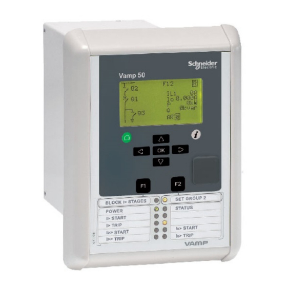
2.1. Relay front panel The figure below shows, as an example, the front panel of the overcurrent and earthfault protection relay VAMP 50 and the location of the user interface elements used for local control. VAMP50Front Figure 2.1-1. Relay front panel 1. -
Page 6: Display
Figure 2.1.1-2 Sections of the LCD dot matrix display 1. Main menu column 2. The heading of the active menu 3. The cursor of the main menu 4. Possible navigating directions (push buttons) 5. Measured/setting parameter 6. Measured/set value VAMP 24h support phone +358 (0)20 753 3264 VM50.EN004... -
Page 7: Menu Navigation And Pointers
CURRENTS 4. Further, each display holds the measured values and units of one or more quantities or parameters, e.g. Ilmax 300A. VM50.EN004 VAMP 24h support phone +358 (0)20 753 3264... -
Page 8: Keypad
6. Function keys 1 and 2 (F1 / F2) F1 toggles Virtual Input 1 (VI1) On/Off F2 toggles Virtual Input 2 (VI2) On/Off NOTE! The term, which is used for the buttons in this manual, is inside the brackets. VAMP 24h support phone +358 (0)20 753 3264 VM50.EN004... -
Page 9: Operation Indicators
The readability of the LCD varies with the brightness and the temperature of the environment. The contrast of the display can be adjusted via the PC user interface, see chapter 3. VM50.EN004 VAMP 24h support phone +358 (0)20 753 3264... -
Page 10: Local Panel Operations
The active main menu selection is indicated with black background color. The possible navigating directions in the menu are shown in the upper-left corner by means of black triangular symbols. VAMP 24h support phone +358 (0)20 753 3264 VM50.EN004... - Page 11 The general menu structure is shown in Figure 2.2.1-2. The menu is dependent on the user’s configuration and the options according the order code. For example only the enabled protection stages will appear in the menu. VM50.EN004 VAMP 24h support phone +358 (0)20 753 3264...
- Page 12 Thermal overload stage Io> 1st earth fault stage 50N/51N Io>> 2nd earth fault stage 50N/51N Io>>> 3rd earth fault stage 50N/51N Io>>>> 4th earth fault stage 50N/51N Prg1 1st programmable stage VAMP 24h support phone +358 (0)20 753 3264 VM50.EN004...
-
Page 13: Menu Structure Of Protection Functions
Detailed protocol configuration is done with VAMPSET. VAMP51 and VAMP52 2.2.2. Menu structure of protection functions The general structure of all protection function menus is similar although the details do differ from stage to stage. As an VM50.EN004 VAMP 24h support phone +358 (0)20 753 3264... - Page 14 Iv> SGrpDI I > Force Figure 2.2.2-1 First menu of I>> 50/51 stage This is the status, start and trip counter and setting group menu. The content is: Status – The stage is not detecting any fault at the moment. The stage can also be forced to pick-up or trip is the operating level is “Configurator”...
- Page 15 2.50xIn CBWE t>> 0.60s Figure 2.2.2-2 Second menu(next on the right) of I>> 50/51 stage This is the main setting menu. The content is: Stage setting group 1 These are the group 1 setting values. The other setting group can be seen by pressing push buttons ENTER and then RIGHT or LEFT.
- Page 16 Load 0.99xIn EDly SetGrp Figure 2.2.2-3 Third and last menu (next on the right) of I>> 50/51 stage This is the menu for registered values by the I>> stage. Fault logs are explained in chapter 2.2.4. FAULT LOG 1 This is the latest of the eight available logs.
-
Page 17: Setting Groups
(the LEFT key is used when the active setting group is 2 and the RIGHT key is used when the active setting group is 1). Figure 2.2.3-2 Example of I> setting submenu VM50.EN004 VAMP 24h support phone +358 (0)20 753 3264... -
Page 18: Fault Logs
(See Figure 2.2.4-2, Log2 = log two). The log two is selected by pressing the RIGHT key once. Figure 2.2.4-2 Example of selected fault log VAMP 24h support phone +358 (0)20 753 3264 VM50.EN004... -
Page 19: Operating Levels
Opening: Default password is 2 Setting state: Push ENTER Closing: The level is automatically closed after 10 minutes idle time. Giving the password 9999 can also close the level. VM50.EN004 VAMP 24h support phone +358 (0)20 753 3264... - Page 20 Get the serial number of the relay (Example: 12345) Send both the numbers to vampsupport@vamp.fi and ask for a password break. A device specific break code is sent back to you. That code will be valid for the next two weeks.
-
Page 21: Operating Measures
2. Select the virtual input object (empty or black square) 3. The dialog opens 4. Select “VIon” to activate the virtual input or select “VIoff” to deactivate the virtual input VM50.EN004 VAMP 24h support phone +358 (0)20 753 3264... -
Page 22: Measured Data
IL3 [%] IL1har HARMONICS of IL1 Harmonics of phase current IL1 [%] IL2har HARMONICS of IL2 Harmonics of phase current IL2 [%] IL3har HARMONICS of IL3 Harmonics of phase current IL3 [%] VAMP 24h support phone +358 (0)20 753 3264 VM50.EN004... -
Page 23: Reading Event Register
It is possible to set the order in which the events are sorted. If the “Order” -parameter is set to “New-Old”, then the first event in the EVENT LIST is the most recent event. VM50.EN004 VAMP 24h support phone +358 (0)20 753 3264... -
Page 24: Forced Control (Force)
10. Repeat the steps 1...4 to exit the Force function. 11. Push the CANCEL key to return to the main menu. NOTE! All the interlockings and blockings are bypassed when the force control is used. VAMP 24h support phone +358 (0)20 753 3264 VM50.EN004... -
Page 25: Configuration And Parameter Setting
ENTER key again. The parameter can now be set. When the parameter change is confirmed with the ENTER key, a [RESTART]- text appears to the top-right corner of the display. This means that auto-resetting is VM50.EN004 VAMP 24h support phone +358 (0)20 753 3264... -
Page 26: Parameter Setting
Inom Inom 200A Io> Isec Isec 100A Io> > Ionom Ionom 100A 1.0A CBFP Iosec Iosec 1.0A 1.0A CONF Ioinp CONF Ioinp 1.0A Edit VALUE CHANGE CT primary Figure 2.4.1-1.Changing parameters VAMP 24h support phone +358 (0)20 753 3264 VM50.EN004... -
Page 27: Setting Range Limits
Recording time (Time) Pre trig time (PreTrig) Manual trigger (ManTrig) Count of ready records (ReadyRec) REC. CHANNELS Add a link to the recorder (AddCh) Clear all links (ClrCh) VM50.EN004 VAMP 24h support phone +358 (0)20 753 3264... -
Page 28: Configuring Digital Inputs Di
Trip and application specific alarm leds A, B, C, D, E, F, G and H (that is, the output relay matrix). NOTE! The amount of Trip and Alarm relays depends on the relay type and optional hardware. VAMP 24h support phone +358 (0)20 753 3264 VM50.EN004... -
Page 29: Configuring Analogue Outputs Ao (Option)
The relay includes several protection functions. However, the processor capacity limits the number of protection functions that can be active at the same time. VM50.EN004 VAMP 24h support phone +358 (0)20 753 3264... -
Page 30: Configuration Menu Conf
Rated Uo VT secondary voltage (Uosec) Voltage measuring mode (Umode) DEVICE INFO Relay type (Type VAMP 5X) Serial number (SerN) Software version (PrgVer) Bootcode version (BootVer) VAMP 24h support phone +358 (0)20 753 3264 VM50.EN004... -
Page 31: Protocol Menu Bus
Communication time-out error counter [Tout]. Information of bit rate/data bits/parity/stop bits. This value is not directly editable. Editing is done in the appropriate protocol setting menus. The counters are useful when testing the communication. VM50.EN004 VAMP 24h support phone +358 (0)20 753 3264... - Page 32 Modbus bit rate [bit/s]. Default is "9600". Parity [Parity]. Default is "Even". For details see the technical description part of the manual. VAMP 24h support phone +358 (0)20 753 3264 VM50.EN004...
- Page 33 Minimum measurement response interval [MeasInt]. ASDU6 response time mode [SyncRe]. For details see the technical description part of the manual. IEC 103 DISTURBANCE RECORDINGS For details see the technical description part of the manual. VM50.EN004 VAMP 24h support phone +358 (0)20 753 3264...
- Page 34 Bit rate [bit/s]. Default is “9600”. [Parity]. Link layer address for this device [LLAddr]. ASDU address [ALAddr]. For further details see the technical description part of the manual. VAMP 24h support phone +358 (0)20 753 3264 VM50.EN004...
-
Page 35: Single Line Diagram Editing
Furthermore, the interlocking between objects can be configured in the same blocking matrix of the VAMPSET software. For more information, please refer to the VAMPSET manual (VMV.EN0xx). VM50.EN004 VAMP 24h support phone +358 (0)20 753 3264... -
Page 36: Vampset Pc Software
Optional hardware is required for Ethernet connection. There is a free of charge PC program called VAMPSET available for configuration and setting of VAMP relays. Please download the latest VAMPSET.exe from our web page www.vamp.fi. For more information about the VAMPSET software, please refer to the user’s manual with the code... - Page 37 2.3. General features of protection stages ......45 2.4. Relay function dependencies ........48 2.4.1. Application modes..........48 2.4.2. Current protection function dependencies..49 2.5. Overcurrent protection I> (50/51) ........ 49 2.5.1. Remote controlled overcurrent scaling ....53 2.6. Broken line protection I > (46R)......... 54 2.7.
- Page 38 6.2.2. Modbus TCP and Modbus RTU ......173 6.2.3. Profibus DP ............. 174 6.2.4. SPA-bus..............176 6.2.5. IEC 60870-5-103 ............. 176 6.2.6. DNP 3.0 ..............178 6.2.7. IEC 60870-5-101 ............. 180 6.2.8. Ethernet port............181 VAMP 24h support phone +358 (0)20 753 3264 VM50.EN004...
- Page 39 8.8.2. VAMP 51..............207 8.8.3. VAMP 52..............208 8.9. Block diagrams of optional arc modules ....209 8.10. Connection examples..........210 8.10.1. VAMP 50 / VAMP 51 ..........210 8.10.2. VAMP 52..............211 9. Technical data ..............214 9.1. Connections ..............214 9.1.1.
- Page 40 9.3.5. Circuit-breaker failure protection ...... 223 9.3.6. Arc fault protection (option) ......223 10. Abbreviations and symbols ..........225 11. Construction ...............227 12. Order information...............228 13. Revision history ..............229 14. Reference information ............230 VAMP 24h support phone +358 (0)20 753 3264 VM50.EN004...
- Page 41 This part of the user manual describes the protection functions, provides a few application examples and contains technical data. The numerical VAMP device includes all the essential overcurrent and earthfault protection functions needed. Further, the device includes several programmable functions,...
- Page 42 The main components are the energizing inputs, digital input elements, output relays, A/D converters and the micro controller including memory circuits. Further, a device contains a power supply unit and a human-machine interface (HMI). VAMP 24h support phone +358 (0)20 753 3264 VM50.EN004...
- Page 43 Figure 1.2-3 shows a principle diagram of a single-phase overvoltage or overcurrent function. Figure 1.2-1 Principle block diagram of the VAMP hardware Figure 1.2-2 Block diagram of signal processing and protection software Figure 1.2-3 Block diagram of a basic protection function VM50.EN004...
- Page 44 (phase-to-neutral voltage). 51F2 > Second harmonic O/C stage CBFP Circuit-breaker failure 50BF protection Prg1...8 Programmable stages Only VAMP51/52 50ARC/ ArcI>, ArcI > Optional arc fault protection (with an external module) 50NARC VAMP 24h support phone +358 (0)20 753 3264 VM50.EN004...
- Page 45 The start signal is issued when a fault has been detected. The trip signal is issued after the configured operation delay unless the fault disappears before the end of the delay time. VM50.EN004 VAMP 24h support phone +358 (0)20 753 3264...
- Page 46 The difference must be more than the retardation time of the incoming feeder relay plus the operating time of the outgoing feeder circuit breaker. VAMP 24h support phone +358 (0)20 753 3264 VM50.EN004...
- Page 47 (the dashed 40 ms pulse in the figure). In VAMP devices the retardation time is less than 50 Reset time (release time) Figure 2.3-2 shows an example of reset time i.e. release delay, when the relay is clearing an overcurrent fault.
- Page 48 The application mode can be changed with VAMPSET software or from CONF menu of the device. Changing the application mode requires configurator password. VAMP 24h support phone +358 (0)20 753 3264 VM50.EN004...
- Page 49 (DT) or inverse time operation characteristic (IDMT). The stages I>> and I>>> have definite time operation characteristic. By using the definite delay type and setting the delay to its minimum, an instantaneous (ANSI 50) operation is obtained. Figure 2.5-1 shows a functional block diagram of the I>...
- Page 50 (communication, logic) and manually. Figure 2.5-1 Block diagram of the three-phase overcurrent stage I>. Figure 2.5-2 Block diagram of the three-phase overcurrent stage I>> and I>>>. Parameters of the overcurrent stage I> (50/51) Parameter Value Unit Description...
- Page 51 See chapter 2.23. For details of setting ranges see chapter 9.3. Set = An editable parameter (password needed) C = Can be cleared to zero F = Editable when force flag is on VM50.EN004 VAMP 24h support phone +358 (0)20 753 3264...
- Page 52 2.5 Overcurrent protection I> (50/51) 2 Protection functions Technical description Parameters of the overcurrent stages I>>, I>>> (50/51) Parameter Value Unit Description Note Status Current status of the stage Blocked Start Trip SCntr Cumulative start counter TCntr Cumulative trip counter...
- Page 53 TCP –protocol. When changing the scaling factor remotely value of 1% is equal to 1. Check the correct modbus address for this application from the vampset or from the communication parameter list. VM50.EN004 VAMP 24h support phone +358 (0)20 753 3264...
- Page 54 8.10. The unbalance protection has definite time operation characteristic. , where K VAMP 24h support phone +358 (0)20 753 3264 VM50.EN004...
- Page 55 The current unbalance protection is based on the negative sequence of the base frequency phase currents. Both definite time and inverse time characteristics are available. VM50.EN004 VAMP 24h support phone +358 (0)20 753 3264...
- Page 56 (chapter 2.21). Setting groups There are two settings groups available. Switching between setting groups can be controlled by digital inputs, virtual inputs (communication, logic) and manually. VAMP 24h support phone +358 (0)20 753 3264 VM50.EN004...
- Page 57 Automatically reset by a 5- minute timeout. I2/Imot %Imot The supervised value. I2> %Imot Pick-up setting t> Definite operation time (Type=DT) Type Definite time Inverse time (Equation 2.7-1) Delay multiplier (Type =INV) VM50.EN004 VAMP 24h support phone +358 (0)20 753 3264...
- Page 58 > (48) The stall protection unit I > measures the fundamental frequency component of the phase currents. Stage I > can be configured for definite time or inverse time operation characteristic. VAMP 24h support phone +358 (0)20 753 3264 VM50.EN004...
- Page 59 Block Trip ³1 & Register event Inverse delay Motor nom. Delay Definite / inverse Enable events start current time Figure 2.9-2 Block diagram of the stall protection stage I >. VM50.EN004 VAMP 24h support phone +358 (0)20 753 3264...
- Page 60 The stage will give a start signal when the second last start has been done. The trip signal is normally activated and released when there are no starts left. Figure 2.10-1 shows an application. VAMP 24h support phone +358 (0)20 753 3264 VM50.EN004...
- Page 61 Tot Mot Number of total motor starts Strs Mot Strs/h Number of motor starts in last hour El. Time Elapsed time from the last from mot motor start Strt VM50.EN004 VAMP 24h support phone +358 (0)20 753 3264...
- Page 62 If the fault situation remains on longer than the user's operation time delay setting, a trip signal is issued. VAMP 24h support phone +358 (0)20 753 3264 VM50.EN004...
- Page 63 I0 signal. This mode is used with unearthed networks. The trip area is a half plane as drawn in Figure 2.12-2. The base angle is usually set to zero degrees. VM50.EN004 VAMP 24h support phone +358 (0)20 753 3264...
- Page 64 Two independent stages > and I >>. There are two separately adjustable stages: I Both the stages can be configured for definite time delay (DT) or inverse time delay operation time. VAMP 24h support phone +358 (0)20 753 3264 VM50.EN004...
- Page 65 Figure 2.12-2. Operation characteristic of the directional earth fault protection in Res or Cap mode. Res mode can be used with compensated networks and Cap mode is used with ungrounded networks. VM50.EN004 VAMP 24h support phone +358 (0)20 753 3264...
- Page 66 Automatically reset by a 5- minute timeout. The supervised value according the parameter IoCalc "Input" below. IoPeak > only) IoRes Resistive part of I (only when "InUse"=Res) IoCap Capacitive part of I (only when "InUse"=Cap) VAMP 24h support phone +358 (0)20 753 3264 VM50.EN004...
- Page 67 Fixed to Capacitive characteristic Controlled by digital input DI1, DI2 Controlled by virtual input VI1..4 InUse Selected submode in mode ResCap. Mode is not ResCap Submode = resistive Submode = capacitive VM50.EN004 VAMP 24h support phone +358 (0)20 753 3264...
- Page 68 If the fault situation remains on longer than the user's operation time delay setting, a trip signal is issued. VAMP 24h support phone +358 (0)20 753 3264 VM50.EN004...
- Page 69 Short earth faults make the protection to start (pick up), but will not cause trip. When starting happens often enough, such intermittent faults can be cleared using the intermittent time setting. VM50.EN004 VAMP 24h support phone +358 (0)20 753 3264...
- Page 70 2.23 for more information. Setting groups There are two settings groups available for each stage. Switching between setting groups can be controlled by digital inputs, virtual inputs (communication, logic) and manually. VAMP 24h support phone +358 (0)20 753 3264 VM50.EN004...
- Page 71 Delay curve family: Definite time Inverse time. See chapter 2.23. IEEE IEEE2 PrgN Type Delay type. Definite time Inverse time. See chapter 2.23. Paramet t> Definite operation time (for definite time only) VM50.EN004 VAMP 24h support phone +358 (0)20 753 3264...
- Page 72 Automatically reset by a 5- minute timeout. The supervised value according the parameter IoCalc “Input” below. Io>> Pick-up value scaled to primary value Io>>> Io>>>> VAMP 24h support phone +358 (0)20 753 3264 VM50.EN004...
- Page 73 Although a single transient fault usually self extinguishes within less than one millisecond, in most cases a new fault happens when the phase-to-earth voltage of the faulty phase has recovered (Figure 2.14-1). VM50.EN004 VAMP 24h support phone +358 (0)20 753 3264...
- Page 74 U measurement. pick-up sensitivity The sampling time interval of the relay is 625 s at 50 Hz (32 samples/cycle). The I current spikes can be quite short compared to this sampling interval. Fortunately the current...
- Page 75 20 ms and a start signal is issued. If the time between successive faults is less than 40 ms, a trip signal is issued when the operation time is full. VM50.EN004 VAMP 24h support phone +358 (0)20 753 3264...
- Page 76 No trip will happen. The lower start and trip status lines show another case with intermittent time setting 0.12 s. In this case a trip signal will be issued at t=0.87 s. VAMP 24h support phone +358 (0)20 753 3264 VM50.EN004...
- Page 77 Automatically reset after a five minute timeout. The detected I value according the parameter "Input" below. The measured U value. = 100 % Uo> pick up level. U = 100 % VM50.EN004 VAMP 24h support phone +358 (0)20 753 3264...
- Page 78 The attenuation of the third harmonic is more than 60 dB. This is essential, because 3n harmonics exist between the neutral point and earth also when there is no earth fault. VAMP 24h support phone +358 (0)20 753 3264 VM50.EN004...
- Page 79 There are two settings groups available for both stages. Switching between setting groups can be controlled by digital inputs, virtual inputs (communication, logic) and manually. Figure 2.15-1. Block diagram of the zero sequence voltage stages U > and >> VM50.EN004 VAMP 24h support phone +358 (0)20 753 3264...
- Page 80 Time stamp of the recording, date hh:mm:ss.ms Time stamp, time of day Fault voltage relative to Un/3 EDly Elapsed time of the operating time setting. 100% = trip SetGrp Active setting group during fault VAMP 24h support phone +358 (0)20 753 3264 VM50.EN004...
- Page 81 TRIP cable. I depends of the given service factor k and ambient temperature and settings I and I according the max40 max70 following equation. VM50.EN004 VAMP 24h support phone +358 (0)20 753 3264...
- Page 82 In this example = 30 minutes, k = 1.06 and k = 1 and the current has been zero for a long time and thus the initial temperature rise is 0 %. At time = 50 minutes the current changes to 0.85xI...
- Page 83 Allowed overload (service factor) Alarm Alarm level Thermal time constant ctau xtau Coefficient for cooling time constant. Default = 1.0 kTamb xImode Ambient temperature corrected max. allowed continuous current VM50.EN004 VAMP 24h support phone +358 (0)20 753 3264...
- Page 84 U>> is used for the actual trip. The overvoltage setting value for stage U>> has to be higher than the setting value for stage U> to ensure an alarm before trip. VAMP 24h support phone +358 (0)20 753 3264 VM50.EN004...
- Page 85 0.10 (U>>, U>>>) 0.06 … 300.00 (U>>>) ReleaseDly 0.06 … 300.0 Release delay [s] (only U>) Hysteresis 0.1 … 20.0 Deadband (only U>) S_On Enabled; Enabled Start on event Disabled VM50.EN004 VAMP 24h support phone +358 (0)20 753 3264...
- Page 86 If the fault appears again before the delay time has elapsed, the trip counter continues from the previous fault value. This means that the function trips after a certain number of instantaneous faults. VAMP 24h support phone +358 (0)20 753 3264 VM50.EN004...
- Page 87 Deadband (only U<) S_On Enabled; Enabled Start on event Disabled S_Off Enabled; Enabled Start off event Disabled T_On Enabled; Enabled Trip on event Disabled T_Off Enabled; Enabled Trip off event Disabled VM50.EN004 VAMP 24h support phone +358 (0)20 753 3264...
- Page 88 2ndHarm & > Start & Register event Block Trip & Register event Setting Delay Enable events 2.Harm Figure 2.19-1 Block diagram of the second harmonic stage. VAMP 24h support phone +358 (0)20 753 3264 VM50.EN004...
- Page 89 The CBFP stage is supervising all the protection stages using the same selected trip relay, since it supervises the control signal of this relay. See chapter 5.4 for details about the output matrix and the trip relays. VM50.EN004 VAMP 24h support phone +358 (0)20 753 3264...
- Page 90 CBFP (50BF) Parameter Value Unit Description yyyy-mm-dd Time stamp of the recording, date hh:mm:ss.ms Time stamp, time of day EDly Elapsed time of the operating time setting. 100% = trip VAMP 24h support phone +358 (0)20 753 3264 VM50.EN004...
- Page 91 Hyster Dead band (hysteresis) NoCmp Only used with compare mode under (‘<’). This is the limit to start the comparison. Signal values under NoCmp are not regarded as fault. VM50.EN004 VAMP 24h support phone +358 (0)20 753 3264...
- Page 92 There are two settings groups available. Switching between setting groups can be controlled by digital inputs, virtual inputs (communication, logic) and manually. There are two identical stages available with independent setting parameters. VAMP 24h support phone +358 (0)20 753 3264 VM50.EN004...
- Page 93 F = Editable when force flag is on Recorded values of the latest eight faults There is detailed information available of the eight latest faults: Time stamp, fault value and elapsed delay. VM50.EN004 VAMP 24h support phone +358 (0)20 753 3264...
- Page 94 The arc option card is inserted in the upper option card slot in the back of the VAMP 50 protection relay. The card is fastened to the relay with two screws. The optional arc protection card includes two arc sensor channels.
- Page 95 BO, indicators etc. offered by the output matrix (See chapter 5.4). BI is a dry input for 48 Vdc signal from binary outputs of other VAMP relays or dedicated arc protection devices by VAMP.
- Page 96 Recorded values of the latest eight faults There is detailed information available of the eight latest faults: Time stamp, fault type, fault value, load current before the fault and elapsed delay. VAMP 24h support phone +358 (0)20 753 3264 VM50.EN004...
- Page 97 This mode is activated by setting delay type to ‘Parameters’, and then editing the delay function parameters A ... E. See chapter 2.23.2. VM50.EN004 VAMP 24h support phone +358 (0)20 753 3264...
- Page 98 20x setting and I 250 A 12.5 A 0Calc 50 A 2.5 A 10 A 0.5 A 0.2 A 0.1 A VAMP 24h support phone +358 (0)20 753 3264 VM50.EN004...
- Page 99 The inverse time setting error signal will be activated, if the delay category is changed and the old delay type doesn't exist in the new category. See chapter 2.23 for more details. VM50.EN004 VAMP 24h support phone +358 (0)20 753 3264...
- Page 100 Ipickup = User’s pick up setting A, B Constants parameters according Table 2.23.1-2. There are three different delay types according IEC 60255-3, Normal inverse (NI), Extremely inverse (EI), Very inverse (VI) VAMP 24h support phone +358 (0)20 753 3264 VM50.EN004...
- Page 101 The operation time in this example will be 5 seconds. The same result can be read from Figure 2.23.1-1. Figure 2.23.1-1 IEC normal inverse Figure 2.23.1-2 IEC extremely delay. inverse delay. VM50.EN004 VAMP 24h support phone +358 (0)20 753 3264...
- Page 102 Table 2.23.1-3. The IEEE standard defines inverse delay for both trip and release operations. However, in the VAMP relay only the trip time is inverse according the standard but the release time is constant. The operation delay depends on the measured value and other parameters according Equation 2.23.1-2.
- Page 103 The operation time in this example will be 1.9 seconds. The same result can be read from Figure 2.23.1-8. Figure 2.23.1-5 ANSI/IEEE long Figure 2.23.1-6 ANSI/IEEE long time inverse delay time very inverse delay VM50.EN004 VAMP 24h support phone +358 (0)20 753 3264...
- Page 104 A quite popular approximation is Equation 2.23.1-3, which in VAMP relays is called IEEE2. Another name could be IAC, because the old General Electric IAC relays have been modeled using the same equation.
- Page 105 Table 2.23.1-4. The old electromechanical induction disc relays have inverse delay for both trip and release operations. However, in VAMP relays only the trip time is inverse the release time being constant. The operation delay depends on the measured value and other parameters according Equation 2.23.1-3.
- Page 106 Figure 2.23.1-11. Figure 2.23.1-11 IEEE2 moderately Figure 2.23.1-12 IEEE2 normal inverse delay inverse delay Figure 2.23.1-13 IEEE2 very inverse Figure 2.23.1-14 IEEE2 extremely delay inverse delay VAMP 24h support phone +358 (0)20 753 3264 VM50.EN004...
- Page 107 The operation time in this example will be 2.3 seconds. The same result can be read from Figure 2.23.1-15. Example for Delay type RXIDG: = 0.50 = 4 pu = 2 pu pickup RXIDG VM50.EN004 VAMP 24h support phone +358 (0)20 753 3264...
- Page 108 The operation time in this example will be 3.9 seconds. The same result can be read from Figure 2.23.1-16. Figure 2.23.1-15 Inverse delay of Figure 2.23.1-16 Inverse delay of type RI. type RXIDG. VAMP 24h support phone +358 (0)20 753 3264 VM50.EN004...
- Page 109 The minimum definite time delay start latest, when the measured value is twenty times the setting. However, there are limitations at high setting values due to the measurement range. See chapter 2.23 for more details. VM50.EN004 VAMP 24h support phone +358 (0)20 753 3264...
- Page 110 The minimum definite time delay start latest, when the measured value is twenty times the setting. However, there are limitations at high setting values due to the measurement range. See chapter 2.23 for more details. VAMP 24h support phone +358 (0)20 753 3264 VM50.EN004...
- Page 111 Such a code and the corresponding time stamp is called an event. The event codes are listed in a separate document “Modbus_Profibus_Spabus_event.pdf”. As an example of information included with a typical event an overcurrent trip event of the first 50/51 stage I> is shown in the following table. EVENT Description...
- Page 112 The triggering signal is selected in the output matrix (vertical signal DR). The recording can also be triggered manually. All recordings are time stamped. VAMP 24h support phone +358 (0)20 753 3264 VM50.EN004...
- Page 113 PreTrig Amount of recording data before the trig moment MaxLen Maximum time setting. This value depends on sample rate, number and type of the selected channels and the configured recording length. VM50.EN004 VAMP 24h support phone +358 (0)20 753 3264...
- Page 114 Current unbalance [xI Average (IL1 + IL2 + IL3)/3 Digital outputs Digital inputs TanFii THDIL1 Total harmonic distortion of IL1 THDIL2 Total harmonic distortion of IL2 THDIL3 Total harmonic distortion of IL3 VAMP 24h support phone +358 (0)20 753 3264 VM50.EN004...
- Page 115 It is also possible to use the cold load detection signal to block any set of protection stages for a given time. VM50.EN004 VAMP 24h support phone +358 (0)20 753 3264...
- Page 116 Now we have a cold load activation which lasts as long as the operation time was set or as long as the current stays above the pick-up setting. Figure 3.3-1 Functionality of cold load / inrush current feature. VAMP 24h support phone +358 (0)20 753 3264 VM50.EN004...
- Page 117 0.0 … 10.0 Lower setting for CT supervisor t> 0.02 … 0.10 Operation delay 600.0 CT on On; Off CT supervisor on event CT off On; Off CT supervisor off event VM50.EN004 VAMP 24h support phone +358 (0)20 753 3264...
- Page 118 The points 4...8 are not needed for the CB in Figure 3.5-1. Thus they are set to 100 kA and one operation in the table to be discarded by the algorithm. VAMP 24h support phone +358 (0)20 753 3264 VM50.EN004...
- Page 119 When the "operations left" i.e. the number of remaining operations, goes under the given alarm limit, an alarm signal is issued to the output matrix. Also an event is generated depending on the event enabling. VM50.EN004 VAMP 24h support phone +358 (0)20 753 3264...
- Page 120 = row 2...7 in Table 3.5-1. = corresponding current. k = row 2...7 in Table 3.5-1. = permitted operations. k = row 2...7 in Table 3.5-1. = corresponding current. k = row 2...7 in Table 3.5-1. VAMP 24h support phone +358 (0)20 753 3264 VM50.EN004...
- Page 121 3.5-1. Indeed, the figure shows that at 6 kA the operation count is between 900 and 1000. A useful alarm level for operation- left, could be in this case for example 50 being about five per cent of the maximum.
- Page 122 Thus Alarm2 counters for phases L1 and L2 are decremented by 3. In phase L1 the currents is less than the alarm limit current 6 kA. For such currents the decrement is one. VAMP 24h support phone +358 (0)20 753 3264 VM50.EN004...
- Page 123 'Alarm2 on' event enabling Al2Off 'Alarm2 off' event enabling Clear Clearing of cycle counters Clear Set = An editable parameter (password needed) The breaker curve table is edited with VAMPSET. VM50.EN004 VAMP 24h support phone +358 (0)20 753 3264...
- Page 124 Pulse length of active DURATION exported energy 100 … 5000 Pulse length of reactive exported energy 100 … 5000 Pulse length of active imported energy 100 … 5000 Pulse length of reactive imported energy VAMP 24h support phone +358 (0)20 753 3264 VM50.EN004...
- Page 125 /417 h = 14 a. Example 4. Average active exported power is 1900 kW. Peak active exported power is 50 MW. Pulse size is 10 kWh. The average pulse frequency will be 1900/10 = 190 pulses/h. The peak pulse frequency will be 50000/10 = 5000 pulses/h.
- Page 126 Reactive imported Pulse counter input energy pulses e-pulseconf3 Figure 3.6-4. Application example of wiring the energy pulse outputs to a PLC having common minus and an internal wetting voltage. VAMP 24h support phone +358 (0)20 753 3264 VM50.EN004...
- Page 127 1000, if some other period than one week has been used. For example if the drift has been 37 seconds in 14 days, the relative drift is 37*1000/(14*24*3600) = 0.0306 ms/s. VM50.EN004 VAMP 24h support phone +358 (0)20 753 3264...
- Page 128 UTC time zone for SNTP +14.00 synchronization. Note: This is a decimal number. For example for state of Nepal the time zone 5:45 is given as 5.75 Daylight saving time for SNTP VAMP 24h support phone +358 (0)20 753 3264 VM50.EN004...
- Page 129 SyncDI setting. When rising edge is detected from the selected input, system clock is adjusted to the nearest minute. Length of digital input pulse should be at least 50 ms. Delay of the selected digital input should be set to zero.
- Page 130 Output matrix out signal LA LedB, Output matrix out signal LB LedC, Output matrix out signal LC LedDR Output matrix out signal DR VO1...VO6 Virtual outputs Started at Date and time of the last activation VAMP 24h support phone +358 (0)20 753 3264 VM50.EN004...
- Page 131 (Set) = An informative value which can be edited as well. 3.9. Timers The VAMP protection platform includes four settable timers that can be used together with the user's programmable logic or to control setting groups and other applications that require actions based on calendar time.
- Page 132 “clearing delay“ has passed. The combined o/c status referres to the following over current stages: I>, I>>, I>>>, I >, I >>, I >>> and I >>>>. VAMP 24h support phone +358 (0)20 753 3264 VM50.EN004...
- Page 133 Several events are enabled Several events of an increasing fault is disabled ClrDly 0 ... 65535 Duration for active alarm status AlrL1, Alr2, AlrL3 and OCs VM50.EN004 VAMP 24h support phone +358 (0)20 753 3264...
- Page 134 Not used with Spabus, because Spabus masters usually don't like to have unpaired On/Off events. **) Used with SPA-bus protocol, because most SPA-bus masters do need an off-event for each corresponding on-event. VAMP 24h support phone +358 (0)20 753 3264 VM50.EN004...
- Page 135 (IF) output relay functions on a working current principle. This means that the IF relay is energized when the auxiliary supply is on and no internal fault is detected. VM50.EN004 VAMP 24h support phone +358 (0)20 753 3264...
- Page 136 E2prom error 0 (LSB) +12V Internal voltage fault SelfDiag4 ComBuff BUS: buffer error The error code is displayed in self diagnostic events and on the diagnostic menu on local panel and VAMPSET. VAMP 24h support phone +358 (0)20 753 3264 VM50.EN004...
- Page 137 0 – 250 A I 7.5 A 0.5 % of value or 15 mA Inaccuracy I > 7.5 A 3 % of value The specified frequency range is 45 Hz – 65 Hz. VM50.EN004 VAMP 24h support phone +358 (0)20 753 3264...
- Page 138 RMS voltages The device calculates the RMS value of each voltage input. The minimum and the maximum of RMS values are recorded and stored (see chapter 4.5). VAMP 24h support phone +358 (0)20 753 3264 VM50.EN004...
- Page 139 The relay calculates average i.e. demand values of phase currents I and power values S, P and Q. The demand time is configurable from 10 minutes to 30 minutes with parameter "Demand time". VM50.EN004 VAMP 24h support phone +358 (0)20 753 3264...
- Page 140 Demand values of phase currents, rms values (rms value) PFda Power factor demand value The clearing parameter "ClrMax" is common for all these values. Parameters Parameter Value Description ClrMax Reset all minimum and maximum values Clear VAMP 24h support phone +358 (0)20 753 3264 VM50.EN004...
- Page 141 The device is connected to zero sequence voltage. Directional earth fault protection is available. Line voltage measurement, energy measurement and over- and undervoltage protection are not possible (see Figure 4.7-1 and Figure 8.10.2-1). VM50.EN004 VAMP 24h support phone +358 (0)20 753 3264...
- Page 142 Directional earth fault protection is not possible (see Figure 4.7-3 and Figure 8.10.2-3). VAMP 52 L2 L3 "Uo" Figure 4.7-1 VAMP 52 Broken delta connection in voltage measurement mode “U ”. VAMP 52 L1 L2 L3 "1LL"...
- Page 143 (line-to-line voltage, see Figure 8.10.2-2) or 1LN (phase-to-neutral voltage, see Figure 8.10.2-3). The power calculations in the VAMP 52 are dependant on the voltage measurement mode. The formulas used by the VAMP 52 for power calculations are found in this chapter...
- Page 144 0° +cap Forward capacitive power Reverse inductive power current is leading current is leading cos = + cos = PF = PF = + PQ_Quadrants Figure 4.9-2 Quadrants of power plane VAMP 24h support phone +358 (0)20 753 3264 VM50.EN004...
- Page 145 The scaling is done using the given CT, VT in feeder mode and furthermore motor name plate values in motor mode. The following scaling equations are useful when doing secondary testing. VM50.EN004 VAMP 24h support phone +358 (0)20 753 3264...
- Page 146 Residual current (3I excluding ArcI> stage scaling and phase current scaling for ArcI> stage secondary per unit MODE MODE per unit secondary VAMP 24h support phone +358 (0)20 753 3264 VM50.EN004...
- Page 147 Example 6: Per unit to secondary for residual current. Input is I = 50/1 The relay setting is 0.03 pu = 3 %. Secondary current is = 0.03x1 = 30 mA VM50.EN004 VAMP 24h support phone +358 (0)20 753 3264...
- Page 148 = 3x58x12000/110 = 10902 V Example 3: Primary to secondary. Voltage measurement mode is "1LL". VT = 12000/110 The relay displays U = 10910 V. Secondary voltage is U = 10910x110/12000 = 100 V VAMP 24h support phone +358 (0)20 753 3264 VM50.EN004...
- Page 149 Example 3: Per unit to secondary. Voltage measurement mode is "1LL". VT = 12000/110 The relay displays 1.00 pu = 100 %. Secondary voltage is = 1.00x110x11000/12000 = 100.8 V VM50.EN004 VAMP 24h support phone +358 (0)20 753 3264...
- Page 150 0 … 20 mA. Available couplings to the analog output: IL1, IL2, IL2 F IL Io, IoCalc U12 (only in VAMP52) UL1 (only in VAMP52) VAMP 24h support phone +358 (0)20 753 3264 VM50.EN004...
- Page 151 Figure 4.12.1-1. Example of mA scaling for IL, average of the three phase currents. At 0 A the transducer ouput is 0 mA, at 300 A the output is 20 mA VM50.EN004 VAMP 24h support phone +358 (0)20 753 3264...
- Page 152 Names for DO on max. 32 VAMPSET screens. Default characters "Trip relay n", n=1...4 or "Alarm relay n", n=1 Set = An editable parameter (password needed) F = Editable when force flag is on VAMP 24h support phone +358 (0)20 753 3264 VM50.EN004...
- Page 153 For normal closed contacts (NC) Active edge is 10 Alarm display No pop-up display Alarm pop-up display is activated at active DI edge On event Active edge event enabled Active edge event disabled VM50.EN004 VAMP 24h support phone +358 (0)20 753 3264...
- Page 154 Virtual outputs are shown in the output matrix and the block matrix. Virtual outputs can be used with the user's programmable logic and to change the active setting group etc. VAMP 24h support phone +358 (0)20 753 3264 VM50.EN004...
- Page 155 The selection of the input is done with the VAMPSET software under the menu "Release output matrix latches". Under the same menu, the "Release latches" parameter can be used for resetting. Figure 5.4-1 Output matrix. VM50.EN004 VAMP 24h support phone +358 (0)20 753 3264...
- Page 156 The connection of an object to specific output relays is done via an output matrix (object 1-6 open output, object 1-65 close output). There is also an output signal “Object failed”, which is activated if the control of an object fails. VAMP 24h support phone +358 (0)20 753 3264 VM50.EN004...
- Page 157 0.02 … 600 s changes If changing states takes longer than the time defined by “Object timeout” setting, object fails and “Object failure” matrix signal is set. Also undefined-event is generated. VM50.EN004 VAMP 24h support phone +358 (0)20 753 3264...
- Page 158 The selection of the L/R digital input is done in the “Objects” menu of the VAMPSET software. NOTE! A password is not required for a remote control operation. VAMP 24h support phone +358 (0)20 753 3264 VM50.EN004...
- Page 159 5 Control functions 5.7 Auto-reclose function (79) 5.7. Auto-reclose function (79) NOTE! Available in VAMP 51 and VAMP 52. The auto-reclose (AR) matrix in the following Figure 5.7-1 describes the start and trip signals forwarded to the auto- reclose function.
- Page 160 Each AR shot can be blocked with a digital input, virtual input or virtual output. Blocking input is selected with Block setting. When selected input is active the shot is blocked. A blocked VAMP 24h support phone +358 (0)20 753 3264 VM50.EN004...
- Page 161 (1…4 and critical). When final trip is generated, one of these signals is set according to the AR request which caused the final tripping. The final trip signal will stay active for 0.5 seconds and then resets automatically. VM50.EN004 VAMP 24h support phone +358 (0)20 753 3264...
- Page 162 AR AR2 final trip on event CRITri On; Off AR critical final trip off event AR1Tri On; Off AR AR1 final trip off event AR2Tri On; Off AR AR2 final trip off event VAMP 24h support phone +358 (0)20 753 3264 VM50.EN004...
- Page 163 AR2 Start delay setting for this shot Discr1 0.02 … 300.00 0.02 AR1 Discrimination time setting for this shot Discr2 0.02 … 300.00 0.02 AR2 Discrimination time setting for this shot VM50.EN004 VAMP 24h support phone +358 (0)20 753 3264...
- Page 164 Shot2 start counter Shot3 * Shot3 start counter Shot4 * Shot4 start counter Shot5 * Shot5 start counter *) There are 5 counters available for each one of the two AR signals. VAMP 24h support phone +358 (0)20 753 3264 VM50.EN004...
- Page 165 I> setting. 10. Reclaim time starts. After the reclaim time the AR sequence is successfully executed. The AR function moves to wait for a new AR request in shot 1. VM50.EN004 VAMP 24h support phone +358 (0)20 753 3264...
- Page 166 Maximum number of outputs is 20. Maximum number of input gates is 31. An input gate can include any number of inputs. For detailed information, please refer to the VAMPSET manual (VMV.EN0xx). VAMP 24h support phone +358 (0)20 753 3264 VM50.EN004...
- Page 167 PORT PORT Communication option Ethernet RS-232 FRONT PANEL Figure 6.1-1. Communication ports and connectors. The DSR signal from the front panel port selects the active connector for the RS232 local port. VM50.EN004 VAMP 24h support phone +358 (0)20 753 3264...
- Page 168 The default settings for the relay are 38400/8N1. The communication parameter display on the local display will show the active parameter values for the local port. Physical interface The physical interface of this port is USB. VAMP 24h support phone +358 (0)20 753 3264 VM50.EN004...
- Page 169 Clr = Clearing to zero is possible 1) The communication parameters are set in the protocol specific menus. For the local port command line interface the parameters are set in configuration menu. VM50.EN004 VAMP 24h support phone +358 (0)20 753 3264...
- Page 170 Clr = Clearing to zero is possible 1) The communication parameters are set in the protocol specific menus. For the local port command line interface the parameters are set in configuration menu. VAMP 24h support phone +358 (0)20 753 3264 VM50.EN004...
- Page 171 Clr = Clearing to zero is possible 1) The communication parameters are set in the protocol specific menus. For the local port command line interface the parameters are set in configuration menu. VM50.EN004 VAMP 24h support phone +358 (0)20 753 3264...
- Page 172 The protocols enable the transfer of the following type of data: events status information measurements control commands. clock synchronizing Settings (SPA-bus and embedded SPA-bus only) VAMP 24h support phone +358 (0)20 753 3264 VM50.EN004...
- Page 173 6.2 Communication protocols 6.2.1. PC communication PC communication is using a VAMP specified command line interface. The VAMPSET program can communicate using the local USB-port or using optional TCP/IP and ethernet interface. It is also possible to select SPA-bus protocol for the local port and configure the VAMPSET to embed the command line interface inside SPA-bus messages.
- Page 174 Device profile "Request mode" Using the request mode it is possible to read all the available data from the VAMP device and still use only a very short buffer for Profibus data transfer. The drawback is the slower overall speed of the data transfer and the need of increased data processing at the Profibus master as every data item must be separately requested by the master.
- Page 175 4) If the value is "", Profibus protocol has not been selected or the device has not restarted after protocol change or there is a communication problem between the main CPU and the Profibus ASIC. VM50.EN004 VAMP 24h support phone +358 (0)20 753 3264...
- Page 176 station initialization general interrogation clock synchronization and command transmission. It is not possible to transfer parameter data or disturbance recordings via the IEC 103 protocol interface. VAMP 24h support phone +358 (0)20 753 3264 VM50.EN004...
- Page 177 The function type and information number used in private range messages is configurable. This enables flexible interfacing to different master systems. For more information on IEC 60870-5-103 in Vamp devices refer to the “IEC103 Interoperability List” document. Parameters Parameter...
- Page 178 Additional information can be obtained from the “DNP 3.0 Device Profile Document” and “DNP 3.0 Parameters.pdf”. DNP 3.0 communication is activated via menu selection. RS- 485 interface is often used but also RS-232 and fibre optic interfaces are possible. VAMP 24h support phone +358 (0)20 753 3264 VM50.EN004...
- Page 179 Application layer confirmation mode EvOnly (default) DBISup Double-bit input support No (default) SyncMode 0 65535 Clock synchronization request interval. 0 = only at boot Set = An editable parameter (password needed) VM50.EN004 VAMP 24h support phone +358 (0)20 753 3264...
- Page 180 The IEC 60870-5-101 standard is derived from the IEC 60870-5 protocol standard definition. In Vamp devices, IEC 60870-5-101 communication protocol is available via menu selection. The Vamp unit works as a controlled outstation (slave) unit in unbalanced mode. Supported application functions include process data...
- Page 181 IEC 61850 protocol can be used to read / write static data from the relay to receive events and to receive / send GOOSE messages to other relays. IEC 61850 serve interface is capable of. VM50.EN004 VAMP 24h support phone +358 (0)20 753 3264...
- Page 182 T Selector 0 – 64000 Transport selector IED Name String Identifcation of the device. Each device must have unique name. Delete command Send command to clear dynamic all dynamic datasets datasets VAMP 24h support phone +358 (0)20 753 3264 VM50.EN004...
- Page 183 6.2 Communication protocols Application The following chapters illustrate the versatile functions of the overcurrent and earth-fault protection relays VAMP 50 and VAMP51 as well feeder and motor protection relay VAMP52 in different protection applications The relays can be used for line/feeder protection of medium voltage networks with grounded, low-resistance grounded, isolated or a compensated neutral point.
- Page 184 Alarm Trip vamp50app1 Figure 7.1-1 VAMP 50 or VAMP51 used in substation feeder protection The VAMP50 includes three-phase overcurrent protection, earth fault protection and fast arc protection. At the incoming feeder, the instantaneous stage I>>> of the VAMP feeder device is blocked with the start signal of the overcurrent stage.
- Page 185 Error Alarm Trip vamp50app2 Figure 7.1-2 VAMP 52 used in substation feeder protection in compensated network For the directional function of earth fault function, the status information (on/off) of the Petersen coil is routed to one of the digital inputs of the feeder device so that either I or I 0sin ...
- Page 186 Error Alarm Trip vamp50app3 Figure 7.2-1 VAMP 52 feeder/motor protection relay used in cable protection of an industry plant network VAMP 52 support directional earth fault protection and three- phase overcurrent protection which is required in a cable feeder. Furthermore, the thermal stage can be used to protect the cable against overloading.
- Page 187 By utilizing an auxiliary contact of the CB for the external resistor, also the auxiliary contact in the trip circuit can be supervised. VM50.EN004 VAMP 24h support phone +358 (0)20 753 3264...
- Page 188 CB position is double-lined. The digital input is in active state when the trip circuit is complete. Figure 7.3.1-2 Trip circuit supervision using a single digital input, when the circuit breaker is in open position. VAMP 24h support phone +358 (0)20 753 3264 VM50.EN004...
- Page 189 0 can be used for the R coil – 20 % = 88 V + 10 % = 121 V /P = 242 . coil VM50.EN004 VAMP 24h support phone +358 (0)20 753 3264...
- Page 190 A 0.5 W resistor will be enough for this short time peak power, too. However, if the trip relay is closed for longer time than a few seconds, a 1 W resistor should be used. VAMP 24h support phone +358 (0)20 753 3264 VM50.EN004...
- Page 191 Otherwise, a superfluous trip circuit fault alarm will follow after the trip contact operates, and the relay remains closed because of latching. Both digital inputs must have their own common potential. VM50.EN004 VAMP 24h support phone +358 (0)20 753 3264...
- Page 192 Figure 7.3.2-2 Trip circuit supervision with two digital inputs. The CB is in the open position. The two digital inputs are now in series. VAMP 24h support phone +358 (0)20 753 3264 VM50.EN004...
- Page 193 Figure 7.3.2-4 An example of logic configuration for trip circuit supervision with two dry digital inputs DI1 and DI2. Figure 7.3.2-5 An example of output matrix configuration for trip circuit supervision with two digital inputs. VM50.EN004 VAMP 24h support phone +358 (0)20 753 3264...
- Page 194 8.1 Rear panel view 8 Connections Technical description Connections 8.1. Rear panel view Figure 8.1-1 Connections on the rear panel of the VAMP 50, VAMP 51 and VAMP 52. Terminal X1 Symbol Description IL1(S1) Phase current L1 (S1) IL1(S1) Phase current L1 (S1)
- Page 195 Trip relays T1 – T4 (terminals X3: 10-17) Alarm relay A1 (terminals X3: 7-9) Self-supervision system output relay IF (terminals X3: 18- VM50.EN004 VAMP 24h support phone +358 (0)20 753 3264...
- Page 196 2= + 3= GND Option: IRIG-B 2-pole screw 1= Data connector 2= GND Option: RTD fiber Light Snap-in input connector Option: Ethernet Ethernet RJ-45 1=Transmit+ 2=Transmit- 3=Receive+ 4=Reserved 5=Reserved 6=Receive- 7=Reserved 8=Reserved VAMP 24h support phone +358 (0)20 753 3264 VM50.EN004...
- Page 197 Arc sensor 1 (VA 1 DA) Arc sensor 2 (VA 1 DA) The arc option card is inserted in the upper option card slot in the back of the VAMP 50 protection relay and the module is fasted to VAMP 50 with two screws. VM50.EN004...
- Page 198 The connection between the inputs and the output is selectable via the output matrix of the device. The binary output can be connected to an arc binary input of another VAMP protection relay or arc protection system. 8.6.
- Page 199 X6:8 The digital input/output option card is inserted in the upper option card slot in the back of the VAMP 50 protection relay and the module is fasted to VAMP 50 with two screws. Figure 8.6-1 VAMP 50 with digital input/output option card.
- Page 200 NOTE! If External I/O protocol is not selected to any communication port, VAMPSET doesn’t display the menus required for configuring the I/O devices. After changing EXTENSION port protocol to External I/O, restart the relay and read all settings with VAMPSET. VAMP 24h support phone +358 (0)20 753 3264 VM50.EN004...
- Page 201 Modbus register type Modbus register for the 1…9999 measurement 1…247 Modbus address of the I/O device C, F, K, or V/A Unit selection Active value On / Off Enabling for measurement VM50.EN004 VAMP 24h support phone +358 (0)20 753 3264...
- Page 202 Modbus register for the 1…9999 measurement 1…247 Modbus address of the I/O device On / Off Enabling for measurement Analog input alarms have also matrix signals, “Ext. AIx Alarm1” and “Ext. AIx Alarm2”. VAMP 24h support phone +358 (0)20 753 3264 VM50.EN004...
- Page 203 CoilS, InputS, Modbus register type InputR or HoldingR Modbus register for the 1…9999 measurement 1…247 Modbus address of the I/O device 0 / 1 Active state On / Off Enabling for measurement VM50.EN004 VAMP 24h support phone +358 (0)20 753 3264...
- Page 204 External digital outputs configuration (VAMPSET only) Range Description Communication errors Modbus register for the 1…9999 measurement 1…247 Modbus address of the I/O device 0 / 1 Output state On / Off Enabling for measurement VAMP 24h support phone +358 (0)20 753 3264 VM50.EN004...
- Page 205 “Modbus Max” 0…42x108, -21…+21x108 Minimum limit for lined value, corresponding to “Modbus Min” Link selection -21x107… Minimum & maximum output values …+21x107 Active value On / Off Enabling for measurement VM50.EN004 VAMP 24h support phone +358 (0)20 753 3264...
- Page 206 X3:1 AO+ X3:3 DI1 - X3:2 AO - X3:4 DI1+ X3:5 DI2 - X3:6 DI2+ order option 0.2A VAMP50Blockdiagram Figure 8.8.1-1. Block diagram of overcurrent and earthfault protection relay VAMP 50. VAMP 24h support phone +358 (0)20 753 3264 VM50.EN004...
- Page 207 X3:1 AO+ X3:3 DI1 - X3:2 AO - X3:4 DI1+ X3:5 DI2 - X3:6 DI2+ order option 0.2A VAMP51Blockdiagram Figure 8.8.2-1 Block diagram of overcurrent and earthfault protection relay VAMP 51. VM50.EN004 VAMP 24h support phone +358 (0)20 753 3264...
- Page 208 X3:1 AO+ X3:3 DI1 - X3:2 AO - X3:4 DI1+ X3:5 DI2 - X3:6 DI2+ order option 0.2A VAMP52Blockdiagram Figure 8.8.3-1 Block diagram of feeder/motor protection relay VAMP 52. VAMP 24h support phone +358 (0)20 753 3264 VM50.EN004...
- Page 209 Block diagrams of optional arc modules X6:1 BO+ BI/O X6:2 BO - X6:3 BI+ X6:4 BI- X6:5 L1+ L> X6:6 L1- X6:7 L2+ X6:8 L2- ARC_option_block_diagram Figure 8.9-1Block diagram of optional arc protection card. VM50.EN004 VAMP 24h support phone +358 (0)20 753 3264...
- Page 210 8.10 Connection examples 8 Connections Technical description 8.10. Connection examples 8.10.1. VAMP 50 / VAMP 51 Figure 8.10.1-1 Connection example of overcurrent and earthfault protection relay VAMP 50 / VAMP 51 VAMP 24h support phone +358 (0)20 753 3264 VM50.EN004...
- Page 211 Technical description 8 Connections 8.10 Connection examples 8.10.2. VAMP 52 Figure 8.10.2-1 Connection example of motor / feeder protection relay VAMP 52, using U .The voltage meas. mode is set to “U ”. VM50.EN004 VAMP 24h support phone +358 (0)20 753 3264...
- Page 212 8.10 Connection examples 8 Connections Technical description Figure 8.10.2-2 Connection example of motor / feeder protection relay VAMP 52, using U . The voltage meas. mode is set to “1LL”. VAMP 24h support phone +358 (0)20 753 3264 VM50.EN004...
- Page 213 Technical description 8 Connections 8.10 Connection examples Figure 8.10.2-3 Connection example of motor / feeder protection relay VAMP 52, using U . The voltage meas. mode is set to “1LN”. VM50.EN004 VAMP 24h support phone +358 (0)20 753 3264...
- Page 214 (for 1 s) - Burden < 0.2 VA Rated voltage U (only VAMP 52) 100 V (configurable for VT secondaries 50 – 120 V) - Voltage measuring range 0 - 175 V - Continuous voltage withstand 250 V - Burden <...
- Page 215 Plastic fibre connection Glass fibre connection Ethernet 10 Base-T Protocols ModBus, RTU master ModBus‚ RTU slave SpaBus, slave IEC 60870-5-103 ProfiBus DP (external module) ModBus TCP IEC 60870-5-101 DNP 3.0 IEC 61850 VM50.EN004 VAMP 24h support phone +358 (0)20 753 3264...
- Page 216 Number of analogue mA output channels Maximum output current 1 - 20 mA, step 1 mA Minimum output current 0 - 19 mA, step 1 mA Exception output current 0 – 20.50 mA, step 25 μA Resolution 10 bit Current step < 25 μA Accuracy...
- Page 217 8 kV contact discharge 15 kV air discharge - Fast transients (EFT) EN 61000-4-4 class IV / IEC 60255-22-4, class A 4 kV, 5/50 ns, 2.5/5 kHz, +/- - Surge EN 61000-4-5 class IV / IEC 60255-22-5 4 kV, 1.2/50 s, line-to-earth 2 kV, 1.2/50 s, line-to-line...
- Page 218 - Operating time at definite time function ±1% or ±30 ms - Operating time at IDMT function ±5% or at least ±30 ms (I< 50 x I mode *) EI = Extremely Inverse, NI = Normal Inverse, VI = Very Inverse, LTI = Long Time Inverse MI= Moderately Inverse **) This is the instantaneous time i.e.
- Page 219 Starting time Typically 300 ms Resetting time <450 ms Resetting ratio 1.05 Accuracy: - starting ±2% of set value or ±0.5% of the set value - operating time ±1% or ±150 ms VM50.EN004 VAMP 24h support phone +358 (0)20 753 3264...
- Page 220 - Operate time ±1% or ±30 ms **) This is the instantaneous time i.e. the minimum total operational time including the fault detection time and operation time of the trip contacts. VAMP 24h support phone +358 (0)20 753 3264 VM50.EN004...
- Page 221 *) The actual operation time depends of the intermittent behaviour of the fault and the intermittent time setting. ***) Only when measurement option is 1Line (line-to-line voltage) or 1Phase (phase-to-neutral voltage). A complete three phase voltage protection is not possible with VAMP 52. Directional earth fault stages I >, I ...
- Page 222 ***) Only when measurement option is 1Line (line-to-line voltage) or 1Phase (phase-to-neutral voltage). A complete three phase voltage protection is not possible with VAMP 52. Single-phase undervoltage stages U<, U<< and U<<< (27) ***...
- Page 223 Reset time (Delayed ARC L) <120 ms Reset time (BO) <85 ms Reset ratio 0.90 Inaccuracy: - Starting 10% of the set value - Operating time ±5 ms - Delayed ARC light ±10 ms ArcIo VM50.EN004 VAMP 24h support phone +358 (0)20 753 3264...
- Page 224 Reset time (Delayed ARC L) <120 ms Reset time (BO) <85 ms Reset ratio 0.90 Inaccuracy: - Starting 10% of the set value - Operating time ±5 ms - Delayed ARC light ±10 ms ArcIo2 VAMP 24h support phone +358 (0)20 753 3264 VM50.EN004...
- Page 225 Data terminal ready. An RS232 signal. Output and always true (+8 Vdc) in front panel port of VAMP relays. Fast Fourier transform. Algorithm to convert time domain signals to frequency domain or to phasors.
- Page 226 Coordinated Universal Time (used to be called GMT = Greenwich Mean Time) Voltage transformer i.e. potential transformer PT Nominal primary value of voltage transformer Nominal secondary value of voltage transformer World wide web internet VAMP 24h support phone +358 (0)20 753 3264 VM50.EN004...
- Page 227 Technical description 11 Construction Construction Figure 11-1 panel cut-out dimensions and Dimensional drawing VM50.EN004 VAMP 24h support phone +358 (0)20 753 3264...
- Page 228 RTD Module, 12pcs RTD inputs, PTC, mA inputs/outputs, RS232, RS485 and Optical Tx/Rx Communication VX052-3 Programming Cable Cable length 3m VA 1 DA-6 Arc Sensor Cable length 6m VA 1 DA-20 Arc Sensor Cable length 20m VAMP 24h support phone +358 (0)20 753 3264 VM50.EN004...
- Page 229 Harmonic stage added Firmware revision history 10.16 First revision for Vamp 50 series 10.18 SNTP version 4 support added. 10.22 UTF-8/Russian language support added. Support for 6DI1DO option. 10.28 VAMP 52 support added. VM50.EN004 VAMP 24h support phone +358 (0)20 753 3264...
- Page 230 VAMP Ltd. P.O.Box 810 FIN-65101 Vaasa, Finland Visiting address: Yrittäjänkatu 15 Phone: +358 (0)20 753 3200 Fax: +358 (0)20 753 3205 URL: http://www.vamp.fi 24h support: Tel. +358 (0)20 753 3264 Email: vampsupport@vamp.fi VAMP 24h support phone +358 (0)20 753 3264 VM50.EN004...
- Page 231 14 Reference information Technical description VM50.EN004 VAMP 24h support phone +358 (0)20 753 3264...
- Page 232 We reserve the right to changes without prior notice VAMP Ltd. Street address: Yrittäjänkatu 15 Phone: +358 20 753 3200 Post address: Fax: +358 20 753 3205 P.O.Box 810, FIN 65101 Vaasa, Internet: www.vamp.fi Finland Email: vamp@vamp.fi VM50.EN004...
Need help?
Do you have a question about the 50 and is the answer not in the manual?
Questions and answers