Table of Contents
Advertisement
Quick Links
Advertisement
Table of Contents
Troubleshooting

Related Manuals for THORLABS WFS20-5CM


Summary of Contents for THORLABS WFS20-5CM
- Page 1 Optical Wavefront Sensors (Shack-Hartmann) Operation Manual WFS20-5C(/M), WFS20-7AR(/M), WFS20-14AR(/M), WFS20-K1(/M), WSF20-K2(/M) WFS30-5C(/M), WFS30-7AR(/M), WFS30-14AR(/M), WFS30-K1(/M), WSF30-K2(/M) WFS40-5C(/M), WFS40-7AR(/M), WFS40-14AR(/M), WFS40-K1(/M), WSF40-K2(/M) 2018...
- Page 2 Version: Date: 19-Jul-2018 Copyright © 2007 - 2018 Thorlabs...
-
Page 3: Table Of Contents
Contents Foreword 1 General Information 1.1 WFS Products and Accessories 1.2 Requirements 1.2.1 Hardware Requirements 1.2.2 Software Requirements 2 Operating Principle 3 Coordinate Definitions 4 Getting Started 4.1 Parts List 4.2 Installing Software 4.3 Operating Elements 4.4 Connecting the Wavefront Sensor 4.5 Mounting 5 Operating Instruction 5.1 Instrument Setup in the Software... - Page 4 5.5 Measurement Warnings and Errors 5.6 DataSocket for Live Data Transfer 5.6.1 Available Data Items 5.6.2 WFS Receiver Application sample 6 Write Your Own Application 6.1 32 bit Operating System 6.2 64 bit Operating System 7 Maintenance and Service 7.1 Version Information 7.2 Troubleshooting 7.3 Exchanging the Microlens Arrays 7.4 Hot Pixel...
- Page 5 8.9.17 Drawing WFS40-7AR 8.9.18 Drawing WFS40-7AR/M 8.9.19 Drawing WFS40-14AR 8.9.20 Drawing WFS40-14AR/M 8.10 Safety 8.11 Certifications and Compliances 8.12 Warranty 8.13 Copyright and Exclusion of Reliability 8.14 List of Acronyms 8.15 Literature 8.16 Thorlabs Worldwide Contacts and WEEE policy...
-
Page 6: Foreword
Paragraphs preceded by this symbol explain hazards that could damage the instrument and the connected equipment or may cause loss of data. Note This manual also contains "NOTES" and "HINTS" written in this form. Please read this advice carefully! © 2007 - 2018 Thorlabs... -
Page 7: General Information
Note Each specific combination of MLA and sensor head must be calibrated as a set by Thorlabs at the factory. Individual MLAs that have not been calibrated with the particular sensor head should not be used. - Page 8 The C-Mount thread on the face of the Wavefront Sensor is compatible with the included Thor- labs' SM1A9 adapter. This SM1A9 adapter allows the Wavefront Sensor to be integrated with Thorlabs' line of SM1-threaded components including neutral density (ND) filters, to prevent device saturation, and lens tubes, to reduce scattered light.
-
Page 9: Wfs Products And Accessories
To purchase Wavefront Sensor / Microlens combinations not listed above, please contact Thorlabs for support. Note All Thorlabs Wavefront Sensors are equipped with one mounted microlens array and are avail- able in both imperial and metric (/M) versions. © 2007 - 2018 Thorlabs... - Page 10 (EEPROM) of the camera. (Example: WFS30 sensor head is calibrated with the mounted MLA150-5C array). 4. Thorlabs will return the newly calibrated sensor head as you sent it to Thorlabs, along with the new MLA (Example: WFS30 sensor head, now calibrated for the mounted MLA300- 14AR MLA150-5C arrays, and the two mounted MLAs).
-
Page 11: Requirements
10 (32-bit, 64-bit) For operation of the Wavefront Sensor, an NI-VISA™ (version 5.4.0 or higher) is required. A NI- VISA™ engine comes with the Thorlabs Wavefront Sensor Installation Package, but can also be downloaded from National Instruments website www.ni.com. © 2007 - 2018 Thorlabs... -
Page 12: Operating Principle
Reference Spot. The displacement is described by the angle The above sketch shows that this deviation from the reference spot is caused by the deviation of the wavefront incident angle on the microlens, or in geometrical terms: © 2007 - 2018 Thorlabs... - Page 13 The wave- front shape function W(x,y) is the result of a 2-dimensional integration process of these spot de- viations. Please see appendix for detailed explanation of the data flow in the WFS software. © 2007 - 2018 Thorlabs...
-
Page 14: Coordinate Definitions
Z axis points upwards. The beam is shown to emerge up from the bot- tom and the displayed 3D curve will represent the wavefront at the top of the beam. © 2007 - 2018 Thorlabs... - Page 15 3 Coordinate Definitions Wavefront Graph © 2007 - 2018 Thorlabs...
-
Page 16: Getting Started
Note Do not connect the Wavefront Sensor to the PC prior to installing the software! Attention Exit all running applications on your PC as the installer may require a reboot of your PC during installation! © 2007 - 2018 Thorlabs... -
Page 17: Operating Elements
Operating Elements WFS30-x / WFS40-x Series Exchangeable Micro Lens Array (MLA) Combined USB / Digital I/O (Trigger Input Status LED: Red: USB connected, driver not (yet) installed Green: Ready USB 3.0 Micro-B Connector Mounting Adapter © 2007 - 2018 Thorlabs... -
Page 18: Connecting The Wavefront Sensor
500 mA, these WFS types may not be operable via a USB 2.0 port at all. After connecting the instrument to the PC, the operating system recognizes the connected in- strument, installs the appropriate driver software, and identifies the connected hardware. © 2007 - 2018 Thorlabs... -
Page 19: Mounting
4.5 Mounting WFS20 The WFS20 has four 4-40 threaded taps (1) for use with Thorlabs ER rods. This is useful for mounting the WFS20 to the Thorlabs 30 mm cage system assemblies. Additionally, three taps (2) with M4x0.7 (metric WFS20... - Page 20 The C-Mount thread of the camera aperture allows other optical components to be mounted directly to the WFS. Use the included Thorlabs' SM1A9 adapter (external C- mount thread to internal SM1) to conveniently mount ND filters, lens tubes (to prevent stray light from entering the input aperture) or additional optomechanical components.
-
Page 21: Operating Instruction
5 Operating Instruction 5 Operating Instruction All Thorlabs Wavefront Sensors with the sensor heads WFS20, WFS30 or WFS40 are oper- ated using the Thorlabs Wavefront Sensor software. The software can be downloaded from the Thorlabs website. The Wavefront Sensor software provides functions for: ·... - Page 22 Sensor, the measurement data will be incorrect because the software will use calibration data for the wrong MLA. The Wavefront Sensor opens and displays the beam spotfield taken from the camera. The connected wavefront sensor type and the selected MLA are displayed in the header. © 2007 - 2018 Thorlabs...
-
Page 23: Graphical User Interface (Gui)
At the first program start, all Wavefront Sensor settings and GUI configurations are set to de- fault values. Please see section Setup Menu for individual configurations. © 2007 - 2018 Thorlabs... -
Page 24: Menu Bar
If the option 'Omit Header Data' is enabled the entire header including the listing of single wavefront and Zernike fit results is omitted and only the pure data array is saved. This option is â helpful when you want to process the measured wavefront data, e.g. in Microsoft Excel © 2007 - 2018 Thorlabs... -
Page 25: Setup Menu
These panels can be accessed directly by double clicking to the appropriate display area. De- tails can be found in chapters Line View Panel Spotfield Panel Beam View Panel Wavefront Panel , and Zernike Coefficients Panel © 2007 - 2018 Thorlabs... - Page 26 If these settings are critical or contradictory, warnings or error messages will appear in the in- strument status bar, see section Measurement Warnings and Errors Minimal Beam and Pupil Diameter © 2007 - 2018 Thorlabs...
- Page 27 · Large image sizes allow the chosen pupil diameter to be large, which supports a high Zernike resolution (Zernike order). © 2007 - 2018 Thorlabs...
- Page 28 Note Changing the camera resolution will also change the number of detectable spots. If the instru- ment is operated with a User Calibrated Wavefront Reference , a new User Calibration may be required! © 2007 - 2018 Thorlabs...
- Page 29 Manual settings of 'Exposure time' and 'Master gain' must not lead to image saturation (pixel in- tensity = 255 digits) or to a low image brightness (maximum intensity < 128 digits), otherwise measurement errors occur and noise increases. © 2007 - 2018 Thorlabs...
- Page 30 The maximum intensity line includes the low-intensity pixels between the spots, which preserves the measurement sensitivity. An automatic adjustment is currently not supported by any of the Thorlabs WFS cameras. Therefore, it is suggested to check the correct setting. Set Default Click on 'Set Default' to restore the factory default values: ·...
- Page 31 The measured Zernike coefficients are related to this selected area only. For a Gaussian beam shape the pupil diameter is often set to its 1/e² diameter. To define the pupil, Select the Pupil Definition tab in the Setup Wavefront Sensor panel: © 2007 - 2018 Thorlabs...
- Page 32 Zernike calculation errors that would occur if the pupil included regions with no meas- urement data points (lenslet focal spots). See section Minimal Beam and Pupil Diameter for the minimal pupil diameter that is required for calculation of Zernike modes up to a desired order. © 2007 - 2018 Thorlabs...
- Page 33 The AOI functionality allows the measurement area to be limited to a rectangular region called the Area of Interest (AOI). Similar to the option “Limit wavefront calculation and display to pupil interior” that limits the wavefront display and the appropriate numerical parameters to the pupil © 2007 - 2018 Thorlabs...
- Page 34 ‘Full Size’ button. How the AOI works Limiting the AOI is related to the reference centroid positions; in other words, a detected spot is masked if its appropriate reference position is outside the AOI. © 2007 - 2018 Thorlabs...
- Page 35 5 Operating Instruction AOI Display Spot Field panel Display: Double-click onto the Spot Field image to open its configuration. Option ‘Show AOI’ determines if a user-defined AOI is displayed or not. © 2007 - 2018 Thorlabs...
- Page 36 AOI. Note For a valid Zernike calculation, it is required that the pupil is well filled with valid spots. An AOI smaller than the pupil area may cause errors in the Zernike calculation. © 2007 - 2018 Thorlabs...
- Page 37 Wavefront Reference As a part of Thorlabs' factory calibration of the Wavefront Sensors, the centroid positions of all lenslet spots on the sensor surface are accurately determined for an incident planar wavefront. The Internal Reference calibration data file contains these centroid positions. To use the this factory-calibrated internal reference file for the analysis of the measured spot field centroids, select the Internal Reference option as shown below.
- Page 38 Switch to the 'waves' unit and then input the operating wavelength of your light source. The ac- cepted wavelength range is 300 to 1100 nm and corresponds to the wavelength range of the Wavefront Sensor. Cancel Average Wavefront Tilt © 2007 - 2018 Thorlabs...
- Page 39 Default Settings At the first start of the software, the following default settings are in use: · Wavefront Reference: Internal Reference · Wavefront Unit: µm · Operating wavelength: 633 nm · Cancel Average Wavefront Tilt: Off © 2007 - 2018 Thorlabs...
- Page 40 The check box at the left side determines whether this mode should be used for a wavefront re- construction or not. For instance, to see the reconstructed wavefront without primitive modes piston, tip and tilt (which often dominate the 3D graphic) use the following setting: © 2007 - 2018 Thorlabs...
- Page 41 At the first start of the software, the following default settings are in use: · Fit up to Zernike Order = 4 (manual setting) · Highest order in Fourier and Optometric calculations = 2 · All Zernike modes selected for wavefront reconstruction © 2007 - 2018 Thorlabs...
- Page 42 GUI display updates. This saves calculation time and increases measurement speed. All graphs including the output panel for numerical parameters are cleared. A corresponding message in the parameter box and in the status bar will appear: © 2007 - 2018 Thorlabs...
- Page 43 DataSocket server which is running on PC "B". An application on a third PC "C" retrieves the data from the DataSocket server on PC "B". All PCs are connected via a TCP/IP net- work. Select the DataSocket Configuration from the Setup Menu: © 2007 - 2018 Thorlabs...
- Page 44 Check this box to senD entire centroid data arrays (for X and Y coordinates separately) to the DataSocket server. The transfer speed will decrease due to the transmitted data volume. See Available Data Items for a detailed description of the submitted data items. © 2007 - 2018 Thorlabs...
-
Page 45: Measurement Menu
MLA, and resolution. After successful user calibration and saving the reference file, the user reference is activated automatically. Use the 'Wavefront Reference' in the Wavefront Sensor Setup Panel to switch between in- ternal and user calibration. © 2007 - 2018 Thorlabs... - Page 46 à à 3. Start the calibration procedure using Menu Calibration Spherical Wavefront or simply click on the appropriate symbol in the toolbar. The dialog window illustrates the re- quired calibration setup: © 2007 - 2018 Thorlabs...
- Page 47 Otherwise, if you click 'No' the calibration remains in memory and active, but will be lost as soon as the software is exited or when the sensor resolution (see Camera Settings ) or the MLA selection (see Wavefront Setup ) is changed. © 2007 - 2018 Thorlabs...
- Page 48 Otherwise, if you click 'No' the calibration remains in memory and active, but will be lost as soon as the software is exited or when the sensor resolution (see Camera Settings ) or the MLA selection (see Wavefront Setup ) is changed. © 2007 - 2018 Thorlabs...
-
Page 49: Display Menu
Visit the Thorlabs Website Open the Thorlabs website at www.thorlabs.com. · View License Agreement Display the Thorlabs End User License Agreement. · About This displays information about the installed software, driver versions, and the connected hardware (WFS type, selected MLA and serial number). Please have this information ready... -
Page 50: Tool Bar
Furthermore, high ambient light levels and an improper 'Black Level' camera setting (see Camera Settings ) may distort the beam data results. © 2007 - 2018 Thorlabs... - Page 51 The Radius of Curvature (RoC) is equal to the distance (in air) between the reference plane of the WFS and the point source of the spherical wavefront. © 2007 - 2018 Thorlabs...
- Page 52 Fit Error The fit error describes the difference between the measured and the reconstructed wavefront. A lower value indicates a better fit. Usually, a Zernike fit that uses more modes will reduce the fit error. © 2007 - 2018 Thorlabs...
-
Page 53: Graphical Display Panels
The ambient light background can be rejected by setting the 'Noise cut level' to a value higher than the valleys in the diagram. © 2007 - 2018 Thorlabs... - Page 54 CMOS row. The line number ranges from 0 (bottom) to the number of vertical pixels - 1. The selected line is marked within the Spot Field Panel Note This panel display is not available for WFS20 instruments in High-Speed Mode. © 2007 - 2018 Thorlabs...
-
Page 55: Spot Field Panel
Note that the camera image size affects the camera resolu- tion, which is the pixel dimensions of the active sensor area. Additional graphical elements described in the following can be displayed as overlays on the image. © 2007 - 2018 Thorlabs... - Page 56 Show Spot Shifts displays the shift between the actual spot position and its corre- sponding reference position as a gray line, as shown below. © 2007 - 2018 Thorlabs...
- Page 57 The 'Use Beam Centroid' option must be activated in the Pupil Definitions Setup panel to show the actual beam centroid. Align the beam so that the center cross of the pupil coincides with the center image axis. © 2007 - 2018 Thorlabs...
- Page 58 AOI only. Note For a valid Zernike calculation, it is required that the pupil is well filled with valid spots. An AOI smaller than the pupil area may cause errors in the Zernike calculation. © 2007 - 2018 Thorlabs...
- Page 59 An adjustable ‘Noise Cut Level’ similar to that normal mode can be set when the camera is in High-Speed Mode. Disable the 'Auto' option since it isn't available in High -Speed Mode, anyway. The camera will subtract this level from each pixel prior to the centroid calculation. © 2007 - 2018 Thorlabs...
- Page 60 The Wavefront Sensor must be initialized in Normal Mode. It is necessary to manually define the pupil parameters before entering High-Speed Mode, as the beam centroids and beam width cannot be defined with sufficient accuracy in High-Speed Mode. The following dialog acts as re- minder. © 2007 - 2018 Thorlabs...
- Page 61 Another detectable error in high speed mode is the violation of the spot windows by the detec- ted centroids: Note If this warning occurs, the wavefront measurement is most likely affected by spots that are trun- cated by their detection windows. © 2007 - 2018 Thorlabs...
- Page 62 The displayed 'Sample Rate' is the maximum available measurement speed with the current settings but without a graphical display. This speed is available when writing your own applica- tion in C or LabView using the WFS instrument driver functions. © 2007 - 2018 Thorlabs...
-
Page 63: Beam View Panel
Profiler, but rather delete by the pitch of the lenslet array. Each point of the displayed intensity array is derived from the calculated mean intensity of the corresponding spot. The Beamview Configuration panel opens by double clicking to the graph area: © 2007 - 2018 Thorlabs... - Page 64 (see Pupil Definitions Setup panel). This display is also available for WFS20 instruments in High-Speed Mode with the only differ- ence being that the appropriate intensities are calculated within the camera's FPGA (control box). © 2007 - 2018 Thorlabs...
-
Page 65: Wavefront Panel
) enabled, only the wavefront data that are measured within the defined pupil will be displayed. This can be advantageous in the case that the wavefront measurement outside the pupil is affected by noise due to low light intensity. © 2007 - 2018 Thorlabs... - Page 66 Shift the graph: Press the Shift key, click and hold the left mouse button while dragging the mouse. Double click on the graph area to access the Wavefront Graph Configuration panel: There are two predefined view adjustments, 'Default 3D view' and 'Default top view'. © 2007 - 2018 Thorlabs...
- Page 67 Clicking to Default 3D View adjusts all controls to the default 3D view, while Default Top View rotates the graph to achieve a top view of the profile. The default top view zoom level of 2 is to visualize the entire active sensor area without its caption. © 2007 - 2018 Thorlabs...
- Page 68 Wavefront areas that are not defined because the appropriate spot was not detectable will not be displayed at all. Click Cancel or ESC to discard all changes or click OK or close the panel if you want to apply the changes. © 2007 - 2018 Thorlabs...
-
Page 69: Zernike Coefficients Panel
By default, the vertical axis is scaled automatically. Disabling Autoscale can be advantageous, if some Zernike coefficients are much larger than the Zernike coefficient of interest, or if the wavefront is fluctuating. When Autoscale is disabled, the minimum and maximum scale values must be entered manually. © 2007 - 2018 Thorlabs... -
Page 70: Status Bar
Use the 'Omit Piston + Tip + Tilt' option to suppress the display of Zernike Orders 0 and 1. 5.2.5 Status Bar The Status bar on the bottom of the GUI shows the current status or warns the user in case of questionable settings. © 2007 - 2018 Thorlabs... -
Page 71: Version And Other Program Information
5 Operating Instruction 5.2.6 Version and other Program Information à The menu entry Help About displays application relevant data. Visit Thorlabs website www.thorlabs.com for downloading available updates. © 2007 - 2018 Thorlabs... -
Page 72: Beam Setup Using The Software
Beam sizes larger than the available aperture (7.20 mm x 5.40 mm for WFS20; 11.34 mm x 7.13 mm for WFS30 and 11.26 mm x 11.26 mm for WFS40) can compensate for by using a beam expander (Thorlabs GBE02 through GBE20 series) used in reverse. Alignment Position the Wavefront Sensor so that the beam is normally incident on the sensor. -
Page 73: Optical Power
Be aware that a lower-power beam that is focused or small in diameter beam can saturate the Wavefront Sensor. If the input beam saturates the Wavefront Sensor, an external attenuator should be used © 2007 - 2018 Thorlabs... -
Page 74: Measurement Examples
Zernike coefficient Z5 ('Defocus') becomes close to zero. This procedure is faster and much more precise than the conventional method using a Beam Pro- filer which is moved back and forth in order to ensure a constant beam diameter. © 2007 - 2018 Thorlabs... -
Page 75: Measurement Warnings And Errors
The pupil area is not properly filled with detected spots up to its full diameter. Because the number of detected spots is defined by the selected camera resolution, some visible spots at the border of each camera image remain undetected. The pupil dimension must not be larger © 2007 - 2018 Thorlabs... - Page 76 Wavefront Sensor is too high. Decrease the power of your light source or insert an attenuator (e.g., neutral density filter) in front of the Wavefront Sensor. © 2007 - 2018 Thorlabs...
- Page 77 The displayed data and graphs do not show ac- tual wavefront data. Graphics disabled This status message notifies that all graphics and the numerical results have been disabled in order to speed up the sampling rate. See the setup menu Miscellaneous © 2007 - 2018 Thorlabs...
-
Page 78: Datasocket For Live Data Transfer
DataSocket server is installed on a local host it can be started from the Start prompt of the PC: Even when the panel is closed, the server will remain active and is visible in the task bar. © 2007 - 2018 Thorlabs... - Page 79 DataSocket server. Make sure that the firewall is switched off or - in the case that your IT policies require an activated firewall - that the 'National Instruments DataSocket Server' is marked as an Allowed Program. © 2007 - 2018 Thorlabs...
-
Page 80: Available Data Items
Fourier_J0 float Fourier_J45 float Optometric_Sphere float Optometric_Cylinder float Optometric_Axis float [deg] RoC_mm float [mm] Wavefront_Variations float array (unit according to Wavefront_Unit_Um_Waves) Zernike float array (unit according to Wavefront_Unit_Um_Waves) Fit_Error_Mean_Arcmin float arcmin Fit_Error_StdDev_Arcmin float arcmin © 2007 - 2018 Thorlabs... - Page 81 Both X and Y centroid arrays contain spot coordinates in units of pixels. Lowest indices are re- lated to the upper left corner of the selected camera image size. Note Format of Centroid_Pos_X and Centroid_Pos_Y data arrays were changed in software release 2.0 from double to float! © 2007 - 2018 Thorlabs...
-
Page 82: Wfs Receiver Application Sample
The Wavefront Sensor software package contains the sample application WFS_Receiver.exe for demonstrating the data transfer using DataSocket. The sample application can be started from the desktop icon, from the Windows Start button (All Programs - Thorlabs-Wavefront Sensor - WFS_Receiver) or directly from it's location: C:\Program Files (x86)\Thorlabs\Wavefront Sensor\WFS_Receiver\WFS_Receiver.exe... -
Page 83: Write Your Own Application
As this environment variable is required to install the instrument driver software components, it is necessary to perform a system reboot after installation of NI-VISA™ Runtime. In the next sections the location of above files is described in detail. © 2007 - 2018 Thorlabs... -
Page 84: Bit Operating System
A C program how to use the WFS driver functions C:\Program Files\IVI Foundation\VISA\WinNT\WFS\Examples\C\… …sample.exe Executable sample program how to use the WFS driver functions. Example for C# Solution file: C:\Program Files\IVI Foundation\VISA\WinNT\WFS\Examples\CSharp\… …Thorlabs.WFS.Demo.sln Project file © 2007 - 2018 Thorlabs... -
Page 85: Bit Operating System
Online Help for VXIpnp Instrument driver: C:\Program Files (x86)\IVI Foundation\VISA\WinNT\WFS\Manual\… …WFS.html NI LabVIEW™ driver (including an example VI) C:\Program Files (x86)\National Instruments\LabVIEW xxxx\… …Instr.lib\WFS\WFS.llb (LabVIEW™ container file with driver vi's - "LabVIEW™ xxxx" stands for actual LabVIEW™ in- stallation folder.) © 2007 - 2018 Thorlabs... - Page 86 …Examples\CSharp\WFS_CSharpDemo\bin\Release\WFS_CSharpDemo.exe Note To get a 64bit executable you can set your project options to compile for 64bit targets. You have to set the references for the executable to the 64bit DLLs (see above, Thorlabs.WFS.In- terop64.dll). Example for LabView™ Included in driver llb container.
-
Page 87: Maintenance And Service
Remove dust only using compressed gas free of oil and water, for example Thorlabs Duster CA4-US or CA4-EU (HFO-1234ze). Keep the gas nozzle at least at a distance of 4 inches (10 cm) from the mirror surface, otherwise liquid gas drops may hit the surface and leave visible traces on the mirror surface. -
Page 88: Troubleshooting
For verification purposes, check the USB controller branch of the Device Manager in the Control Panel. If properly installed, the Wavefront Sensor hardware appears in the list as shown on the next page: © 2007 - 2018 Thorlabs... - Page 89 Ø The trigger functionality was activated but no trigger signal is applied. Check the 'Hard- ware Trigger' control within the Camera Settings . See the section Trigger Input trigger signal input configuration. © 2007 - 2018 Thorlabs...
-
Page 90: Exchanging The Microlens Arrays
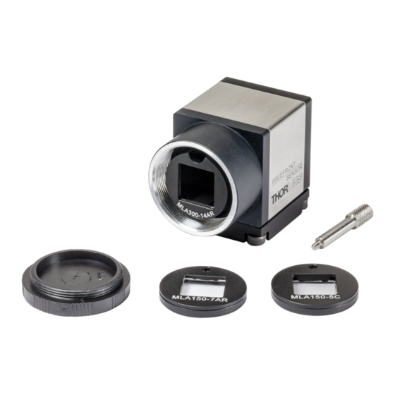
7.3 Exchanging the Microlens Arrays Up to three exchangeable microlens arrays (MLAs) (see WFS Products and Accessories are included with each Thorlabs Wavefront Sensor. The aperture of each MLA is customized for either the WFS20, WFS30, or WFS40. See chapter Parts List for details. -
Page 91: Hot Pixel
New hot pixel, visible in Lineview panel at horizontal position 200 As a part of the factory calibration, Thorlabs identifies and implements embedded hot pixel cor- rection for the Wavefront Sensors. After a long period of time and many temperature cycles,... - Page 92 Although the impact of single pixel defects to the WFS accuracy is negligible, the auto- matic exposure control may be influenced. If a new, stable and strong hot pixel (more than 50 digits intensity deviation from ambient pixels) appears, please return your WFS to Thorlabs for a factory hot pixel compensation. Please contact Thorlabs for return instructions.
-
Page 93: Appendix
Certifications and Compliances · Warranty · Copyright and Exclusion of Reliability · List of Acronyms · Literature · Certifications and Compliances · Warranty · Copyright and Exclusion of Reliability · Thorlabs Worldwide Contacts and 'End-of-Life' policy © 2007 - 2018 Thorlabs... -
Page 94: Technical Data
Software Selectable; H -> L or L -> H Safe Input Voltage Range -0.5 to 6.5 V Maximum LOW Level 1.5 V Minimum HIGH Level 3.5 V Input Impedance > 100 k Min. Pulse Width 10 µs Min. Slew Rate 5 V/ns © 2007 - 2018 Thorlabs... - Page 95 ) For longer exposure times, the min. trigger delay is increased by a further amount of (exposure time – exposure time limit) All technical data are valid at 23 ± 5°C and 45 ± 15% rel. humidity (non condensing) MLA Microlens Arrays for detailed specifications of the supplied mounted Microlens Ar- rays. © 2007 - 2018 Thorlabs...
- Page 96 Wavefront Sensor Selectable camera image sizes for WFS20 Image Sizes WFS20x (Normal Mode) Image Sizes WFS20x (bin2 Mode) © 2007 - 2018 Thorlabs...
- Page 97 47 x 35 1645 1080 x 1080 35 x 35 1225 768 x 768 23 x 23 512 x 512 15 x 15 360 x 360 11 x 11 WFS20-5C and WFS20-7AR: Frame Rate vs. Spot Count © 2007 - 2018 Thorlabs...
- Page 98 3. Zernike Fit · 4th order Zernike fit (15 modes) 4. Miscellaneous · disable graphics and extra data calculation Disable the DataSocket interface, as this slows down the measurement speed dramatically! © 2007 - 2018 Thorlabs...
- Page 99 8 Appendix Typical Wavelength Response Typical Response of the WFS20 CMOS Camera © 2007 - 2018 Thorlabs...
-
Page 100: Wfs30
0 to 30 V DC LOW Level 0.0 V to 2.0 V HIGH Level 5.0 V to 24 V Input Current, max. < 10 mA Min Pulse Width 100 µs Min. Slew Rate 35 V / msec © 2007 - 2018 Thorlabs... - Page 101 ) Radius of wavefront curvature over single lenslet aperture ) non-condensing All technical data are valid at 23 ± 5°C and 45 ± 15% rel. humidity (non condensing) MLA Microlens Arrays for detailed specifications of the supplied mounted Microlens Ar- rays. © 2007 - 2018 Thorlabs...
- Page 102 2 x 2 = 4 pixels only a single pixel is analyzed. The downside of the increased measurement speed is a decrease of measurement accuracy and spatial wavefront resolution. © 2007 - 2018 Thorlabs...
- Page 103 256 x 256 (sub2) 3.00 x 3.00 19 x 19 9 x 9 180 x 180 (sub2) 2.11 x 2.11 13 x 13 5 x 5 Typical Wavelength Response Typical Wavelength Response of the WFS30 CMOS Camera © 2007 - 2018 Thorlabs...
-
Page 104: Wfs40
0 to 30 V DC LOW Level 0.0 V to 2.0 V HIGH Level 5.0 V to 24 V Input Current, max. 10 mA Min Pulse Width 100 µs Min. Slew Rate 35 V / msec © 2007 - 2018 Thorlabs... - Page 105 ) Typical relative accuracy. Achievable after, and with respect to a user calibration, 10 image averages ) Over entire aperture of wavefront sensor ) Radius of wavefront curvature over single lenslet aperture ) non-condensing MLA Microlens Arrays for detailed specifications of the supplied mounted Microlens Ar- rays. © 2007 - 2018 Thorlabs...
- Page 106 Wavefront Sensor Selectable camera image sizes for WFS40 - Normal Mode © 2007 - 2018 Thorlabs...
- Page 107 8 Appendix Selectable camera image sizes for WFS40 - "sub2" Mode © 2007 - 2018 Thorlabs...
- Page 108 256 x 256 (sub2) 2.82 x 2.82 17 x 17 7 x 7 180 x 180 (sub2) 1.98 x 1.98 11 x 11 5 x 5 Typical Wavelength Response Typical Wavelength Response of the WFS40 CMOS Camera © 2007 - 2018 Thorlabs...
-
Page 109: Mla Microlens Arrays
4.1 mm 5.2 mm 14.6 mm Info value, not specified Nominal value, ±3% tolerance, Note: when built into a WFS, the effective focal length may differ! Effective (optimal) focal length when built into a WFS © 2007 - 2018 Thorlabs... - Page 110 The guaranteed reflectivity of the coating in the wavelength range 400 to 900 nm is below 1%. Reflectivity Reflectivity of MLA150-7AR and MLA300-14AR (including AR - Coating) Note © 2007 - 2018 Thorlabs...
-
Page 111: Minimal Beam And Pupil Diameter
Consequently, this minimum number of spots requires a beam and pupil diameter of at least a certain minimum size. The following graph shows the dependency for both available microlens arrays of 150 and 300 µm pitch. Minimum Beam and Pupil Diameter © 2007 - 2018 Thorlabs... -
Page 112: Trigger Input Wfs20
Attention Please see the External Trigger Input specifications for the allowed voltage level in order to avoid damage! Apply the external trigger signal using the trigger cable CAB-WFS20-T1 (available seperately) as shown below: © 2007 - 2018 Thorlabs... -
Page 113: Trigger Input Wfs30 And Wfs40
WFS30 and WFS40 are based. Attention Please see the External Trigger Input specifications for the allowed voltage level in order to avoid damage! Apply the external trigger signal using the trigger cable CAB-DCU-T3 as shown in the following sketch: © 2007 - 2018 Thorlabs... - Page 114 GPIO 1 blue Trigger IN (-) brown Flash OUT (+) yellow GPIO 2 Hirose HR25-7TR-8PA(73) Trigger IN (+) white male socket, camera rear view VCC OUT pink This cable can be ordered from Thorlabs (https://www.thorlabs.com/thorproduct.cfm?partnum- ber=CAB-DCU-T3). © 2007 - 2018 Thorlabs...
-
Page 115: Zernike Fit And Zernike Modes
. Generally a least square Zernike fit is done in order to determine the Zernike coefficients c A variety of definitions exist for these Zernike functions. The Thorlabs Wavefront Sensor soft- ware and this manual follows the ANSI Standard Z80.28-210, see... - Page 116 - 4xy Sec. Astig. Y y + 8xy - 6xy Spher. Aberr. 3 + 12x + 6y - 6x - 6y Sec. Astig. X - 4y - 3x + 3y Tetrafoil X - 6x © 2007 - 2018 Thorlabs...
- Page 117 Coma Y Z 10 TreX Trefoil X Z 11 TetY Tetrafoil Y Z 12 SAstY Secondary Astigmatism Y Z 13 SAb3 3rd Order Spherical Abberation Z 14 SAstX Secondary Astigmatism X Z 15 TetX Tetrafoil X © 2007 - 2018 Thorlabs...
-
Page 118: Example Zernike Calculations
= 3 mm? A2: To convert the PV value into a RoC result, a standard mathematimatical circle function is used. In literature [2] under ‘Sagitta’ the following formula is given: © 2007 - 2018 Thorlabs... - Page 119 Since the second term PV/2 is much smaller than the RoC to be calculated, this term can be omitted: The remaining formula gives an RoC of (3 mm) / (8 * 3.46 * 10 mm) = 325 mm. © 2007 - 2018 Thorlabs...
-
Page 120: Data Flow Chart
The following chart shows the data flow within the Wavefront Sensor software and the user defined inputs and data outputs. The brightness of the camera image is loop-controlled to ensure an optimal saturation level. The beam diameter and position are detected and are optionally used to define the instruments © 2007 - 2018 Thorlabs... -
Page 121: Troubleshooting
WFS through the software, try de- and reinstalling the software. If this problem cann ot be solved, please take screen shots of the error message and contact Thorlabs . We will be happy to help you. © 2007 - 2018 Thorlabs... -
Page 122: Drawings
MLA. Model Reference Plane - Distance "x" WFS20-5C 13.4 mm WFS20-7AR 12.2 mm WFS20-14AR 2.8 mm WFS30-5C 13.7 mm WFS30-7AR 12.6 mm WFS30-14AR 3.3 mm WFS40-5C 14.2 mm WFS40-7AR 13.1 mm WFS40-14AR 4.3 mm © 2007 - 2018 Thorlabs... -
Page 123: Drawing Wfs20-5C
8 Appendix 8.9.2 Drawing WFS20-5C © 2007 - 2018 Thorlabs... -
Page 124: Drawing Wfs20-5C/M
Wavefront Sensor 8.9.3 Drawing WFS20-5C/M © 2007 - 2018 Thorlabs... -
Page 125: Drawing Wfs20-7Ar
8 Appendix 8.9.4 Drawing WFS20-7AR © 2007 - 2018 Thorlabs... -
Page 126: Drawing Wfs20-7Ar/M
Wavefront Sensor 8.9.5 Drawing WFS20-7AR/M © 2007 - 2018 Thorlabs... -
Page 127: Drawing Wfs20-14Ar
8 Appendix 8.9.6 Drawing WFS20-14AR © 2007 - 2018 Thorlabs... -
Page 128: Drawing Wfs20-14Ar/M
Wavefront Sensor 8.9.7 Drawing WFS20-14AR/M © 2007 - 2018 Thorlabs... -
Page 129: Drawing Wfs20 Control Box
8 Appendix 8.9.8 Drawing WFS20 Control Box © 2007 - 2018 Thorlabs... -
Page 130: Drawing Wfs30-5C
Wavefront Sensor 8.9.9 Drawing WFS30-5C © 2007 - 2018 Thorlabs... -
Page 131: Drawing Wfs30-5C/M
8 Appendix 8.9.10 Drawing WFS30-5C/M © 2007 - 2018 Thorlabs... -
Page 132: Drawing Wfs30-7Ar
Wavefront Sensor 8.9.11 Drawing WFS30-7AR © 2007 - 2018 Thorlabs... -
Page 133: Drawing Wfs30-7Ar/M
8 Appendix 8.9.12 Drawing WFS30-7AR/M © 2007 - 2018 Thorlabs... -
Page 134: Drawing Wfs30-14Ar
Wavefront Sensor 8.9.13 Drawing WFS30-14AR © 2007 - 2018 Thorlabs... -
Page 135: Drawing Wfs30-14Ar/M
8 Appendix 8.9.14 Drawing WFS30-14AR/M © 2007 - 2018 Thorlabs... -
Page 136: Drawing Wfs40-5C
Wavefront Sensor 8.9.15 Drawing WFS40-5C © 2007 - 2018 Thorlabs... -
Page 137: Drawing Wfs40-5C/M
8 Appendix 8.9.16 Drawing WFS40-5C/M © 2007 - 2018 Thorlabs... -
Page 138: Drawing Wfs40-7Ar
Wavefront Sensor 8.9.17 Drawing WFS40-7AR © 2007 - 2018 Thorlabs... -
Page 139: Drawing Wfs40-7Ar/M
8 Appendix 8.9.18 Drawing WFS40-7AR/M © 2007 - 2018 Thorlabs... -
Page 140: Drawing Wfs40-14Ar
Wavefront Sensor 8.9.19 Drawing WFS40-14AR © 2007 - 2018 Thorlabs... -
Page 141: Drawing Wfs40-14Ar/M
8 Appendix 8.9.20 Drawing WFS40-14AR/M © 2007 - 2018 Thorlabs... -
Page 142: Safety
If necessary, ask for replacement packaging. Refer servicing to qualified personnel! Only with written consent from Thorlabs may changes to single components be made or com- ponents not supplied by Thorlabs be used. The instrument must only be operated with a duly shielded and low resistance USB cable de- livered by Thorlabs. - Page 143 Consult the dealer or an experienced radio/T.V. technician for help. Users that change or modify the product described in this manual in a way not expressly ap- proved by Thorlabs (party responsible for compliance) could void the user’s authority to operate the equipment.
-
Page 144: Certifications And Compliances
Wavefront Sensor 8.11 Certifications and Compliances © 2007 - 2018 Thorlabs... - Page 145 8 Appendix © 2007 - 2018 Thorlabs...
-
Page 146: Warranty
For warranty repairs or service the unit must be sent back to Thorlabs. The customer will carry the shipping costs to Thorlabs, in case of warranty repairs Thorlabs will carry the shipping costs back to the customer. -
Page 147: Copyright And Exclusion Of Reliability
8 Appendix 8.13 Copyright and Exclusion of Reliability Thorlabs has taken every possible care in preparing this document. We however assume no li- ability for the content, completeness or quality of the information contained therein. The content of this document is regularly updated and adapted to reflect the current status of the hardware and/or software. -
Page 148: List Of Acronyms
Universal Serial Bus Wavefront Sensor 8.15 Literature [1] ANSI Z80.28-2010 Ophthalmics - Methods of Reporting Optical Aberrations of Eyes: ANSI eStandards [2] Wikipedia - Circle: http://en.wikipedia.org/wiki/Circle (Creative Commons Attribution - ShareAlike 3.0 Unported [CC BY-SA 3.0]) © 2007 - 2018 Thorlabs... -
Page 149: Thorlabs Worldwide Contacts And Weee Policy
Contact Thorlabs for more information. Waste treat- ment is your own responsibility. “End of life” units must be returned to Thorlabs or handed to a company specializing in waste recovery. Do not dispose of the unit in a litter bin or at a public waste disposal site. - Page 150 Highest order in Fourier and DataSocket 41, 76, 80 Optometric calculations DataSocket Configuration Highspeed Mode DataSocket server Hot Pixel DataSocket Server Configuration Default 3D View Image Averages Default Setup Parameters Internal reference Default Top View Difference © 2007 - 2018 Thorlabs...
- Page 151 Zernike orders Omit Piston + Tip + Tilt Specifications of the Optical Abberations MLA150 Series Optometric constants 44, 72 spherical wavefront Spotfield Configuration Spotfield Panel Peak to Valley Pickup-Tool plane wavefront 46, 72 TCP/IP network © 2007 - 2018 Thorlabs...
- Page 152 Wavefront Sensor Setup Panel Wavefront Unit Wavelength waves WFS kits WFS Receiver WFS_Receiver example program wRMS Zernike Bar Graph Configuration Zernike Coefficients Panel Zernike Fit 38, 113 48, 113 Zernike Modes Zernike Order Zernike Polynomial, Cartesian © 2007 - 2018 Thorlabs...
- Page 153 www.thorlabs.com...
Need help?
Do you have a question about the WFS20-5CM and is the answer not in the manual?
Questions and answers