Cirris 4200 User Manual
Hide thumbs
Also See for 4200:
- Getting started manual (8 pages) ,
- Quick start manual (8 pages) ,
- Getting started manual (13 pages)
Table of Contents
Advertisement
Quick Links
Advertisement
Table of Contents

Related Manuals for Cirris 4200


Summary of Contents for Cirris 4200
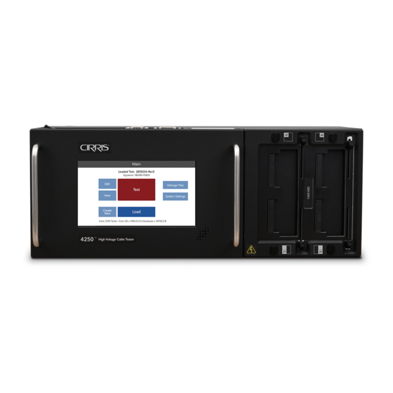
- Page 1 Cirris 4200 Series User Manual for 4200 & 4250 Testers...
-
Page 2: Table Of Contents
16.1.2 High Voltage Test – 4250 only ... . 34 5. Cirris Hub Software ......13 16.1.3 Intermittents Test . - Page 3 22.2 Wi-Fi ........44 22.2.1 Connecting to Cirris Hub....44 23.
-
Page 4: Safety/Support
Please make the following safety information available to any person who comes in contact with Cirris equipment. Cirris Systems will not be held liable for injuries suffered if the tester is not properly maintained or safety guidelines are not followed. -
Page 5: Warning Signs
User Precautions 1.3.5 To help ensure safety during testing, Cirris offers different tools such as switches, mats, and light curtains that can help create a safe testing environment. These tools are not necessary, but are recommended to ensure safety during testing. -
Page 6: Testing Basics
Types of Tests The 4200 Series allows you to customize which tests you want to run on a cable. While the tester will always perform a low voltage test, you can choose to include a high voltage or intermittents test. -
Page 7: Types Of Errors
2.2. Each of the tests performed by a Cirris tester will look for certain errors in the cable. Understanding the errors will help you determine which tests you want to run as well as how to avoid creating these errors in your cable. -
Page 8: Hardware Setup
3. Hardware Setup You should have received ● Cirris 4200 Low Voltage or 4250 High Voltage Cable Tester ● Power cord ● PC (USB A to USB B) cable ● Probe ● Antenna ● USB flash drive containing software/documentation ● Optional: Adapters, expansion boxes, tilt stands, and other accessories. -
Page 9: Top Of Tester
Top of Tester 3.3. a. Digital I/O: Build automation into your test process. b. Serial ports: Connect a PC and label printer directly to your tester. c. Probe: Attach the probe for troublshooting and diagnosing failures. d. PC (USB): Connect your tester to a computer to access test programs and other information. e. -
Page 10: Install Expansion Boxes
5. Connect the ribbon cable connector from the expansion box to the main unit and push the two units together. Note: Small posts on the expansion box will fit into corresponding holes in the main unit. Cirris 4200 Series User Manual... - Page 11 If you are attaching more than one expansion box, repeat the procedure. If your system uses all seven expansion boxes, you will need to purchase a second cable. Contact your account manager at Cirris for more information and to purchase this cable.
-
Page 12: Installing Adapters/Fixturing
Installing Adapters The 420 Series uses interchangeable adapters that connect the DUT to the tester. Cirris sells a variety of adapters that mate to standard connectors. We can also create custom adapters for less common connectors. Visit cirris.com to learn more. -
Page 13: Cirris Hub Software
5. Cirris Hub Software Before continuing with the tester setup, it is recommended that you install Cirris Hub Software onto a network PC. Cirris Hub Software allows you to do the following: ● File Sharing: Share test programs among networked testers. -
Page 14: Main Menu
Test System Settings ● Signature: Displays the loaded test’s signature. Tests that View are imported from other Cirris testers will show the same signature as displayed on those testers. Create Load ● Edit: Change settings for a loaded test program. -
Page 15: Create A New Test Program
7. Create a New Test Program Create a New Test Program A test program must be created before testing a cable. This is done by attaching a known-good sample cable to the tester, adjusting the test settings, and performing a Learn. The tester will create a list of test instructions based on the specified settings and the sample cable. -
Page 16: Test Preferences
● ON: When this setting is enabled, the user must enter a Lot ID before the test window will open. ● OFF: No Lot ID is required before testing and won’t appear on reports. Cirris 4200 Series User Manual... - Page 17 ■ External Start Switch External Switch allows the tester’s digital I/O port to receive an input signal from an external switch to start a test. Use Pin 1 on the digital I/O connector for the external start switch.The external switch can be a foot pedal or a button. ●...
-
Page 18: Low Voltage
● As shown in the graphic below, during a shorts test (checking for unintended connections), resistance measure- ments above the LV insulation resistance value will pass. Any connections detected below this value will be reported as a short error. Connection LV Insulation Resistance Resistance ∞ Good Shorts Cirris 4200 Series User Manual... - Page 19 ■ Component Resistance : (This value is only used when there are components in the test.) This value is auto-set during the Learn process, and should be 5-25% less than the lowest component found in the device being tested. ● Range: 0.1 ohm – 5.0 M ohm ●...
-
Page 20: High Voltage (Hipot) - 4250 Only
WARNING: Read the Safety/Support section of this manual (page 4) before performing high voltage testing. For more ideas on high voltage safety, visit cirris.com/safety. High Voltage Testing 10.1 High voltage settings can only be edited when high voltage is turned... -
Page 21: Advanced Settings
Advanced Settings 10.3 Advanced Settings Dielectric Withstand Test Dielectric Withstand (DW) Test Insulation Resistance (IR) Test 10.3.1 DW Voltage: IR Voltage: 300 V 300 V In a Dielectric Withstand (DW) Test, a voltage much higher than IR Minimum Resistance: DW Max Current: 0.1 mA 10 M ohm the normal operating voltage is applied between points on the... -
Page 22: Options
WARNING! High-Speed Mode with highly capacitive devices can slow testing. Highly capacitive nets may cause over- current failures, meaning the nets will need to be tested individually. This could cause the test to slow down significantly. Cirris 4200 Series User Manual... -
Page 23: Reports
11. Reports The 4200 Series testers can produce the following reports and labels: Run Report: Each line of the Run Report shows summary and statistical information for each DUT tested in a test run. This report Reports shows information on an entire test run, listing passes and failures. -
Page 24: Editing Report Templates
Reports Default report templates are provided by Cirris. If you would like to edit these reports, connect your tester to a PC. Navigate to the hidden reports file (see below) and make any necessary edits to the templates in a text editor. Save the template as a .prn file and replace the current template with the revised version. - Page 25 6. Load a test program and press Edit Test. Navigate to Reports and either add a new report or select a report to edit (page 31). 7. Under Change Template option, select the report template you added to the tester. Press OK to and save your changes. Note: To retrieve the original default template, delete the revised template.
-
Page 26: Digital I/O
DC +5 voltages through the switch circuit. Make sure you wire your external switch so it is normally open. Do not apply an AC voltage to the input. Example of Digital I/O input wired with start switch. Cirris 4200 Series User Manual... -
Page 27: Outputs
Outputs 12.2 The tester’s outputs are “sinking” (open collector) outputs. When activat- ed they will connect (or sink) to ground, in effect turning ON the output circuit. The outputs can sink up to a nominal 24 volts at 500 milliamps. To limit the output current, always ensure adequate resistance between power supply and the output. -
Page 28: Components (New Test Program)
Although tolerences that are automatically set during the Learn, review the test program to verify that the measured value of the components is the nominal vaue. One way to review the values is through a text editor such as in Cirris Hub Software. -
Page 29: Edit Data Collection Settings
The data is stored in the file [tester serial number].c_d and can be accessed through a text editor or SPC Link included in the SPC Data Collection software from Cirris. Use a USB cable, flash drive, or network cable to open the folder on a PC. -
Page 30: Perform A Learn
Perform a Learn 15.1 The 4200 Series tester creates test programs by scanning a cable and forming a list of instructions based on the cable and test settings. 1. From the Main Menu, press Learn New Test to reach the Create New Test screen. -
Page 31: Edit A Test Program
Components cannot be revised at this point on the tester. If you need to revise components, you can edit a test program using a text editor on a computer. One way to do this is using Cirris Hub Software (see page 13). -
Page 32: Edit Point Labels
J1-011 = Point_11 4. Save the file and close the program. 5. Turn on the tester. Load the edited test program. From the Main Menu press View to see the changes to the test program. Cirris 4200 Series User Manual... -
Page 33: Run A Test
16. Run a Test The tester performs three tests in the following order: ● Low Voltage Test: Tests for continuity and basic isolation. ● High Voltage Test – 4250 only: Tests for thorough isolation. ● Intermittents Test: Tests for intermittent errors that could arise while the cable is being moved. ■... -
Page 34: Low Voltage Test
Flex and move the cable while the tester continuously Abort checks continuity. If any failure is detected—even momentarily Low Voltage Test: Passed High Voltage Test: Passed — the test will fail. Lot: Passed: 0, Failed: 0 Total: 0 Print Done Cirris 4200 Series User Manual... -
Page 35: Finishing A Test
Finishing a Test 16.1.4 10. Upon completing the test(s), you may want a printed report Ready to Test Ready to Test summarizing the results. If auto-print was selected from the Test: NewTest Test: NewTest System Settings menu, a report will print automatically, or you Start Test Start Test Test: NewTest... -
Page 36: Interpreting Test Results
● This error could also be caused when the tester is charging the net or point given in the error message and the capacitance in the DUT is too high. A limit is in place to ensure safety while testing, so testing is immediately halted when the limit is reached. Cirris 4200 Series User Manual... - Page 37 Dielectric Failure Error: ● This error indicates that an arc occurred during the high voltage test to the net or point given in the error message. This error will occur anytime the current exceeds the ‘DW Max Current’ test setting. ●...
-
Page 38: Printing
18. Printing The 4200 Series can print full reports or labels. While a label printer can connect direcly to the tester, fullpage reports will need to be printed from a network printer. For information on customizing templates, see Reports on... -
Page 39: Manage Files
19. Manage Files All test programs, report templates, and other files can be accessed Manage Files through the Manage Files menu. From this menu, test programs can be organized, copied, and deleted. NewTest.wir New Folder Filter files: Use the drop-down list to filter files. The * symbol shows Delete all files. -
Page 40: Local Test Program Backup Via Usb Drive
WARNING! Do not format your drive. Formatting your drive will permanently erase all test programs and test settings. If this happens, you must contact Cirris to make your tester operational again. Local Test Program Backup via USB Drive 19.2 To back up test programs: 1. -
Page 41: System Settings
If the tester fails a self-test, a window will open with a description of the details of the failure. Note the details of the failure and contact Cirris Tech Support. -
Page 42: Legacy Defaults
If you change one test program, it has no effect on other test programs. To use test programs from a legacy tester, set the Legacy Defaults on your 4200 Series tester to match the system settings of your legacy Cirris tester. -
Page 43: Network Settings
22. Network Settings In order to print, the 4200 Series must be connected to a network running Cirris Hub Software. To set this up, from the Main Menu, select System Settings, and then Network Settings. The options on this screen will allow your tester to com- municate with a network running Cirris Hub Software. -
Page 44: Wi-Fi
● Port: You do not have to enter a port if the tester automatically detects the Cirris Hub Server on its subnet. The de- fault port is 12568 or enter the port number as set up by the IT administrator. -
Page 45: High Voltage Guidelines (4250 Only)
23. High Voltage Guidelines (4250 only) Use the following considerations to determine high voltage specifications: ● Customer needs, engineering necessities, or manufacturer’s specifications for wires and connectors. Note: Do not confuse the rated running voltage with a maximum hipot value. ●... - Page 46 ● A longer duration may be better for predicting some types of insulation failures and may increase the chance of detecting a breakdown condition. Cirris 4200 Series User Manual...
-
Page 47: Four-Wire Kelvin Testing
● The other senses voltage (referred to as “sense”) For the purpose of four-wire testing using the 4200 Series, test points are considered either Type 1 (T1) or Type 2 (T2) points. The tester uses T1 points as either force or sense; it uses T2 points as the compliment. Each four-wire pair from the tester must have one of each point. - Page 48 The location where the four-wire pair physically joins the test point connection of the device-under-test should be placed as close to the device-under-test as possible. The tester will measure any resistance from the fixturing exposed after the four-wire pair joins together. For more information on four-wire testing, visit cirris.com. Cirris 4200 Series User Manual...
-
Page 49: Calibration
If your tester fails the performance check, speak to your Cirris sales rep. Cirris or a third party lab can calibrate your tester. No external adjustments can be made to fix the tester’s calibration. -
Page 50: Connecting To Easy-Wire
26. Connecting to Easy-Wire™ You can operate your 4200 Series tester from a PC using Cirris Easy-Wire Software. Use the provided USB cable to connect your tester to a PC that is running Easy-Wire. Contact your sales representative for information on obtaining a software license. -
Page 51: Frequently Asked Questions
■ General Maintenance Do not open the tester chassis. Opening the chassis will void your warranty. The 4200 Series tester contains no internal user serviceable parts. Cleaning or routine maintenance of internal parts should be done at Cirris. Do not try to replace the lithium battery on the MCAN board. Should this battery, or any internal parts malfunction, contact Cirris for a repair. -
Page 52: Repair
Repair 27.3 Should your tester require repair, contact your Cirris representative for a free estimate. Depending on the extent of the dam- age, you may have to send your tester to Cirris headquarters. Cirris 4200 Series User Manual... -
Page 53: Factory Defaults
28. Factory Defaults The following table lists the settings for the 4200 Series testers and their corresponding factory defaults. Preferences Low Voltage Start Cable Attach High Voltage Start Start Button HV Auto Start Delay 1.0 S Intermittents Test For Duration... - Page 54 IR Minimum Resistance 50 M ohm IR Dwell Time 2 mS IR Soak Time Soak Until Good Components Settings Data Collection Data Collection Measured Values Error Text System Settings Volume Date MM_DD_YY Time Mains Frequency 60 Hz Cirris 4200 Series User Manual...
-
Page 55: Troubleshooting
If you suspect a problem with your tester unit, verify your tester is calibrated. You can purchase a verification kit from Cirris. If necessary, you may have to send the tester to Cirris for repair. ● High Voltage – 4250 only: To troubleshoot a high voltage failure such as a dielectric failure, remove the DUT and Learn a new test program with the same high voltage settings. -
Page 56: Glossary
Short: An unintended connection between 2 or more parts. This failure indicates insufficient insulation between metal conductors which were not intended to be connected. Test Program: The list of instructions used to test cables and harnesses. Cirris 4200 Series User Manual... -
Page 57: Specifications
31. Specifications ■ Test Points 128 points; expandable to 1024 points in 128-point increments ■ Low Voltage Test 2 Wire ● Voltage: 4 V max ● Current: 3 μA to 6 mA ● Resistance: 0.1 Ω to 100 k Ω ± 1% ± 0.1 Ω, 100k Ω to 5 MΩ ± 10% 4 Wire ●... - Page 58 ● File transfer: Transfer test programs either by connecting directly to a PC or using a USB flash drive. ● Printing: Local label printing via serial ports. Network printing via Cirris Hub™ Software. ● Optional PC control: Additional advanced features via Easy-Wire™ Software.
- Page 59 Specifications...
- Page 60 Cirris 4200 Series User Manual Version 2019.2.1 © 2018 Cirris Systems Corporation 401 North 5600 West Salt Lake City, Utah 84116 U.S.A. www.cirris.com...
Need help?
Do you have a question about the 4200 and is the answer not in the manual?
Questions and answers