
Related Manuals for Struck Magnatrac RS1000


Summary of Contents for Struck Magnatrac RS1000
- Page 1 RS1000 Operator Manual 1.01.19.qxp_Layout 1 4/24/19 12:41 PM Page 1 ® RS1000 Operator / Technical anual Struck Corp. - Cedarburg, WI 53012 Copyright 2019 C. F. Struck Corp. All rights reserved. Version 1.01.19...
-
Page 2: Very Important Facts & Tips For Performance
RS1000 Operator Manual 1.01.19.qxp_Layout 1 4/24/19 12:41 PM Page 2 Very Important Facts 2. It gives you maximum drawbar torque. & Tips for 3. It provides time to make “attachment ad- justments” on the go! Top Performance You’re encouraged to completely read this Man- ual to get a firm over-view of: how your RS100 op- erates, significant safety points, and also maintenance tips on how to increase your MAG-... - Page 3 Clutches are no different than the disk clutch found in a large truck...if you constantly slip the Clutch under heavy loads you will burn the clutch As always, the Struck Corporation through the faces and decrease clutch life. It’s no different customer service department, stands ready to with your Belt Clutches.
-
Page 4: Limited Warranty
In the event of defective materials or workmanship the purchaser agrees to allow C.F. Struck Corp the opportunity to cor- rect the defect in a timely manner at the expense of C.F. Struck Corp. It is at the discretion of C.F. Struck Corp to either correct the defect or refund the purchaser. -
Page 5: Table Of Contents
RS1000 Operator Manual 1.01.19.qxp_Layout 1 4/24/19 12:41 PM Page 5 TABLE OF CONTENTS VERY IMPORTANT FACTS & TIPS FOR PERFORMANCE ........2 1- TO THE OPERATOR . -
Page 6: 1- To The Operator
If in the future you need new parts to replace DANGER identifies the most serious hazards. those that may be worn, insist on genuine Struck parts. They are exact duplicates of the originals, Safety labels with the signal word DANGER or made from the same patterns and of the same WARNING are typically near specific hazards. -
Page 7: Service Records
RS1000 Operator Manual 1.01.19.qxp_Layout 1 4/24/19 12:41 PM Page 7 SERVICE & MAINTENANCE RECORDS Proper service and maintenance work is critical to trouble free operation of your equipment. It is also critical to diagnosing problems should they arise. Use the space provided on the following - page to record maintenance and service work performed. -
Page 8: 2- Safety Rules
RS1000 Operator Manual 1.01.19.qxp_Layout 1 4/24/19 12:41 PM Page 8 2- SAFETY RULES Carry the Bucket or Blade as low as possible at all times, especially when you work on a hillside Reports on accidents show that care- or back up a steep hill. less use of machinery causes a high percentage of accidents. -
Page 9: Service Safety
RS1000 Operator Manual 1.01.19.qxp_Layout 1 4/24/19 12:41 PM Page 9 SERVICE SAFETY cleaning parts. Use good commercial, nonflam- mable solvents. Be sure you understand a service procedure be- Provide adequate ventilation when charging bat- fore you work on the Crawler. tery. -
Page 10: Protection From Noise
RS1000 Operator Manual 1.01.19.qxp_Layout 1 4/24/19 12:41 PM Page 10 NOISE PROTECTION Prolonged exposure to loud noise can cause im- pairment or loss of hearing. Wear a suitable hear- ing protective device such as earmuffs or earplugs to protect against objectionable or uncomfortably loud noise. -
Page 11: 3- Controls And Instruments
RS1000 Operator Manual 1.01.19.qxp_Layout 1 4/24/19 12:41 PM Page 11 3- CONTROLS & INSTRUMENTS D - CHOKE CONTROL E - HEADLIGHT SWITCH Learn the location and purpose of all Controls, Instruments and Warning labels. Thoroughly F - KEY IGNITION SWITCH study the Operator’s Manual furnished by the en- gine manufacture and included with your Crawler instructions. -
Page 12: Left & Right Clutch Controls
RS1000 Operator Manual 1.01.19.qxp_Layout 1 4/24/19 12:41 PM Page 12 TURNING RIGHT: A & B - LEFT & RIGHT TRACK CLUTCH CONTROLS B - Right To turn sharply right, push forward on Left Track Control while holding Right Track Control in neu- A - Left tral. -
Page 13: Dashboard Controls
RS1000 Operator Manual 1.01.19.qxp_Layout 1 4/24/19 12:41 PM Page 13 DASHBOARD CONTROLS F - KEY IGNITION SWITCH Switch is activated by rotating key clockwise. C - THROTTLE CONTROL Turning it fully clockwise will engage engine starter The Throttle is lever operated, rotating in a wide ...release key and it will re- arc. - Page 14 RS1000 Operator Manual 1.01.19.qxp_Layout 1 4/24/19 12:41 PM Page 14 I - PARKING BRAKE HOUR METER / TACH FLASH ALERT: Flashes “CHG OIL” at 100 hour service The Parking Brake acts both as a parking brake intervals and “LUBE” at 25 hour service inter- vals, the service interval is based on actual run hours.
-
Page 15: 4- Operation
RS1000 Operator Manual 1.01.19.qxp_Layout 1 4/24/19 12:41 PM Page 15 4- OPERATION CAUTION - Before you start the engine: Clear the work area of people and obstacles PRE-STARTING INSPECTION Check the condition of the Crawler. (Prestart inspection). Before you start your Crawler for the first time each day, perform the following checks: Be sure there is enough ventilation. -
Page 16: Warm-Up Period
RS1000 Operator Manual 1.01.19.qxp_Layout 1 4/24/19 12:41 PM Page 16 TRAVELING CAUTION: Do not crank the Engine continuously for more than 10 seconds at a time. If the Engine does not start, allow a 60-second cool-down period be- I - Brake Handle tween starting attempts. -
Page 17: Parking & Storage
RS1000 Operator Manual 1.01.19.qxp_Layout 1 4/24/19 12:41 PM Page 17 PARKING THE CRAWLER Forward Forward 1. Lower all Attachments to the ground. Neutral Neutral 2. Allow Right and Left Track Controls to go “slowly” to neutral. 3. Engage Parking Brake. Reverse Reverse 4. -
Page 18: 5- Fuels And Lubricants
RS1000 Operator Manual 1.01.19.qxp_Layout 1 4/24/19 12:41 PM Page 18 5- FUELS LUBRICANTS & ENGINE OIL LUBRICANTS Check enclosed Engine Owner’s Manual and closely follow their recommendations. FUELS HYDRAULIC OIL (If equipped) FUEL SPECIFICATIONS Use a premium quality hydraulic oil with max- imum anti-wear properties, rust and oxidation Add fuel to fuel tank per engine manual specs. -
Page 19: 6- Lubrication And Periodic Service
RS1000 Operator Manual 1.01.19.qxp_Layout 1 4/24/19 12:41 PM Page 19 6- LUBRICATION EVERY TEN HOURS EVERY TEN HOURS & PERIODIC SERVICE Grease Fittings - Lubricate all grease fittings per location instructions in manual of each attachment you have mounted on your MAGNATRAC. - Page 20 Fuel Filter - Replace with new Fuel Filter at this Filters time: Filters can be purchased through the Replace Engine Air Filter with filter recom- Struck Corporation or through local engine mended in Engine Owner’s Manual. dealers. Tracks and Track Sprockets...
-
Page 21: 7- Service
RS1000 Operator Manual 1.01.19.qxp_Layout 1 4/24/19 12:41 PM Page 21 7- SERVICE gishly, check for the following: Run down battery. In the following Service section of this Manual, you Dirty, loose, or corroded cables and wires. will be required to do various assembly and dis- Engine oil viscosity too heavy. -
Page 22: Safety Interlock Switches
RS1000 Operator Manual 1.01.19.qxp_Layout 1 4/24/19 12:41 PM Page 22 COLD WEATHER BATTERY SERVICE Brake Lever Rod During cold weather, keep electrolyte in battery at #440 correct level (if applicable). Keep battery fully charged. Terminals BATTERY STORAGE #1148 #1674 If Crawler will be stored for more than 30 days, re- move battery. -
Page 23: Seat & Rear Cover Assembly
RS1000 Operator Manual 1.01.19.qxp_Layout 1 4/24/19 12:41 PM Page 23 SEAT & REAR COVER There are two methods to remove the Seat As- ASSEMBLY sembly. One is by removing the Assembly as a complete unit (It weighs about 45 lbs.). The sec- ond method takes longer but allows you to disas- #933A semble the unit into three components that weigh... - Page 24 RS1000 Operator Manual 1.01.19.qxp_Layout 1 4/24/19 12:41 PM Page 24 PARKING BRAKE SWITCH TEST provided into an “engaged” position, Parking Brake Switch should be “open” (the result of con- tact with the rotated #440 Leaf Spring). The light of #1625 the continuity tester should be Off! #933A DISENGAGED...
-
Page 25: Rear Drive Chain Tensioning
RS1000 Operator Manual 1.01.19.qxp_Layout 1 4/24/19 12:41 PM Page 25 REAR DRIVE CHAIN TENSIONING From “outside” the Crawler’s body, loosen (but do not remove) the five nuts on each (Left & Right) The #1805 Rear Drive Chains (#50 Roller Chain) #1611 Front Axle Plate. -
Page 26: Parking/Emergency Brake Adjustment
RS1000 Operator Manual 1.01.19.qxp_Layout 1 4/24/19 12:41 PM Page 26 Assembly (left side & right of body) a full revolution Begin your procedure by parking your Crawler on after each 1/4 turn of its respective Locknut. This an open, firm, level surface. Shut off Engine, en- will determine if there is a slight “high spot”... -
Page 27: Track Clutch Belts (Removal & Install)
RS1000 Operator Manual 1.01.19.qxp_Layout 1 4/24/19 12:41 PM Page 27 TRACK CLUTCH BELTS Carriage Bolt The following segment is divided into three sec- tions: 1) Belt Removal. 2) Belt Installation. Brake Lever firmly touching 3) Belt Adjustment. underside of Carriage Bolt It’s suggested that you read all three sections that follow to gain an overview before you begin any Tighten each of these Brake Assemblies by hold-... - Page 28 RS1000 Operator Manual 1.01.19.qxp_Layout 1 4/24/19 12:41 PM Page 28 CREATING BELT SLOT Remove the 3/8” nut securing each #1629 Belt Release. Remove both Belt Releases. The following steps cover the moving of the #252B Bearing (located on the top center inside Wall of Crawler) “inwardly”...
- Page 29 RS1000 Operator Manual 1.01.19.qxp_Layout 1 4/24/19 12:41 PM Page 29...
- Page 30 RS1000 Operator Manual 1.01.19.qxp_Layout 1 4/24/19 12:41 PM Page 30...
- Page 31 RS1000 Operator Manual 1.01.19.qxp_Layout 1 4/24/19 12:41 PM Page 31 At this time you can move to your left, the Belts through the “slot” you created on the “end” of the you wish to remove from the system. Slip them appropriate #1627 Upper and #1643 Lower Power through their respective “slot”...
- Page 32 RS1000 Operator Manual 1.01.19.qxp_Layout 1 4/24/19 12:41 PM Page 32 ter”. (Use this procedure for both the Upper & #2, #5, and #6 should be resting on “top” of their Lower Power Shafts). When you are done the respective #2051 Flat Idler Pulleys. Belts #3 and bearing end of shaft should look like photo (previ- #4 should rest “below”...
- Page 33 RS1000 Operator Manual 1.01.19.qxp_Layout 1 4/24/19 12:41 PM Page 33 CLUTCH BELT ADJUSTMENT Your Track Clutch Belts are adjusted as two #1629 “matched sets” of three belts each. One matched set (Belts #1, #2 and #3) for the Right Track and the other matched set (Belts #6, #5 and #4) for the Left Track.
- Page 34 RS1000 Operator Manual 1.01.19.qxp_Layout 1 4/24/19 12:41 PM Page 34 Replace both #1629 Belt Releases and secure each with original Locknuts. NOTE: Assemble such that “Tab” on both Belt Releases is “forward” of their Locknuts!. Upper Rod #1629 Lower Rod Make sure Belt Release’s Lower and Upper Rods are always on the “outside”...
-
Page 35: Engine Drive Chain (If Equipped)
RS1000 Operator Manual 1.01.19.qxp_Layout 1 4/24/19 12:42 PM Page 35 ENGINE DRIVE CHAIN ADJUSTMENT CHAIN (if equipped) To loosen or tighten the Chain, loosen the Lock- nut securing the #1689 Idler Sprocket and slide #1625 the Idler Sprocket assembly forward for Chain loosening, and rearward for tightening. -
Page 36: Eninge Drive Micro V-Belt (If Equipped)
RS1000 Operator Manual 1.01.19.qxp_Layout 1 4/24/19 12:42 PM Page 36 ENGINE DRIVE correct amount of tension on your drive belt at all MICRO-V BELT (if equipped) times. No need to make any drive belt adjust- ments! #1625 MICRO-V BELT REMOVAL & REPLACEMENT #933A If your #4356 Micro-V Drive Belt is broken, you should just be able to pull it out easily from the en-... - Page 37 #1617C tube of the #1617R Right Control Handle #4345 Assembly. For this part of the install, (Please ref- erence pages 28-32 in Section 7). Speak with a Struck tech for additional help. There may be other ways to do this procedure. Around bottom Around bottom of #4341 &...
- Page 38 RS1000 Operator Manual 1.01.19.qxp_Layout 1 4/24/19 12:42 PM Page 38 #1521 #4341 #4341 #1521 Loose #4356 #1521 Locknut #4356 #4344 #4344 10. At this time double check your work. Take a look at the #4356 Micro-V belt to make sure it is aligned and seated properly, and also that any loosend set screws have had red-loctite added to them and fully tightened.
-
Page 39: Steel Track Removal (If Equipped)
RS1000 Operator Manual 1.01.19.qxp_Layout 1 4/24/19 12:42 PM Page 39 STEEL TRACK MAINTENANCE STEEL TRACK REMOVAL (if equipped) From below, support body of Crawler so its Tracks clear the ground by approximately 2” and are free Before attempting to complete any part of this to rotate...release Brake at this time. - Page 40 RS1000 Operator Manual 1.01.19.qxp_Layout 1 4/24/19 12:42 PM Page 40 4. As the Track is rotated forward, work the forward 3. The Track’s Inner Chain should now be located end of the Track outward. Stop working the Track between the Inner & Outer Sprockets of the Front outward when the Track’s Inner Chain is centered Idler and Rear Drive.
-
Page 41: Steel Track Tensioning (If Equipped)
RS1000 Operator Manual 1.01.19.qxp_Layout 1 4/24/19 12:42 PM Page 41 STEEL TRACK TENSIONING NOTE: This is a simple adjustment, but it’s proper execution results in extremely stable Track performance in the future! 1. Over protruding “threaded end” of each #1810 Tension Bolt (on each side of Crawler body) slip 4. - Page 42 RS1000 Operator Manual 1.01.19.qxp_Layout 1 4/24/19 12:42 PM Page 42 MAINTENANCE STEEL TRACK TENSIONING NOTE: This is a simple adjustment, but it’s proper execution results in extremely stable Track performance in the future! Begin by checking the overall length of the #1806 Spring on each side of Crawler.
-
Page 43: Rubber Track Removal (If Equipped)
RS1000 Operator Manual 1.01.19.qxp_Layout 1 4/24/19 12:42 PM Page 43 RUBBER TRACK MAINTENANCE RUBBER TRACK REMOVAL (if equipped) From below, support body of Crawler so the Tracks clear the ground by approximately 2” and Before attempting to complete any part of this are free to rotate...release Brake at this time. - Page 44 RS1000 Operator Manual 1.01.19.qxp_Layout 1 4/24/19 12:42 PM Page 44 (4) Nuts #1611 (1) Nut #2065 Front Idler Sprocket Pound Rearward Once the track is removed, your crawler track sys- tem should now look like the following picture. HINT: With a mallet, gently pound rearward on the Note: Center idlers not shown for clarity.
-
Page 45: Rubber Track Tensioning (If Equipped)
“seated” into the track openings. If you Pound Forward have questions please call the factory and ask to speak with a struck technician regarding any ad- ditional questions or concerns that you may have. Once happy with the track “seating”, please repeat these steps for the other side of the crawler. - Page 46 RS1000 Operator Manual 1.01.19.qxp_Layout 1 4/24/19 12:43 PM Page 46 3. Work back and forth from left side to right side, pander plate. Re-adjust if necessary. 1/4” at a time, until 1/2” of space is between the “front edge” of the #2065 Axle and the “rear 7.
- Page 47 RS1000 Operator Manual 1.01.19.qxp_Layout 1 4/24/19 12:43 PM Page 47 MAINTENANCE RUBBER TRACK TENSIONING Begin by checking that 1/2” of space is between #1611 the “front edge” of the #2065 Axle and the “rear edge” of the expander plate. Front Idler Sprocket #2065...
-
Page 48: 8- Trouble Shooting
RS1000 Operator Manual 1.01.19.qxp_Layout 1 4/24/19 12:43 PM Page 48 SWITCHING OUT cating your blocking, analyze the total weight and STEEL TRACK SYSTEM TO balance of the Crawler as it will change as the Tracks are removed and then replaced! RUBBER TRACK SYSTEM NOTE: As you work with the Tracks, realize that the more you can support the “lower strand”... - Page 49 RS1000 Operator Manual 1.01.19.qxp_Layout 1 4/24/19 12:43 PM Page 49 5. As the Track is rotated forward, work the for- 1. Remove the remaining locknuts from the left ward end of the Track outward. Stop working the and right tension bolts. Your front tension bolt as- Track outward when the Track’s Inner Chain is sembly should be loose.
- Page 50 RS1000 Operator Manual 1.01.19.qxp_Layout 1 4/24/19 12:43 PM Page 50 #1805 #1805 2065 Axles #1650 Locknuts 6. Push Rear Axle forward evenly, turn one Lock- nut 1/4 turn, then go to the other side and loosen 3. Remove both front and rear snap rings on the other Locknut 1/4 turn...use this back and forth procedure until both #1805 Rear Drive Chains the (2) #2065 Axles, by inserting a small flat...
- Page 51 RS1000 Operator Manual 1.01.19.qxp_Layout 1 4/24/19 12:43 PM Page 51 At this time, your #2065 axles should be RIGHT BODY WALL potruding from the outside of the machine as shown in the picture below. ADJUSTMENT SLOT 1” 4. Using your new Front Axle Bracket as a template, insert (3) of your 5/16” Carriage #2065 Bolts through the new axle bracket and the...
- Page 52 RS1000 Operator Manual 1.01.19.qxp_Layout 1 4/24/19 12:43 PM Page 52 RUBBER TRACK SPROCKET ASSEMBLY NOTE: In the photos that follow, the #4349 4350 Rubber Track front idlers and #4350 Rubber Track rear drive sprockets will look different Rear Drive from what is shown, but the assembly process Sprocket will be the same.
- Page 53 RS1000 Operator Manual 1.01.19.qxp_Layout 1 4/24/19 12:43 PM Page 53 1691 Expander 1/2” Bolt 1/2” Flat- Washer 1/2” Nut 2065 Front & Rear Axles 1691 Expander 9. Secure Axles by sliping a #727 Snap Ring 12. Insert #1810 Track Tension Bolt into over each Axle end and engage it into the square hole in end of #1691 Expander as- groove provided in each Axle.
- Page 54 RS1000 Operator Manual 1.01.19.qxp_Layout 1 4/24/19 12:43 PM Page 54 REAR DRIVE CHAIN NOTE: When installed, the pins of each Link AND CHAIN GUARD ASSEMBLY should point to the center of your Magnatrac... see Photo at the bottom of previous column. The following bolded text should have been 3.
- Page 55 RS1000 Operator Manual 1.01.19.qxp_Layout 1 4/24/19 12:43 PM Page 55 5. Closely following the Photo at the bottom 2. Install (3) #706 O-rings into each side of the right of the previous page, insert three (3) #U #4351 Idler. The O-rings should rest against Bolts into outside face of each #1636 Chain the inside brass bushing.
- Page 56 RS1000 Operator Manual 1.01.19.qxp_Layout 1 4/24/19 12:43 PM Page 56 5. Secure #4354 Center Axles with (1) 5/16”- wall. Attach a 5/16” Nut to the inside of the 18 x 1 1/4” Spin Lock Bolt and (1) 5/16”-18 body wall. See picture below. Spin Lock Nut...tighten.
- Page 57 RS1000 Operator Manual 1.01.19.qxp_Layout 1 4/24/19 12:43 PM Page 57 when dropping them in. See picture below. (2) Shims Shim Idler Frame (2) Shims Assembly Track Expander 13. Drop in from above, additional #4353 Shims on both sides, to allow approx. equal spacing between track sprocket path an idler wheel path.
- Page 58 RS1000 Operator Manual 1.01.19.qxp_Layout 1 4/24/19 12:43 PM Page 58 8- TROUBLESHOOTING the tractor and/or attachments while not properly located in the operator’s seat. • If the engine dies continuously, check the Below are tips and guidelines for trou- wire connections and verify wires are not bleshooting some problems or concerns, which frayed or damaged.
- Page 59 RS1000 Operator Manual 1.01.19.qxp_Layout 1 4/24/19 12:43 PM Page 59 MAGNATRAC has little power. Tracks came off. • Verify engine throttle is adequate; check the • Do NOT proceed operating the MAGNA throttle connections. TRAC. Lower all attachments and apply the parking brake.
-
Page 60: 9- Safety & Work Procedures
RS1000 Operator Manual 1.01.19.qxp_Layout 1 4/24/19 12:43 PM Page 60 9- SAFETY & WORK PROCEDURES for MAGNATRACS The following material is designed to familiarize you with the basic characteristics of a MAGNATRAC (tracked Vehicle). Its purpose is to teach you how a MAGNATRAC responds in comparison to the more familiar wheeled tractors. - Page 61 RS1000 Operator Manual 1.01.19.qxp_Layout 1 4/24/19 12:43 PM Page 61 A tracked Vehicle, by its very nature, requires the use of operating techniques and procedures that are unfamil- SAFETY WARNING: ANYTIME A PORTION OF iar to most people used to driving wheeled vehicles. THE TRACK IS NOT IN CONTACT WITH THE GROUND, STABILITY IS REDUCED.
- Page 62 RS1000 Operator Manual 1.01.19.qxp_Layout 1 4/24/19 12:43 PM Page 62 TRACKED VEHICLE OPERATION cific obstacle can be traversed. If in doubt, do not at- tempt. A Tracked Vehicle, by its very nature, is a vehicle re- quiring a great degree of care and judgment during opera- tion.
- Page 63 RS1000 Operator Manual 1.01.19.qxp_Layout 1 4/24/19 12:43 PM Page 63 DOWNHILL OPERATION SAFETY WANING: OBSTACLES, SOME OF WHICH MIGHT BE DRIVEN OVER SAFELY SUDDEN STOPS WHILE ON LEVEL TERRAIN, CAN CAUSE A If a Tracked Vehicle is driven down a slope and the HAZARD WHILE OPERATING ON SLOPES.
- Page 64 RS1000 Operator Manual 1.01.19.qxp_Layout 1 4/24/19 12:43 PM Page 64 OPERATING SAFETY PRECAUTIONS variables are the steepness of the slopes, size of the ob- stacle causing the drop, the shape of the last point of sup- 1. Keep hands and feet inside vehicle. port, the load on the Tracked Vehicle, initial speed, 2.
-
Page 65: Loader Operation
RS1000 Operator Manual 1.01.19.qxp_Layout 1 4/24/19 12:43 PM Page 65 LOADER OPERATION With the bucket level, start a cut at the notch approxi- mately 2 inches (50.8 mm) deep. Hold the depth by feath- Suggested operating techniques for loader operation ering the bucket to adjust the cutting lip up or down. - Page 66 RS1000 Operator Manual 1.01.19.qxp_Layout 1 4/24/19 12:43 PM Page 66 OPERATING WITH FLOAT CONTROL (if equipped) DUMPING THE BUCKET During hard surface operation, place the control lever Lift the bucket high enough to clear the side of the ve- in “float” (held by the detent), and keep the bucket level. hicle.
- Page 67 RS1000 Operator Manual 1.01.19.qxp_Layout 1 4/24/19 12:43 PM Page 67 LOADING FROM A STOCKPILE Leave soil that drifts over the side of the bucket for final cleanup. Initially approach the stockpile with the bucket approx- One lengthwise cleanup pass will usually leave the imately 2 feet (609.6 mm) off of the ground.
-
Page 68: Misc. (Snowplowing, Logging, Etc.)
RS1000 Operator Manual 1.01.19.qxp_Layout 1 4/24/19 12:43 PM Page 68 Always keep the truck close to the operation and keep If the pile sides are too high and are likely to cave in, cutting depth half the length of the truck bed. use the loader to break them down. -
Page 69: Bulldozing
RS1000 Operator Manual 1.01.19.qxp_Layout 1 4/24/19 12:43 PM Page 69 BULLDOZING DOZER DITCHING A dozer and blade can dig wide, shallow ditches effec- tively as shown in the following illustrations. When the DOZER EXCAVATION limits for side excavation are reached (A)... When dozing out a pit with a blade or bucket, make cross cuts working from South to North in overlapping swaths. - Page 70 RS1000 Operator Manual 1.01.19.qxp_Layout 1 4/24/19 12:43 PM Page 70 SIDE HILL CUTS 2. Working from Side (only) Always start or pioneer all side hill cuts from the top of A short, wide shelf may also be cut in a hillside, work- hills and then work your way down with the cut.
-
Page 71: 10- Parts Listing & Diagrams
RS1000 Operator Manual 1.01.19.qxp_Layout 1 4/24/19 12:43 PM Page 71 EARTH MOVING BACKFILLING When stripping soil from a road or driveway, either Angling blade bulldozers are excellent for backfilling push it forward and angle it to the side (A) or push it for- ditches as they can drift material into the trench while ward, then perpendicularly push it to the side (B). - Page 72 RS1000 Operator Manual 1.01.19.qxp_Layout 1 4/24/19 12:43 PM Page 72 TECHNIQUES FOR COMPLETING VARIOUS PROP- Another method commonly used: Start at the bottom ERTY IMPROVEMENTS and travel diagonally up the slope. In this way a windrow will be continually drifted to one side and will tend to fill When enlarging ponds or streams, leave a ridge be- low spots or irregularities.
-
Page 73: Backhoe Operation
RS1000 Operator Manual 1.01.19.qxp_Layout 1 4/24/19 12:43 PM Page 73 BACKHOE OPERATION When lifting a full bucket, there is a tendency for the front of the tractor to rise. COunterweight in the form of a TERMINOLOGY ballast box is required to overcome this tendency. The backhoe should not exert more lift force than the effective BOOM counterweight can balance. - Page 74 RS1000 Operator Manual 1.01.19.qxp_Layout 1 4/24/19 12:43 PM Page 74 DUMPING THE BUCKET To dump the bucket at the end of the digging cycle, lift the bucket clear of the trench while crowding it out and swinging it to the spoil pile. As the pile is approached, dump the bucket.
- Page 75 RS1000 Operator Manual 1.01.19.qxp_Layout 1 4/24/19 12:43 PM Page 75 stabilizers as possible. Pile the spoil on the opposite side Level the backhoe on slopes with the stabilizers to dig of the trenches. plumb trenches, or... Continue the trench by moving the Tractor forward..use the backhoe or loader to cut a level slot for the uphill Moving too far will require excessive down pressure for track and stabilizer.
-
Page 76: Wiring Diagram
RS1000 Operator Manual 1.01.19.qxp_Layout 1 4/24/19 12:43 PM Page 76 CONTINUOUS TRENCHING WITH SPACED BELL- DIGGING STRAIGHT WALL SHALLOW BASEMENTS HOLES Begin at one corner, removing a much material as Begin by digging the trench to the desired grade. possible to grade level. Then, reset the unit forward and Progress along the trench to the bellhole locations and dig continue digging to grade. - Page 77 RS1000 Operator Manual 1.01.19.qxp_Layout 1 4/24/19 12:43 PM Page 77 PIPELINE LEAK REPAIR When grave markers prevent a straight-in position back the tractor in at a 45° or 90° angle to the grave site. Locate the pipeline with a bellhole about six feet (182 Position the tractor close enough to the grave to dig a cm) wide and tenn feet (304 cm) long.
- Page 78 RS1000 Operator Manual 1.01.19.qxp_Layout 1 4/24/19 12:43 PM Page 78 MISCELLANEOUS TREE REMOVAL Light trees and brush are removed by lowering the SNOW PLOWING blade a few inches into the ground just enough to strike Snow is bulkier than dirt and its slippery consistency and cut roots...usually done in first or second gear.
- Page 79 RS1000 Operator Manual 1.01.19.qxp_Layout 1 4/24/19 12:43 PM Page 79 to fall over, reverse tractor quickly, for the roots pulling out When the tree is too large to lift in a bucket, dig of the ground may damage the machine. Next fill stump around the tree (as previously described) and then push it hole and then lift entire root section clear of the ground.
- Page 80 RS1000 Operator Manual 1.01.19.qxp_Layout 1 4/24/19 12:43 PM Page 80 MOVING BOULDERS AND STONE Dozers can move large rocks on firm ground perhaps several times its own weight. If the stone is too large for direct pushing, it can be pushed first on one side and then on the other.
-
Page 81: Parts List
RS1000 Operator Manual 1.01.19.qxp_Layout 1 4/24/19 12:43 PM Page 81 10- PARTS LIST Item # Description 000069 Coated Clip 1 000228 Key, 1/4" x 1/4" x 1" Machine Key 000277 Grommet, 3/4" 000278 Grommet, 1" 000279 Grommet, Rubber 1 1/2" 000413 Battery Strap 1 000433 Clip, Coated 000440... - Page 82 RS1000 Operator Manual 1.01.19.qxp_Layout 1 4/24/19 12:43 PM Page 82 Item # Description 001792 Brake Yoke, painted 001802 Brake disc, 1 in. bore w/keyway 001804 40LL X-RIng Riveted Chain (100 pitches), (If Equipped) 001806 Track tensioner, plastic, 1 1/2in long x 3/4 in ID x 1 3/4 in OD. 001810 Track Tension Bolt, 1/2 x 13 x 8 in.
- Page 83 Shell (single pc), 3 3/4" OD 000252B Bearing with Collar & Set screws, 1" ID x 2" OD 000819A Paint, "2013 STRUCK Yellow" - 16 oz. aerosol spray can 001010C Washer/spacer, 1" OD X 5/16" ID X 1/8" Thick, painted 001600XX...
- Page 84 RS1000 Operator Manual 1.01.19.qxp_Layout 1 4/24/19 12:43 PM Page 84 Item # Description 001828XX #14 blue x 19 in. lng w/ 1 000293, 1 000299, 1 000284 001830XX Brown 20 in w/ 1 000296 and red 38 1/2 w 1 001853 001831XX #14 white x 16 lng w/ 1 0001853 and 1 001855 001835XX...
- Page 85 RS1000 Operator Manual 1.01.19.qxp_Layout 1 4/24/19 12:43 PM Page 85 Item # Description BOLT-5/16-16 5/16 - 18 X 5 G5 BOLT BOLT-5/16-201 5/16 x 3/4" HH Capscrew G5 Zinc BOLT-5/16-83 5/16-18X3/4 G5 CARR BLT ZC BOLT-5/16-9 5/16-18 X 1 3/4 G5 BOLT BOLT-8-18-190 8-18X 1/2 HX SELF TAPPER BOLT-8-32-195...
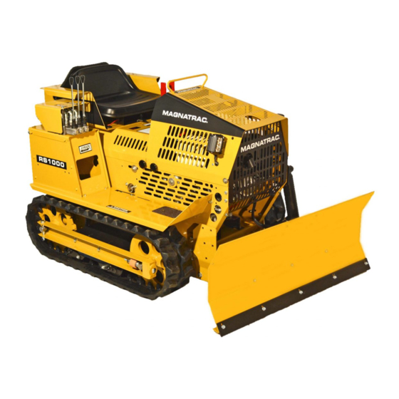
- Page 86 Magnatrac RS1000 Overview - Left View This section of your Magnatrac RS1000 Operator/Technical Manual is designed to help you quickly locate parts and assemblies you will need to identify to properly maintain and service your Magnatrac. The pho- tos are used to familiarize yourself with the MAGNATRAC.
- Page 87 RS1000 Operator Manual 1.01.19.qxp_Layout 1 4/24/19 12:43 PM Page 87 Photo RS-2 Magnatrac RS1000 Overview - Close Up Views Headlight Choke Throttle Switch Choke Handle Handle Connection Ignition Engine Safety Circuit Breaker Fuel Shut-Off Grease Points Adjustment Holes for Seat...
- Page 88 RS1000 Operator Manual 1.01.19.qxp_Layout 1 4/24/19 12:43 PM Page 88 WIRING DIAGRAM GX390 HONDA Engine with HONDA ELECTRIC Start - 2019 Headlight [4347] 1838 1838 Headlight Engine [4347] Fuse Holder Light Switch Solenoid [447] [284] Control Box Fuse [1234] 1828 Key Switch 1837 1831...
Need help?
Do you have a question about the Magnatrac RS1000 and is the answer not in the manual?
Questions and answers
What are the specifications for an original v belt for the Struck RS1000 mini dozer
The original V belt for the Struck Magnatrac RS1000 mini dozer is the #4356 Micro-V Belt. It is routed around the #1643/#4355 Lower Power Shaft, passes around the #4346 #1617C tube of the #1617R Right Control Handle #4345 Assembly, and is looped between the #4345 Micro-V Engine Pulley and the body wall. The belt should be properly seated and appear as shown in the manual's reference images.
This answer is automatically generated