Cypress PSoC CY8CPROTO-063-BLE Quick Start Manual
6 ble prototyping board
Hide thumbs
Also See for PSoC CY8CPROTO-063-BLE:
- Quick start manual (3 pages) ,
- Quick start manual (3 pages)

Related Manuals for Cypress PSoC CY8CPROTO-063-BLE


Summary of Contents for Cypress PSoC CY8CPROTO-063-BLE
- Page 1 CY8CPROTO-063-BLE ® PSoC 6 BLE Prototyping Board Guide Doc. # 002-24993 Rev. ** Cypress Semiconductor 198 Champion Court San Jose, CA 95134-1709 www.cypress.com...
- Page 2 Cypress is not liable, in whole or in part, and you shall and hereby do release Cypress from any claim, damage, or other liability arising from or related to all Unintended Uses of Cypress products.
-
Page 3: Table Of Contents
Contents Safety and Regulatory Compliance Information 1. Introduction Kit Contents .........................8 PSoC Creator ......................9 1.2.1 PSoC Creator Code Examples ..............10 1.2.2 PSoC Creator Help ..................11 1.2.3 Component Datasheets .................11 Getting Started......................12 Additional Learning Resources..................12 Technical Support......................13 Documentation Conventions..................13 Acronyms........................13 2. Software Installation Before You Begin.......................15 Install Software ......................15 Uninstall Software......................16... - Page 4 Contents A. Appendix Board Details ......................26 Hardware Details .......................28 A.2.1 Target Board ....................28 A.2.2 KitProg2 Board....................29 A.2.3 Power Supply System ..................30 A.2.4 Board Separation (Snapping).................31 A.2.5 Header Connections ..................32 A.2.6 PSoC 6 BLE Prototyping Board features ............36 Programming PSoC 6 BLE Prototyping Board using MiniProg3/KitProg2....40 Revision History PSoC®...
-
Page 5: Safety And Regulatory Compliance Information
Safety and Regulatory Compliance Information The CY8CPROTO-063-BLE PSoC 6 BLE Prototyping Board is intended for use as a development platform for hardware or software in a laboratory environment. The board is an open system design, which does not include a shielded enclosure. This may cause interference to other electrical or electronic devices in close proximity. - Page 6 General Safety Instructions ESD Protection ESD can damage boards and associated components. Cypress recommends that you perform procedures only at an ESD workstation. If such a workstation is not available, use appropriate ESD protection by wearing an anti-static wrist strap attached to the chassis ground (any unpainted metal surface) on your board when handling parts.
-
Page 7: Introduction
1.8 V to 3.3 V operation ■ The CY8CPROTO-063-BLE PSoC 6 BLE Prototyping Board also integrates Cypress KitProg2 that enables onboard programming, debugging, and bridging functionalities, such as USB-UART and USB-I2C. KitProg2 is used to program and debug the target PSoC 6 MCU which is part of the BLE... -
Page 8: Kit Contents
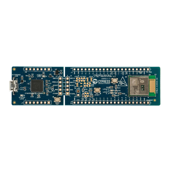
Introduction Kit Contents The CY8CPROTO-063-BLE PSoC 6 BLE Prototyping Kit contains PSoC 6 BLE Prototyping Board (which contains CYBLE-416045-02 EZ-BLE Creator Module), USB 2.0 Type-A to Micro-B Cable and Quick Start Guide. Figure 1-1. CY8CPROTO-063-BLE PSoC 6 Prototyping Board - Top View Figure 1-2. -
Page 9: Psoc Creator
Figure 1-3. PSoC Creator Features PSoC Creator also enables you to tap into an entire tool ecosystem with integrated compiler chains and programmers for PSoC devices. For more information, visit www.cypress.com/psoccreator. Visit the PSoC Creator Video Training Page for video tutorials on learning and using PSoC Creator. -
Page 10: Psoc Creator Code Examples
Introduction 1.2.1 PSoC Creator Code Examples PSoC Creator includes a large number of code examples. These examples are available from the PSoC Creator Start Page, as shown in Figure 1-4 or from the menu File > Code Example. Figure 1-4. Code Examples in PSoC Creator Code examples can speed up your design process by starting you off with a complete design, instead of a blank page. -
Page 11: Psoc Creator Help
Introduction 1.2.2 PSoC Creator Help Launch PSoC Creator and navigate to the following items: Quick Start Guide: Choose Help > Documentation > Quick Start Guide. This guide gives you ■ the basics for developing PSoC Creator projects. Simple Component Code Examples: Choose File > Code Example. These examples demon- ■... -
Page 12: Getting Started
MiniProg3, Kit Schematics, and the bill of materials (BOM). Additional Learning Resources Cypress provides a wealth of data at www.cypress.com to help you to select the right PSoC device for your design, and to help you to quickly and effectively integrate the device into your design. For a... -
Page 13: Technical Support
■ comprehensive list of video training on PSoC Creator. Learning from Peers: Visit community.cypress.com/welcome to meet enthusiastic PSoC ■ developers discussing the next-generation embedded systems on Cypress Developer Community Forums. Technical Support For assistance, visit Cypress Support. You can also use the following support resources if you need quick assistance: Self-help (Technical Documents). - Page 14 Introduction Table 1-2. Acronyms Used in this Document (continued) Acronym Definition GPIO General-Purpose Input/Output Inter-Integrated Circuit IDAC Current DAC Integrated Design Environment Internal Main Oscillator Knowledge Based Article Light-Emitting Diode Phase Locked Loop PSoC Programmable System-on-Chip Successive Approximation Register Serial Communication Block SRAM Serial Random Access Memory Serial Wire Debug...
-
Page 15: Software Installation
Before You Begin To install Cypress software, you will require administrator privileges. However, they are not required to run the software that is already installed. Before you install the kit software, close any other Cypress software that is currently running. -
Page 16: Uninstall Software
The software can be uninstalled using one of the following methods: 1. Go to Start > All Programs > Cypress > Cypress Update Manager and select Uninstall. 2. Go to Start > Control Panel > Programs and Features for Windows 7 or Add/Remove Programs for Windows XP and select Uninstall/Change. -
Page 17: Kit Operation
Prototyping Kit. This primarily includes the programming and debugging functionalities, KitProg2 USB-UART and USB-I2C bridges, and the procedure to update the KitProg2 firmware. Theory of Operation Figure 3-1. Block Diagram of CY8CPROTO-063-BLE PSoC 6 BLE Prototyping Board Cypress Part Loaded Parts No Load Parts KitProg2 Module Section... - Page 18 Note: The button connects the PSoC 6 MCU pin (P0[4]) to ground when pressed. Therefore, you need to configure the PSoC 6 MCU pin as ‘resistive pull-up’ for detecting the button press. EZ-BLE Module: The EZ-BLE Module (CYBLE-416045-02) from Cypress is used to ■...
-
Page 19: Programming And Debugging The Target Psoc 6 Mcu
Kit Operation Programming and Debugging the Target PSoC 6 MCU The target PSoC 6 MCU can be programmed and debugged using KitProg2. Before programming the device, make sure that PSoC Creator and PSoC Programmer software are installed on the PC. Install Software chapter on page 15 for more information. -
Page 20: Debugging Using Psoc Creator
Kit Operation 4. If there are no errors during build, program the firmware onto the kit by choosing Debug > Program or press Ctrl + F5, as shown in Figure 3-4. This programs the target PSoC 6 MCU on the Prototyping Board. Figure 3-4. -
Page 21: Usb-Uart Bridge
Kit Operation USB-UART Bridge KitProg2 on the PSoC 6 BLE Prototyping Board can act as a USB-UART bridge. The UART lines between KitProg2 and the target are hard-wired on the board, through the snappable area, with UART_RX assigned to P5[0] and UART_TX assigned to P5[1] on target PSoC 6 MCU. For more details on the KitProg2 USB-UART functionality, see the USB-UART Bridge section in the KitProg2 User... -
Page 22: Code Examples
Using Built-in PSoC Creator Code Examples with the Kit Follow these steps to open and use the built-in PSoC Creator examples. 1. Launch PSoC Creator from Start > All Programs > Cypress > PSoC Creator <version> > PSoC Creator <version>. - Page 23 Code Examples 3. In the Find Code Example window, set the Device family to PSoC 63 as shown in Figure 4-2. Figure 4-2. Selecting PSoC 63 Device in Find Code Example Window 4. You can select the CE217637_BLE_Find_Me project and see how to use it with the CY8CPROTO-063-BLE Prototyping Board.
- Page 24 Code Examples 6. Open CE217637.pdf from the Workspace Explorer to learn more about the code example and its configuration. See Figure 4-4. Figure 4-4. Project Datasheet: CE217637 7. Right-click the project name, and select Device Selector. Figure 4-5. Project Configuration PSoC®...
- Page 25 Code Examples Next from the list of devices, select the CYBLE-416054-02 device from the list. Figure 4-6. Device Selector Wizard 8. On the left-hand side in the Workspace Menu, select the “Pins” option under the “Design Wide Resources” tab. The Pins tab will appear on the right as shown, see Figure 4-7.
-
Page 26: Appendix
Appendix Board Details The PSoC 6 BLE Prototyping Board consists of the following blocks: EZ-BLE Creator Module (CYBLE-416045-02) ■ PSoC 6 MCU I/O headers J1 and J2 ■ KitProg2 (PSoC 5LP) device (CY8C5868LTI-LP039) ■ KitProg2 I/O headers J6 and J7 ■... - Page 27 Appendix Figure A-1. PSoC 6 BLE Prototyping Board Pin Details PSoC® 6 BLE Prototyping Board Guide, Doc. # 002-24993 Rev. **...
-
Page 28: Hardware Details
Appendix Hardware Details A.2.1 Target Board The target board uses the CYBLE-416045-02 EZ-BLE Creator Module, which contains a PSoC 6 MCU, CY8C6347BZI-BLD53. PSoC 6 MCU is a scalable and reconfigurable platform architecture for a family of programmable embedded system controllers with both Arm Cortex-M0+ CPU and Cortex- M4 CPU on a single chip. -
Page 29: Kitprog2 Board
Appendix A.2.2 KitProg2 Board A PSoC 5LP device on the KitProg2 board is used to program and debug the target PSoC 6 MCU. The PSoC 5LP-based KitProg2 connects to the USB port of the PC through the USB 2.0 Micro-B connector and to the SWD interface of the target EZ-BLE Creator Module. -
Page 30: Power Supply System
Appendix A.2.3 Power Supply System The power supply system uses 5 V from the USB connector as the input to a voltage regulator on the KitProg2 section of the board. This regulator provides 3.3 V to the PSoC 6 MCU by default. Provi- sions have been added so that the output can be easily changed to 2.5 V or 1.8 V by adding either R9 or R41 zero-ohm resistors respectively. -
Page 31: Board Separation (Snapping)
After the PSoC 6 BLE Prototyping Board is broken into two, the two halves can be reconnected for programming and debugging by adding connectors at J5 and J6. Also, a Cypress MiniProg3 device can be connected to a connector at J5 to perform programming and debug. -
Page 32: Header Connections
Appendix A.2.5 Header Connections The PSoC 6 BLE Prototyping Board supports a number of unpopulated headers on both the Kit- Prog2 and the target PSoC 6 MCU sections. A.2.5.1 Functionality of the J1 and J2 Headers (Target Board) The target PSoC 6 MCU section contains two single inline headers (J1 and J2). These 1×21-pin headers have 0.1-inch spacing and include all of the GPIOs available on the EZ-BLE Creator Module. - Page 33 Appendix Table A-1. Pin Details of J1 and J2 Headers PSoC 6 BLE Prototyping Board GPIO Header (J2) PSoC 6 BLE Prototyping Board GPIO Header (J1) Signal Description Signal Description J2_01 VBKUP* Backup Power J1_01 P6_VDD* Power J2_02 Ground J1_02 Ground J2_03 VREF...
- Page 34 Appendix A.2.5.2 Functionality of J4 and J5 Headers (KitProg2 to PSoC 6 MCU) The KitProg2 and target boards each contain a 1×5-pin header. These headers provide a physical connection between the two devices. Specifically, the connection includes the SWD interface, required to program/debug the target PSoC 6 MCU in the EZ-BLE Creator Module, power, ground, and reset.
- Page 35 Appendix A.2.5.3 Functionality of J6 and J7 Headers (KitProg2) The KitProg2 board contains two single in-line headers (J6 and J7). Both are 1×7-pin-headers, used to pull out several pins of the PSoC 5LP device to support advanced features such as low-speed oscilloscope and a low-speed digital logic analyzer.
-
Page 36: Psoc 6 Ble Prototyping Board Features
Appendix A.2.6 PSoC 6 BLE Prototyping Board features Use the following features of the Prototyping Board to perform a quick evaluation right out of the box. Two user LEDs connected to GPIO pins for feedback ■ User switch for user input ■... - Page 37 Appendix A.2.6.1 User Button The target PSoC 6 MCU board contains a button connected to the P0.4 pin on the PSoC 6 MCU. This button can be used for general user inputs or for wakeup during Hibernate mode. The buttons connect to ground on activation (active low) by default.
- Page 38 Appendix A.2.6.4 CapSense Capacitors There are footprints for three CapSense capacitors - one for self-capacitance and one for mutual Capacitance sensing modes, but only the CMOD capacitor used for self-capacitance mode is loaded. If CapSense is not used but P7.7 is used for a digital or analog function, C32 may need to be removed.
- Page 39 CYBLE-416045-02 is a fully certified and qualified module supporting Bluetooth Low Energy (BLE) wireless communication. CYBLE-416045-02 is a turnkey solution and includes onboard crystal oscillators, trace antenna, passive components, and the Cypress PSoC 6 MCU. The EZ-BLE Creator Module is a scalable and reconfigurable platform architecture. It combines programmable and reconfigurable analog and digital blocks with flexible automatic routing.
-
Page 40: Programming Psoc 6 Ble Prototyping Board Using Miniprog3/Kitprog2
Figure A-15. Connecting the CY8CPROTO-063-BLE to a MiniProg3 Note: CY8CKIT-002 MiniProg3 is not part of the PSoC 6 BLE Prototyping Board contents and can be purchased from the Cypress Online Store. PSoC® 6 BLE Prototyping Board Guide, Doc. # 002-24993 Rev. **... -
Page 41: Revision History
Revision History Document Revision History Document Title: CY8CPROTO-063-BLE PSoC® 6 BLE Prototyping Board Guide Document Number: 002-24993 Origin of Revision Issue Date Description of Change Number Change 6372164 11/02/2018 TARE New kit guide. PSoC® 6 BLE Prototyping Board Guide, Doc. # 002-24993 Rev. **...
Need help?
Do you have a question about the PSoC CY8CPROTO-063-BLE and is the answer not in the manual?
Questions and answers