Cypress PSoC CY8CKIT-030 Manual
Hide thumbs
Also See for PSoC CY8CKIT-030:
- Manual (56 pages) ,
- User manual (46 pages) ,
- Quick start manual (2 pages)
Table of Contents

Related Manuals for Cypress PSoC CY8CKIT-030


Summary of Contents for Cypress PSoC CY8CKIT-030
- Page 1 CY8CKIT-030 ® PSoC 3 Development Kit Guide Doc. # 001-61038 Rev. *J Cypress Semiconductor 198 Champion Court San Jose, CA 95134-1709 Phone (USA): 800.858.1810 Phone (Intnl): 408.943.2600 http://www.cypress.com Arrow.com. Downloaded from...
- Page 2 Cypress is not liable, in whole or in part, and you shall and hereby do release Cypress from any claim, damage, or other liability arising from or related to all Unintended Uses of Cypress products.
-
Page 3: Table Of Contents
Contents 1. Introduction Kit Contents .........................5 PSoC Creator ......................5 Additional Learning Resources..................6 1.3.1 Beginner Resources..................6 1.3.2 Engineers Looking for More ................6 1.3.3 Learning from Peers..................6 1.3.4 More Code Examples..................6 Documentation Conventions..................8 2. Getting Started DVD Installation ......................9 Install Hardware......................10 Install Software ......................10 Uninstall Software......................10 Verify Kit Version .......................10 3. - Page 4 Contents 5. Code Examples Introduction ........................30 5.1.1 Programming the Code Examples ..............30 VoltageDisplay......................31 5.2.1 Project Description ..................31 5.2.2 Hardware Connections...................31 5.2.3 DelSig ADC Configuration................31 5.2.4 Verify Output ....................32 IntensityLED ......................33 5.3.1 Project Description ..................33 5.3.2 Hardware Connections...................33 5.3.3 Verify Output ....................33 LowPowerDemo ......................34 5.4.1 Project Description ..................34 5.4.2 Hardware Connections...................34...
-
Page 5: Introduction
USB A to mini-B cable ■ 3.3-V LCD module ■ Inspect the contents of the kit; if you find any part missing, contact your nearest Cypress sales office for help. PSoC Creator Cypress's PSoC Creator software is a state-of-the-art, easy-to-use integrated development environment (IDE) that introduces a hardware and software design environment based on classic schematic entry and revolutionary embedded design methodology. -
Page 6: Additional Learning Resources
AN52701 - PSoC 3® and PSoC 5LP - Getting Started with Controller Area Network (CAN) AN54439 - PSoC 3® and PSoC 5LP External Crystal Oscillators AN52927 - PSoC 3® and PSoC 5LP - Segment LCD Direct Drive Cypress continually strives to provide the best support. Click here to view a growing list of application notes for PSoC 3, PSoC 4, and PSoC 5LP. - Page 7 Introduction The Find Example Project section has various filters that help you locate the most relevant project. PSoC Creator provides several starter designs. These designs highlight features that are unique to PSoC devices. They allow you to create a design with various components, instead of creating an empty design;...
-
Page 8: Documentation Conventions
Introduction Documentation Conventions Table 1-1. Document Conventions for Guides Convention Usage Displays file locations, user entered text, and source code: Courier New C:\ ...cd\icc\ Displays file names and reference documentation: Italics Read about the sourcefile.hex file in the PSoC Designer User Guide. Displays keyboard commands in procedures: [Bracketed, Bold] [Enter] or [Ctrl] [C]... -
Page 9: Getting Started
Getting Started This chapter describes how to install and configure the PSoC 3 Development Kit. The Operation chapter on page 11 explains how to program a PSoC 3 device with PSoC Programmer and use the kit with the help of a code example. To reprogram the PSoC device with PSoC Creator, see the installation instructions for PSoC Creator. -
Page 10: Install Hardware
Go to Start > Control Panel > Programs > Uninstall a program; select the Uninstall button in ■ Windows 7. Go to Start > All Programs > Cypress > Cypress Update Manager > Cypress Update Man- ■ ager; select the Uninstall button next to the software to be uninstalled. -
Page 11: Kit Operation
Kit Operation The code examples in the PSoC 3 Development Kit help you develop precision analog applications using the PSoC 3 family of devices. The board also has hooks to enable low-power measurements for low-power application development and evaluation. Programming PSoC 3 Device The default programming interface for the board is a USB-based onboard programming interface. - Page 12 3-2. Note The MiniProg3 (CY8CKIT-002) is not part of the PSoC 3 Development Kit contents. It can be purchased from the Cypress Online Store. Figure 3-2. Connect MiniProg3 With the MiniProg3, programming is similar to the onboard programmer; however, the setup enumerates as a MiniProg3.
- Page 13 Kit Operation Figure 3-3. Select Debug Target Window Click Port Acquire. The window appears as follows. Click Connect to start programming. Figure 3-4. Port Acquire > Connect CY8CKIT-030 PSoC® 3 Development Kit Guide, Doc. # 001-61038 Rev. *J Arrow.com. Arrow.com. Arrow.com.
-
Page 14: Hardware
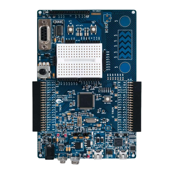
Hardware System Block Diagram The PSoC 3 Development Kit has the following sections: Power supply system ■ Programming interface ■ ■ USB communications Boost convertor ■ PSoC 3 and related circuitry ■ 32-kHz crystal ■ 24-MHz crystal ■ ® Port E (analog performance port) and port D (CapSense or generic port) ■... -
Page 15: Functional Description
Hardware Figure 4-1. PSoC 3 Development Kit Details Communication USB 9-V Battery Boost Converter 10-Pin JTAG/SWD/SWO Power Adapter Input Debug and Prog Header On-board Programming 32-kHz Crystal 24-MHz Crystal Port D (CapSense/ Port E Miscellaneous Port) (Analog Port) Reset Button Variable Resistor/ Potentiometer... - Page 16 Hardware The board power domain has five rails: Vin rail: This is where the input of the onboard regulators are connected. This domain is powered ■ through protection diodes. 5-V rail: This is the output of the 5-V regulator U2. The rail has a fixed 5-V output regardless of ■...
-
Page 17: Power Supply Jumper Settings
Hardware 4.2.1.1 Power Supply Jumper Settings Figure 4-3. Jumper Settings Two jumpers govern the power rails on the board. J10 is responsible for the selection of Vddd (digital power) and J11 selects Vdda (analog power). The jumper settings for each power scheme are as follows. Powering Scheme Jumper Settings Vdda = 5 V, Vddd = 5 V... -
Page 18: Low-Power Functionality
Hardware Port E on the board is the designated analog expansion connector. This connector brings out ports 0, 3, and 4, which are the best performing analog ports on PSoC 3 and PSoC 5 devices. Port E has two types of grounds. One is the analog ground (GND_A in the silkscreen, Vssa in the schematic), which connects directly to the analog ground on the board. -
Page 19: Jtag/Swd Programming
Hardware Figure 4-4. Onboard Programming Interface When the USB programming is plugged into the PC, it enumerates as DVKProg and you can use the normal programming interface from PSoC Creator to program this board through the onboard programmer. Pins P1[0] and P1[1] are connected to the onboard programmer. If you are using the onboard programmer, these pins should not be used for any other function. -
Page 20: Usb Communication
Hardware Figure 4-5. JTAG/SWD Programming The JTAG/SWD programming using J3 requires the MiniProg3 programmer, which can be purchased from http://www.cypress.com/go/CY8CKIT-002. 4.2.3 USB Communication The board has a USB communications interface that uses the connector, as shown in Figure 4-6. The USB connector connects to the D+ and D– lines on the PSoC to enable development of USB applications using the board. -
Page 21: Boost Convertor
Hardware Figure 4-6. USB Interface 4.2.4 Boost Convertor The PSoC 3 device has the unique capability of working from a voltage supply as low as 0.5 V. This is possible using the boost convertor. The boost convertor uses an external inductor and a diode. These components are prepopulated on the board. -
Page 22: 32-Khz And 24-Mhz Crystal
Hardware Figure 4-7. Boost Converter 4.2.5 32-kHz and 24-MHz Crystal PSoC 3 has an on-chip real time clock (RTC), which can function in sleep. This requires an external 32-kHz crystal, which is provided on the board to facilitate RTC-based designs. The PSoC 3 also has an external MHz crystal option in applications where the IMO tolerance is not satisfactory. -
Page 23: Functional Description
Hardware Figure 4-8. Schematic for Protection Circuit on 5-V Power Line Figure 4-9. Schematic for Protection Circuit on 3.3-V Power Line 4.2.6.1 Functional Description The protection circuit will protect from a maximum over-voltage or reverse-voltage of 12 V. The cut- off voltage on the 5-V line is 5.7 V and on the 3.3-V line is 3.6 V. -
Page 24: Psoc 3 Development Kit Expansion Ports
Hardware If you are using the regulator power supply from the board to power the external modules, both the P-MOS Q4 and Q5 will always be in the On state, allowing the flow of current with a maximum of 22 mV drop across the circuit when the current consumed by the external module is 150 mA. Note The working of protection circuit on the 3.3-V and 5-V lines is as described. - Page 25 Hardware The following figure shows the pin mapping for the port. Figure 4-10. Port D CY8CKIT-030 PSoC® 3 Development Kit Guide, Doc. # 001-61038 Rev. *J Arrow.com. Arrow.com. Arrow.com. Arrow.com. Arrow.com. Arrow.com. Arrow.com. Arrow.com. Arrow.com. Arrow.com. Arrow.com. Arrow.com. Arrow.com. Arrow.com. Arrow.com.
-
Page 26: Port E
Hardware 4.2.7.2 Port E This is the analog port on the kit and has special layout considerations. It also brings out all analog resources such as dedicated opamps to a single connect. Therefore, this port is ideal for precision analog design development. This port is functionally compatible to port A of the PSoC Development Kit and it is easy to port an application developed on port A. -
Page 27: Rs-232 Interface
Hardware 4.2.8 RS-232 Interface The board has an RS-232 transceiver for designs using RS-232 (UART). The RS-232 section power can be disconnected through a single resistor R58. This is useful for low-power designs. Figure 4-12. RS-232 Interface 4.2.9 Prototyping Area The prototyping area on the board has two complete ports of the device for simple custom circuit development. -
Page 28: Character Lcd
Hardware Figure 4-13. Prototyping Area This area also comprises of a potentiometer to be used for analog system development work. The potentiometer connects from Vdda, which is a noise-free supply and is hence capable of being used for low-noise analog applications. The potentiometer output is available on P6[5] and VR on header P6 in the prototyping area. -
Page 29: Capsense Sensors
Hardware Figure 4-15. LCD Connected on P8 Connector 4.2.11 CapSense Sensors The board layout considers the special requirements for CapSense. It has two CapSense buttons and a five-element CapSense slider. The CapSense buttons are connected to pins P5[6] and P5[5]. The slider elements are connected to pins P5[0:4]. -
Page 30: Code Examples
Code Examples Introduction To access code examples described in this section, open the PSoC Creator Start Page. For additional code examples, visit http://www.cypress.com. Figure 5-1. PSoC Creator Start Page 5.1.1 Programming the Code Examples Follow these steps to open and program code examples: 1. -
Page 31: Voltagedisplay
Code Examples VoltageDisplay 5.2.1 Project Description This example code measures a simple analog voltage controlled by the potentiometer. The code uses the internal Delta-Sigma ADC configured for a 20-bit operation; the ADC range is 0 to Vdda. The voltage measurement resolution is in microvolts. The results are displayed on the character LCD module. -
Page 32: Verify Output
Code Examples Range is set to Vssa to Vdda in single-ended mode because the potentiometer output is a single- ■ ended signal that can go from 0 to Vdda. Therefore, at 20-bit resolution, the ADC will resolve in steps of Vdda/2 5.2.4 Verify Output Build and program the code example, as explained in... -
Page 33: Intensityled
Code Examples IntensityLED 5.3.1 Project Description This example code uses a pulse-width modulator (PWM) to illuminate an LED. When the pulse width of the PWM varies, the LED brightness changes. By continuously varying the pulse width of the PWM, the example code makes an LED go from low brightness to a high brightness and back. 5.3.2 Hardware Connections No hardware connections are required for this project, because all the connections are hard-wired to... -
Page 34: Lowpowerdemo
Code Examples LowPowerDemo 5.4.1 Project Description This code example demonstrates the low-power functionality of PSoC 3. The project implements an RTC based code, which goes to sleep and wakes up on the basis of switch inputs. The RTC uses an accurate 32-kHz clock generated using the external crystal provided on the board. When there is a key press, the device is put to sleep while the RTC is kept active. -
Page 35: Capsense Example
CapSense buttons and one five-element slider provided on the board. Each capacitive sensor on the board is scanned using the Cypress CSD algorithm. The buttons are pre- tuned in the example code to take care of factors such as board parasitic. - Page 36 Code Examples Figure 5-7. CapSense Slider Figure 5-8. CapSense Button CY8CKIT-030 PSoC® 3 Development Kit Guide, Doc. # 001-61038 Rev. *J Arrow.com. Arrow.com. Arrow.com. Arrow.com. Arrow.com. Arrow.com. Arrow.com. Arrow.com. Arrow.com. Arrow.com. Arrow.com. Arrow.com. Arrow.com. Arrow.com. Arrow.com. Arrow.com. Arrow.com. Arrow.com. Arrow.com. Arrow.com.
-
Page 37: Adc_Dac Example
Code Examples ADC_DAC Example 5.6.1 Project Description This project demonstrates sine wave generation by using an 8-bit DAC and DMA. The sine wave period is based on the current value of the ADC value of the potentiometer. The firmware reads the voltage output by the board potentiometer and displays the raw counts on the board character LCD display. -
Page 38: Appendix
Appendix Schematics CY8CKIT-030 PSoC® 3 Development Kit Guide, Doc. # 001-61038 Rev. *J Arrow.com. Arrow.com. Arrow.com. Arrow.com. Arrow.com. Arrow.com. Arrow.com. Arrow.com. Arrow.com. Arrow.com. Arrow.com. Arrow.com. Arrow.com. Arrow.com. Arrow.com. Arrow.com. Arrow.com. Arrow.com. Arrow.com. Arrow.com. Arrow.com. Arrow.com. Arrow.com. Arrow.com. Arrow.com. Arrow.com. Arrow.com. Arrow.com. - Page 39 Appendix VDDD VDDD VCCd 0.1 uFd 0.1 uFd 1.0 uFd 1.0 uFd 0603 0603 0402 0402 ZERO ZERO 1.0 uFd 1.0 uFd VDDD VDDA 1 PIN HDR 1 PIN HDR VSSD 0603 0603 1 PIN HDR 1 PIN HDR NO LOAD VSSD 0402 0402...
- Page 40 Appendix PLACE ONE CAP PER EACH VCC ON U5. 0402 0402 0.1 uFd 0.1 uFd 0402 0402 0.1 uFd 0.1 uFd 0402 0402 0.1 uFd 0.1 uFd 0402 0402 0.1 uFd 0.1 uFd 0402 0402 0.1 uFd 0.1 uFd 0402 0402 0.1 uFd 0.1 uFd...
- Page 41 Appendix CGND1 Use Separate Track Expansion Connectors for CGND1 to GND P3[6] P3[7] P3[4] P3[5] P1[6] P1[7] P3[2] P3[3] P1[5] P3[0] P3[1] P1[2] SWDIO SWDCK P0[6] P0[7] P0[4] P0[5] P2[6] P2[7] NO LOAD P0[2] P0[3] P2[4] P2[5] NO LOAD P0[0] P0[1] P2[2] P2[3]...
- Page 42 Appendix Note: Load R72 for 5V operation, Load R71 for 3.3V operation VLCD NO LOAD V5.0 VLCD V3.3 V5.0 0805 0805 0805 0805 0402 0402 0.1 uFd 0.1 uFd NO LOAD VSSD 100 ohm 100 ohm 10K R69 VBUS2 R/nW R/nW VBUS VSSD...
-
Page 43: Board Layout
Appendix Board Layout A.2.1 PDC-09589 Top CY8CKIT-030 PSoC® 3 Development Kit Guide, Doc. # 001-61038 Rev. *J Arrow.com. Arrow.com. Arrow.com. Arrow.com. Arrow.com. Arrow.com. Arrow.com. Arrow.com. Arrow.com. Arrow.com. Arrow.com. Arrow.com. Arrow.com. Arrow.com. Arrow.com. Arrow.com. Arrow.com. Arrow.com. Arrow.com. Arrow.com. Arrow.com. Arrow.com. Arrow.com. Arrow.com. -
Page 44: Pdc-09589 Power
Appendix A.2.2 PDC-09589 Power CY8CKIT-030 PSoC® 3 Development Kit Guide, Doc. # 001-61038 Rev. *J Arrow.com. Arrow.com. Arrow.com. Arrow.com. Arrow.com. Arrow.com. Arrow.com. Arrow.com. Arrow.com. Arrow.com. Arrow.com. Arrow.com. Arrow.com. Arrow.com. Arrow.com. Arrow.com. Arrow.com. Arrow.com. Arrow.com. Arrow.com. Arrow.com. Arrow.com. Arrow.com. Arrow.com. Arrow.com. Arrow.com. -
Page 45: Pdc-09589 Ground
Appendix A.2.3 PDC-09589 Ground CY8CKIT-030 PSoC® 3 Development Kit Guide, Doc. # 001-61038 Rev. *J Arrow.com. Arrow.com. Arrow.com. Arrow.com. Arrow.com. Arrow.com. Arrow.com. Arrow.com. Arrow.com. Arrow.com. Arrow.com. Arrow.com. Arrow.com. Arrow.com. Arrow.com. Arrow.com. Arrow.com. Arrow.com. Arrow.com. Arrow.com. Arrow.com. Arrow.com. Arrow.com. Arrow.com. Arrow.com. Arrow.com. -
Page 46: Pdc-09589 Bottom
Appendix A.2.4 PDC-09589 Bottom CY8CKIT-030 PSoC® 3 Development Kit Guide, Doc. # 001-61038 Rev. *J Arrow.com. Arrow.com. Arrow.com. Arrow.com. Arrow.com. Arrow.com. Arrow.com. Arrow.com. Arrow.com. Arrow.com. Arrow.com. Arrow.com. Arrow.com. Arrow.com. Arrow.com. Arrow.com. Arrow.com. Arrow.com. Arrow.com. Arrow.com. Arrow.com. Arrow.com. Arrow.com. Arrow.com. Arrow.com. Arrow.com. -
Page 47: Bill Of Materials (Bom)
Appendix Bill of Materials (BOM) Item Qty Reference Value Description Manufacturer Mfr Part Number BAT 9V MALE BATTERY HOLDER 9V Keystone Electronics 593 Male PC MT BAT 9V BATTERY HOLDER 9V Keystone Electronics 594 FEMALE Female PC MT C2,C4,C5,C13,C14, 10 uFd 16v CAP 10UF 16V TANTALUM TAJA106K016R C15,C28,C45,C46... - Page 48 Appendix Item Qty Reference Value Description Manufacturer Mfr Part Number TP1, J26, J27, J35, BLACK TEST TEST POINT PC MINI Keystone Electronics 5001 POINT .040"D Black LED1,LED2,LED3,L LED Red LED RED CLEAR 0805 Rohm SML-210LTT86 Semiconductor 22 uH INDUCTOR SHIELD PWR TDK Corporation SLF7032T- 22UH 7032...
- Page 49 Microchip 24LC00/SN 400KHZ 8SOIC Technology LM1117MPX- IC REG 3.3V 800MA LDO National LM1117IMP-3.3/ SOT-223 Semiconductor NOPB CY7C68013A- IC, FX2 HIGH-SPEED USB Cypress CY7C68013A- 56LTXC PERIPHERAL Semiconductor 56LTXC CONTROLLER QFN56 CY8C3866AXI- PSoC3 Mixed-Signal Array Cypress CY8C3866AXI-040 040 TQFP100 Semiconductor MAX3232CDR IC 3-5.5V LINE DRVR/...
- Page 50 Appendix Item Qty Reference Value Description Manufacturer Mfr Part Number 2p_jumper CONN HEADER VERT SGL 961102-6404-AR 2POS GOLD 3.3V LCD 3.3V LCD Module 16POS w/ Lumex LCM-S01602DTR/A- Module 16POS 16 pin header installed w/16 pin header installed 16 pin header CONN HEADER VERT 961116-6404-AR SGL 16POS GOLD...
- Page 51 Item Qty Reference Value Description Manufacturer Mfr Part Number 50MIL KEYED CONN HEADER 10 PIN Samtec FTSH-105-01-L-DV- 50MIL KEYED SMD CSB1,CSB2 CapSense CapSense Button Cypress CSS1 CapSense CapSense Slider Cypress Linear Slider 5 J9,J13,J15,J17,J19, PADS PADS J20,J21,J23,J24,J4 1,J42 TV1,TV2 PADS PADS Install On Bottom of PCB As Close To Corners As Possible BUMPER CLEAR .500X.23"...
-
Page 52: Pin Assignment Table
Appendix Pin Assignment Table Port Pin Name Description P0[0] Connected to pin 18 on port E P0[1] Connected to pin 17 on port E P0[2] Connected to pin 16 on port E Connected to two points: P0[3] 1. Voltage reference chip* Port 0 2. - Page 53 Appendix Port Pin Name Description Connected to two points: P2[0] 1. Connected to LCD module 2. Connected to pin 18 on port D Connected to two points: P2[1] 1. Connected to LCD module 2. Connected to pin 17 on port D Connected to two points: P2[2] 1.
- Page 54 Appendix Port Pin Name Description Connected to two points: P5[0] 1. Connected to CapSense slider segment 2. Connected to pin 28 on port D Connected to two points: P5[1] 1. Connected to CapSense slider segment 2. Connected to pin 27 on port D Connected to two points: P5[2] 1.
- Page 55 Appendix Port Pin Name Description Vbat Connected to Vbat Vboost Connected to Vboost VCCa Connected to VCCa VCCd Connected to VCCd VCCd Connected to VCCd VDDa Connected to VDDa VDDd Connected to VDDd VDDd Connected to VDDd VDDio0 Connected to VDDio0 VDDio1 Connected to VDDio1 VDDio2...
-
Page 56: Using Rbleed Resistor For Capsense
Appendix Using RBLEED Resistor for CapSense An RBLEED resistor value of 2.2 K provides good SNR values for the onboard CapSense buttons and sliders. However, tuning CapSense with a fixed RBLEED value is difficult because the analog switch divider and scan resolution are the only tunable parameters. For onboard CapSense buttons and sliders, with RBLEED of 2.2 K, the following SNR is achieved. -
Page 57: Revision History
Revision History CY8CKIT-030 PSoC® 3 Development Kit Guide Revision History Document Title: CY8CKIT-030 PSoC® 3 Development Kit Guide Document Number: 001-61038 Origin of Revision ECN# Issue Date Description of Change Change 3159150 01/06/2011 Initial version of kit guide. Updated Appendix chapter on page 3243290 04/28/2011 RKAD Updated... - Page 58 Revision History CY8CKIT-030 PSoC® 3 Development Kit Guide Revision History (continued) Document Title: CY8CKIT-030 PSoC® 3 Development Kit Guide Document Number: 001-61038 Origin of Revision ECN# Issue Date Description of Change Change Updated Kit Operation chapter on page Updated “Programming PSoC 3 Device” on page 4131903 09/23/2013 SASH Updated description (Added programming steps).
Need help?
Do you have a question about the PSoC CY8CKIT-030 and is the answer not in the manual?
Questions and answers