Table of Contents
Advertisement
Quick Links
Advertisement
Table of Contents

Related Manuals for ABB i-bus KNX ABA/S 1.2.1


Summary of Contents for ABB i-bus KNX ABA/S 1.2.1
- Page 1 — PRODUCT MANUAL ® ABB i-bus ABA/S 1.2.1 Logic Controller...
-
Page 3: Table Of Contents
® ABB i-bus Contents Page Contents General ....................7 Using the product manual ......................7 Legal disclaimer ........................... 7 Explanation of symbols ........................ 7 Safety ....................9 General safety instructions ......................9 Proper use ........................... 9 Cyber security (network security) ....................9 Restrict access to the various media ................... - Page 4 ® ABB i-bus Contents Commissioning .................. 27 Commissioning requirement ...................... 27 Commissioning overview ......................27 Assignment of the physical address................... 27 6.3.1 Network settings ........................28 Software/application........................28 6.4.1 Download response ........................28 Parameters ..................29 General ............................29 User interface – menu description ..................... 30 7.2.1...
- Page 5 ® ABB i-bus Contents 7.10.21 Addition (ADD) ..........................65 7.10.22 Multiplication (MULT) ........................66 7.10.23 Subtraction (SUB) ........................67 7.10.24 Division (DIV) ..........................68 7.10.25 Modulo (MOD) ..........................69 7.10.26 Delay (DELAY) ...........................70 7.10.27 Staircase Light (STAIRC LIGHT) ....................72 7.10.28 Calendar, simple (CALENDAR_S) .....................74 7.10.29 Calendar (CALENDAR) ......................76...
-
Page 7: General
We reserve the right to make technical changes or modify the contents of this document without prior notice. The agreed properties are definitive for any orders placed. ABB AG accepts no responsibility whatsoever for potential errors or possible lack of information in this document. - Page 8 ® ABB i-bus General Notes and warnings are represented as follows in this manual: DANGER – This symbol is a warning about electrical voltage and indicates high-risk hazards that will definitely result in death or serious injury unless avoided. DANGER –...
-
Page 9: Safety
The industry is increasingly faced with cyber security risks. To make its solutions more stable, secure and robust, ABB has officially added cyber security tests to its product development process. In addition, the information below includes guidelines and mechanisms that you can use to improve the security of KNX systems. -
Page 10: Twisted Pair Cabling
® ABB i-bus Safety Twisted pair cabling ► The ends of KNX twisted pair cables should not be visible or protrude from the wall either inside or outside the building. ► If available, use the anti-theft devices on the application modules. -
Page 11: Product Overview
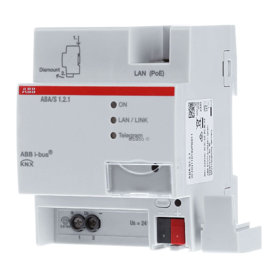
® ABB i-bus Product Overview Product Overview Product Overview The device is a modular installation device (MDRC) in Pro M design. The module width of the device is four space units. It is designed for installation in distribution boards on 35 mm mounting rails. -
Page 12: Logic Controller Aba/S 1.2.1, Mdrc
Ethernet (PoE). We recommend using a power supply from our range. When using timer functions, date and time must be provided via KNX/TP. ® The device connects to the ABB i-bus KNX via the front bus connection terminal. Engineering Tool Software (ETS) is used for physical address assignment and parametrization. -
Page 13: Dimension Drawing
® ABB i-bus Product Overview 3.3.1 Dimension drawing Fig. 2: Dimension drawing ABA/S 1.2.1 | 2CDC509086D0201 13... -
Page 14: Connection Diagram
® ABB i-bus Product Overview 3.3.2 Connection diagram Fig. 3: ABA/S 1.2.1 connection diagram Legend Label carrier Ethernet/LAN connection KNX programming LED (red) On LED (green) KNX programming button LAN/LINK LED (yellow) KNX connection KNX telegram LED (yellow) Cover cap... -
Page 15: Operating And Display Elements
® ABB i-bus Product Overview 3.3.3 Operating and display elements Button/LED Description LED indicator Assignment of the physical On: Device is in programming mode address Off: No auxiliary voltage (24 V or PoE) available On: System initialized Flashing slowly (1 Hz): System starting up... -
Page 16: Technical Data
® ABB i-bus Product Overview 3.3.4 Technical data 3.3.4.1 General technical data Supply Bus voltage 21…32 V DC Current consumption, bus < 12 mA Leakage loss, bus Maximum 250 mW Leakage loss, device Maximum 3 W Auxiliary voltage U 24 V DC (+20% / -15%) or PoE (IEEE 802.3af class 2) - Page 17 ® ABB i-bus Product Overview Temperature range Operation -5...+45 °C Transport -25...+70 °C Storage -25...+55 °C Ambient conditions Maximum air humidity 93 %, no condensation allowed Atmospheric pressure Atmosphere up to 2,000 m Design Modular installation device (MDRC) Modular installation device...
-
Page 18: Device Type
ETS and the current version of the device application are required for programming. The latest version of the application and corresponding software information is available for download from www.abb.com/knx. After import into ETS, it appears in the Catalogs window under Manufacturers/ABB/Controller/Controller Output. -
Page 19: Description Of Inputs And Outputs
® ABB i-bus Product Overview 3.3.4.3 Description of inputs and outputs SELV 24 V DC supply voltage input Only a 24 V DC voltage may be connected to the power supply input. We recommend using a power supply from our range. -
Page 21: Function
® ABB i-bus Function Function Overview The device provides a comprehensive range of logic functions. It requires an auxiliary voltage, either 24 V DC or Power over Ethernet (PoE). We recommend using a power supply from our range. When using timer functions, date and time must be provided via KNX/TP. -
Page 22: Input Functions
Tool interface capable of detecting the device on the network (IP discovery) and updating firmware if required. ® You can download the i-bus Tool free of charge from our homepage (www.abb.de/knx). ® A description of the functions is provided in the i-bus Tool online help. -
Page 23: Special Operating States
® ABB i-bus Function Special operating states 4.6.1 Reaction on bus voltage failure/recovery, download and ETS reset The device's reaction on bus voltage failure/recovery, download and ETS reset can be set in the device parameters. If the power fails (24 V DC or PoE), the device safeguards certain internally calculated values, e.g. -
Page 24: Ets Reset
® ABB i-bus Function 4.6.1.3 ETS reset Generally an ETS reset is defined as a reset of the device via ETS. To trigger an ETS reset, go to the ETS Commissioning menu and select Reset device. This deletes all internal information and stops and restarts the device. -
Page 25: Mounting And Installation
® ABB i-bus Mounting and installation Mounting and installation Information about mounting The installation position can be selected as required. To connect the device to the electrical system, use screw terminals. To connect it to the bus, use the supplied bus connection terminal. The terminal assignment is located on the housing. -
Page 26: Mounting On Din Rail
® ABB i-bus Mounting and installation Mounting on DIN rail The device is fitted and removed without auxiliary tools. Make sure the device is accessible for operation, testing, visual inspection, maintenance and repair. Fig. 4: Mounting on DIN rail Place the DIN rail holder on the upper edge of the DIN rail and push down. -
Page 27: Commissioning
Commissioning Commissioning requirement ® To commission the device, a PC with ETS is required along with a connection to the ABB i-bus , e.g. via a KNX interface. Once the bus and auxiliary voltages are connected, the device is ready for operation. -
Page 28: Network Settings
® ABB i-bus Commissioning 6.3.1 Network settings DHCP ("Obtain an IP address automatically") is enabled on the device as standard. So the device obtains its IP address from a DHCP server which is often integrated into a network switch or router. If there is no DHCP server, the device is assigned an automatic IP address, usually 169.254.xxx.yyy. -
Page 29: Parameters
General ETS Engineering Tool Software is used to parametrize the device. The device uses an ETS plug-in. In ETS, the application is located in the Catalogs window under Manufacturers/ABB/Controller/Controller. The following sections describe the device functions and parameters. ABA/S 1.2.1 | 2CDC509086D0201 29... -
Page 30: User Interface - Menu Description
® ABB i-bus Parameters User interface – menu description 7.2.1 File menu Save Save can only be used after a change. Export Exports the whole project to an XML file. Linked group addresses are not exported along with it. If you wish to copy a project with the group addresses, you can do so using the Copy function in ETS. -
Page 31: Edit Menu
® ABB i-bus Parameters 7.2.2 Edit menu Grid Switches the worksheet grid on and off. Create composite Creates a composite function block from the selected logic. function block More information Cut/Copy/Paste Standard functionality Undo/Redo Standard functionality 15 undos/redos are possible. -
Page 32: Worksheet
® ABB i-bus Parameters 7.2.5 Worksheet The worksheet is where you create logical links. To create a new worksheet, click the "+" symbol. To rename the worksheet, double-click the tab field and overwrite it. Fig. 6: Worksheet 7.2.6 Properties window The Properties window is used to parametrize logic elements. -
Page 33: Monitor
® ABB i-bus Parameters Monitor The Monitor function provides a real-time view of the current states of the logic in a device. For this to work, the device must be connected to the network. To start the Monitor, click the following icon: Fig. -
Page 34: Simulation
® ABB i-bus Parameters Simulation Fig. 8: Simulation Simulation/Stop Starts and stops the simulation. Speeds Used to select simulation speeds. Important for simulating timer functions such as Calendar. Single Step Clicking Next Step starts a calculation cycle. Slow Around 50 times slower than real time. -
Page 35: Engine Settings Parameters
® ABB i-bus Parameters Engine settings parameters 7.5.1 Cycle time Options: 200...65535 (unsigned integer) Defines the minimum time for the logic engine calculation cycle. 7.5.2 Use persisting values Options: no (no checkmark) yes (checkmark) • yes: The device stores the internal information of certain function elements. To see which data are saved, please refer to the descriptions for the relevant function elements. -
Page 36: In Operation Parameters
® ABB i-bus Parameters In operation parameters 7.7.1 Send Group Object "In Operation" (1-bit) Options: Send value 0 cyclically Send value 1 cyclically The In operation group object indicates that the device is communicating correctly with the KNX bus. Depending on the setting, a 0 or 1 is sent cyclically and activates the 1-bit group object In operation. -
Page 37: General Information On Logic Calculation
® ABB i-bus Parameters General information on logic calculation The logic controller calculates generated logic cyclically. The default engine cycle time setting is 200 ms but this can be increased if required. See Cycle time. Logic is always calculated from the inputs to the outputs (left to right). There is no loop capability. -
Page 38: Description Of Function Elements
® ABB i-bus Parameters 7.10 Description of function elements 7.10.1 KNX input (KNX IN) Description Selects the KNX input element based on the required datapoint type. Received values are sent to the logic engine. Enables a corresponding group object in ETS. - Page 39 ® ABB i-bus Parameters Description of parameters Initial value: Initial value of the input. May only be used in combination with the Set initial value after restart parameter. Set initial value after restart: If the checkbox is selected for this parameter, the input will have the defined initial value on restart. If it is not, the device first tries to restore the input value.
- Page 40 ® ABB i-bus Parameters Element display • Element name • First group address • Data widths (1 bit, 2 bits, 4 bits, 1 byte, 2 bytes, 4 bytes, date, time, date/time, color) Note The first group address is the one that sends a value. The group addresses are displayed in the same layout as in ETS (e.g.
-
Page 41: Knx Output (Knx Out)
® ABB i-bus Parameters 7.10.2 KNX output (KNX OUT) Description Selects the KNX output element based on the required datapoint type. Received values from the logic engine are forwarded. Enables a corresponding group object in ETS. Note You can enter a unique name for the element in the Name field in the properties. The name will also be written into the Group Object Description in ETS. - Page 42 ® ABB i-bus Parameters Description of parameters Change in %: The value change is defined as follows: (NEW_VALUE – LAST_SENT_VALUE) / LAST_SENT_VALUE If NEW_VALUE = LAST_SENT_VALUE = 0, result is 0% If NEW_VALUE <> 0 and LAST_SENT_VALUE = 0, result is 100% Function Whenever a telegram is received the output starts a recalculation independently if the value has changed.
-
Page 43: Marker Input (Marker In)
® ABB i-bus Parameters 7.10.3 Marker Input (MARKER IN) Description Markers are used for distant links. Links between worksheets are also possible. A Marker Input is logically linked to a Marker Output. Important: A Marker Input can only be linked to exactly one Marker Output! -
Page 44: Marker Output (Marker Out)
® ABB i-bus Parameters 7.10.4 Marker Output (MARKER OUT) Description Markers are used for distant links. Links between worksheets are also possible. A Marker Output is logically linked to one or more Marker Inputs. Note For easy identification you should enter a unique name for the corresponding marker in the Name field in the properties. -
Page 45: And (And)
® ABB i-bus Parameters 7.10.5 AND (AND) Description Logical AND link Inputs Abbr. Name Visible Description 1 bit Input Always 1 bit Input Always 3-16 1 bit Input Parametrizable n = 3...16 Outputs Abbr. Name Visible Description 1 bit Output... -
Page 46: Or (Or)
® ABB i-bus Parameters 7.10.6 OR (OR) Description Logical OR link Inputs Abbr. Name Visible Description 1 bit Input Always 1 bit Input Always 3-16 1 bit Input Parametrizable n = 3...16 Outputs Abbr. Name Visible Description 1 bit Output... -
Page 47: Xor (Xor)
® ABB i-bus Parameters 7.10.7 XOR (XOR) Description Logical XOR link (Exclusive OR). Inputs Abbr. Name Visible Description 1 bit Input Always 1 bit Input Always 3-16 1 bit Input Parametrizable n = 3...16 Outputs Abbr. Name Visible Description 1 bit... -
Page 48: Not (Not)
® ABB i-bus Parameters 7.10.8 NOT (NOT) Description Logical link which inverts the input value (negation). Inputs Abbr. Name Visible Description 1 bit Input Always Outputs Abbr. Name Visible Description 1 bit Output Always Note You can invert 1-bit inputs and outputs by double-clicking on the relevant I/O. -
Page 49: 1Ofn (One-Hot)
® ABB i-bus Parameters 7.10.9 1ofN (ONE-HOT) Description Logical 1ofN link. Inputs Abbr. Name Visible Description 1 bit Input Always 1 bit Input Always 3-16 1 bit Input Parametrizable n = 3...16 Outputs Abbr. Name Visible Description 1 bit Output... - Page 50 ® ABB i-bus Parameters Use Case You want to ensure that from a set of signals, exactly one is 1 while the others are 0. The switching shown ensures that this is the case. Fig. 11: Use case, 1ofN element If more than one of the three input values is 1, this results in a 1ofN link of 0.
-
Page 51: Greater Than (Greater)
® ABB i-bus Parameters 7.10.10 Greater Than (GREATER) Description Compares two input values. Both inputs can also be linked with fixed values (constant). Inputs Abbr. Name Visible Description Numeric value Input Always Same as Input 1 Input Parametrizable Outputs Abbr. -
Page 52: Lower Than (Lower)
® ABB i-bus Parameters 7.10.11 Lower Than (LOWER) Description Compares two input values. Both inputs can also be linked with fixed values (constant). Inputs Abbr. Name Visible Description Numeric value Input Always Same as Input 1 Input Parametrizable Outputs Abbr. -
Page 53: Equal (Equal)
® ABB i-bus Parameters 7.10.12 Equal (EQUAL) Description Compares two input values. Both inputs can also be linked with fixed values (constant). Inputs Abbr. Name Visible Description Numeric value Input Always Same as Input 1 Input Parametrizable Outputs Abbr. Name... -
Page 54: Not Equal (Not Equal)
® ABB i-bus Parameters 7.10.13 Not Equal (NOT EQUAL) Description Compares two input values. Both inputs can also be linked with fixed values (constant). Inputs Abbr. Name Visible Description Numeric value Input Always Same as Input 1 Input Parametrizable Outputs Abbr. -
Page 55: Greater Or Equal (Greater/Equal)
® ABB i-bus Parameters 7.10.14 Greater or Equal (GREATER/EQUAL) Description Compares two input values. Both inputs can also be linked with fixed values (constant). Inputs Abbr. Name Visible Description Numeric value Input Always Same as Input 1 Input Parametrizable Outputs Abbr. -
Page 56: Lower Or Equal (Lower/Equal)
® ABB i-bus Parameters 7.10.15 Lower or Equal (LOWER/EQUAL) Description Compares two input values. Both inputs can also be linked with fixed values (constant). Inputs Abbr. Name Visible Description Numeric value Input Always Same as Input 1 Input Parametrizable Outputs Abbr. -
Page 57: Minimum/Maximum (Min/Max)
® ABB i-bus Parameters 7.10.16 Minimum/Maximum (MIN/MAX) Description Finds the largest or smallest of up to 16 values. The inputs can also be linked with fixed values (constant). Inputs Abbr. Name Visible Description 1 bit Function Parametrizable Input value Always... - Page 58 ® ABB i-bus Parameters Function Input F defines, if MIN or MAX function is activated. If F = 0, the output sends the largest input value (E1-E16). Function MAX is activated. If F = 1, the output sends the smallest input value (E1-E16). Function MIN is activated.
-
Page 59: Multiplexer, 2 To 1 (1-Mux)
® ABB i-bus Parameters 7.10.17 Multiplexer, 2 to 1 (1-MUX) Description Selects one of two input values. Inputs Abbr. Name Visible Description 1 bit Select Always Input value Always Input value Always Outputs Abbr. Name Visible Description 1 bit Output... - Page 60 ® ABB i-bus Parameters Function If Select is 1, input I is sent to the output. If Select is 0, input I is sent to the output. Values received on unselected inputs are stored until the input is selected. Whenever a telegram is received the output starts a recalculation independently if the value has changed.
-
Page 61: Multiplexer, N-Fold (N-Mux)
® ABB i-bus Parameters 7.10.18 Multiplexer, n-fold (n-MUX) Description Selects a value from up to 16 input values. Inputs Abbr. Name Visible Description 1 byte unsigned 2 byte unsigned Select Always 4 byte unsigned Input value Always Input value Always... - Page 62 ® ABB i-bus Parameters Function The Select value defines which input value is sent to the output. Values received on unselected inputs are stored until the input is selected. The output is recalculated and updated every time if any of the inputs or Select receives a value.
-
Page 63: Gate (Gate)
® ABB i-bus Parameters 7.10.19 Gate (GATE) Description Disables or enables the transmission of values. If the Gate is disabled, the output remains unchanged and will not trigger a recalculation. Inputs Abbr. Name Invertible Visible Description Input Always 1 bit... -
Page 64: Filter (Filter)
® ABB i-bus Parameters 7.10.20 Filter (FILTER) Description The filter blocks 1-bit telegram values (0 or 1). Inputs Abbr. Name Invertible Visible Description 1 bit Input Always Outputs Abbr. Name Invertible Visible Description 1 bit Output Always Parameters Name Value... -
Page 65: Addition (Add)
® ABB i-bus Parameters 7.10.21 Addition (ADD) Description Sums up to 16 input values. Inputs Abbr. Name Visible Description 8 bit or higher Augend Always Same as Input 1 Addend Always Same as Input 1 Addend Parametrizable n = 2...15 Outputs Abbr. -
Page 66: Multiplication (Mult)
® ABB i-bus Parameters 7.10.22 Multiplication (MULT) Description Multiplies up to 16 input values. Inputs Abbr. Name Visible Description 8 bit or higher Multiplicand Always Same as Input 1 Multiplier Always 3-16 Same as Input 1 Multiplier Parametrizable n = 2…15 Outputs Abbr. -
Page 67: Subtraction (Sub)
® ABB i-bus Parameters 7.10.23 Subtraction (SUB) Description Subtracts one input value (Subtrahend) from another (Minuend). Inputs Abbr. Name Visible Description 8 bit or higher Minuend Always Same as Input 1 Subtrahend Always Outputs Abbr. Name Visible Description Same as Input 1... -
Page 68: Division (Div)
® ABB i-bus Parameters 7.10.24 Division (DIV) Description Divides one input value (Dividend) by another (Divisor). Inputs Abbr. Name Visible Description 8 bit or higher Dividend Always Same as Input 1 Divisor Always Outputs Abbr. Name Visible Description Same as Input 1... -
Page 69: Modulo (Mod)
® ABB i-bus Parameters 7.10.25 Modulo (MOD) Description Calculates the remainder from dividing one input value (Dividend) by another (Divisor). Inputs Abbr. Name Visible Description 8 bit or higher Dividend Always Same as Input 1 Divisor Always Outputs Abbr. Name... -
Page 70: Delay (Delay)
® ABB i-bus Parameters 7.10.26 Delay (DELAY) Description Received values are forwarded after a defined delay. Inputs Abbr. Name Visible Description Input Always Value in seconds; 4 byte signed Delay Parametrizable according to KNX DPT 13.100 Outputs Abbr. Name Visible... - Page 71 ® ABB i-bus Parameters Function If a new value is received during the delay time, the delay restarts and the old value is discarded. The timer resets to zero and restarts (Retrigger). Once the delay time has elapsed, the last input value is updated to the output value.
-
Page 72: Staircase Light (Stairc Light)
® ABB i-bus Parameters 7.10.27 Staircase Light (STAIRC LIGHT) Description A timer which automatically resets the output to 0 (false) after a specified time has elapsed. Inputs Abbr. Name Visible Description 1 bit Trigger Always Value in seconds; 4 byte unsigned... - Page 73 ® ABB i-bus Parameters Function • Input receives a 1 (true): Output = 1 (true) Timer restarts • Input receives a 0 (false): Output = 0 (false) Timer stops • If the timer reaches the On-time: Output = 0 (false) Timer stops •...
-
Page 74: Calendar, Simple (Calendar_S)
® ABB i-bus Parameters 7.10.28 Calendar, simple (CALENDAR_S) Description Simple comparison of a start time and an end time. Triggers daily events (for the whole day or at specific times). The output value is 1 if the device time is between Start and End and the other conditions are met. - Page 75 ® ABB i-bus Parameters Function • If the current time is between the Start and End times AND the Active input = 1 (true): Output = 1 (true) • Start time greater than End time: Output = 0 (false) •...
-
Page 76: Calendar (Calendar)
® ABB i-bus Parameters 7.10.29 Calendar (CALENDAR) Description Used for events that occur periodically or on specific dates. A wide variety of settings is possible. The calendar uses the logic controller's internal clock. It can be changed via the bus (group objects). - Page 77 ® ABB i-bus Parameters Daily recurrence field Abbr. Name Visible Description 1 byte Parametrizable Every ... day(s) unsigned Weekly recurrence fields Abbr. Name Visible Description Bit field input: defines the weekday(s) when the element is active. 1 byte Bit 0 = Monday...
- Page 78 ® ABB i-bus Parameters Parameters The Time section defines the time of day when the output is 1, otherwise the output is 0. The Recurrence section is for setting the days on which the element is active. On these days the output value is 1.
- Page 79 ® ABB i-bus Parameters Recurrence – Daily section parameters Recurrence cycle in days. Fig. 14: Recurrence section parameters – Daily Parameter Name Value Description The element is activated on specific days, e.g. every 4th day. Every ... day(s) Option 1...500, default = 1 Every ...
- Page 80 ® ABB i-bus Parameters Recurrence – Weekly section parameters Recurrence cycle in weeks. Days of the week on which an event should be triggered every x weeks. Fig. 15: Recurrence section parameters – Weekly Parameter Name Value Description Every ... week(s) The element is activated in specific weeks, e.g.
- Page 81 ® ABB i-bus Parameters Recurrence – Monthly section parameters Recurrence cycle in months. The day of the month on which an event should be triggered every x months. Fig. 16: Recurrence section parameters – Monthly Parameter Name Value Description The element is activated on a specific day in a Day ...
- Page 82 ® ABB i-bus Parameters Recurrence – Yearly section parameters Recurrence cycle in years. The day of a month on which an event should be triggered every x years. Fig. 17: Recurrence section parameters – Yearly Parameter Name Value Description The element is activated in specific years, e.g.
- Page 83 ® ABB i-bus Parameters Duration section parameters Before the start date the calendar function is inactive. After the end date the calendar function is inactive. If no end date is defined the Calendar function is active from the start date onward.
- Page 84 ® ABB i-bus Parameters Selecting "As input" The settings concerned are disabled and the parameters can be set via the inputs. Fig. 19: Selecting "As input" Start-up behavior The element will not be active unless a valid date and/or time are provided via the Start and End fields.
-
Page 85: Numeric Converter (N-Conv)
® ABB i-bus Parameters 7.10.30 Numeric Converter (N-CONV) Description The converter allows you to link different datapoint types and convert them. Basics on datapoint types The KNX specification distinguishes between main datapoint types and sub types, e.g.: Main DPT type... - Page 86 ® ABB i-bus Parameters Inputs Abbr. Name Visible Description See above Input Always See above Factor Parametrizable See above Offset Parametrizable Outputs Abbr. Name Visible Description See above Output Always Parameters Name Value Visible Description Factor Single Float Always Enables Factor input...
-
Page 87: Rs Flip Flop (Rs-Ff)
® ABB i-bus Parameters 7.10.31 RS Flip Flop (RS-FF) Description Stores input statuses and resets them on request. Inputs No. DPT Abbr. Name Visible Description 1 bit Always A value of 1 sets the Flip Flop output to 1. A value of 1 resets the Flip Flop output to 0... - Page 88 ® ABB i-bus Parameters Function Use of Flip Flop e.g. as an alarm memory. No output value is actively set for the output. Contingent initial values set can trigger an output change when the inputs receive an incoming signal. Note As long as input R = 1, the output is always 0.
-
Page 89: Up Counter (Up Count)
® ABB i-bus Parameters 7.10.32 Up Counter (UP COUNT) Description Counts upward from 0 to an adjustable threshold. Only counts value changes from 0 to 1. Inputs No. DPT Abbr. Name Visible Description Trigger input. 1 bit Trigger Always Value change from 0 to 1 increments the counter by 1. - Page 90 ® ABB i-bus Parameters Function • The counter adds increments when a value changes from 0 to 1 (rising edge). • The counter counts upward from 0 to an adjustable threshold. If it reaches this threshold, the counter stops and the Overflow output receives a value of 1 (true) on the next rising edge.
-
Page 91: Pid Controller (Pid)
® ABB i-bus Parameters 7.10.33 PID controller (PID) Description The controller calculates the output value from the difference between the Setpoint and the Actual Value. The control parameters are Proportional Coefficient, Integral Time and Derivative Time. Inputs No. DPT Abbr. - Page 92 ® ABB i-bus Parameters Parameters Name Value Visible Description - Proportional (P) - Integral (PI) Controller type Always - Derivative (PD) - PID Float value, Proportional Always Coefficient default = 60 Float value in [min], If Controller Integral time in [s]; typical...
- Page 93 ® ABB i-bus Parameters Function Schematic diagram of controller: Fig. 20: Schematic diagram of controller Algorithms: • ControlValue = ProportionalValue + IntegralValue + DerivativeValue • ProportionalValue = Deviation x ProportionalCoefficient • IntegralValue = IntegralValueOld + Deviation x CycleTime / IntegralTime •...
-
Page 94: Constant (Const)
® ABB i-bus Parameters 7.10.34 Constant (CONST) Description The constant can be used, for example, for the purposes of comparison with other input variables. The constant never triggers a recalculation. Outputs No. DPT Abbr. Name Visible Description Output Always Parameters... -
Page 95: Website Input (Web In)
® ABB i-bus Parameters 7.10.35 Website Input (WEB IN) Description Generates an input value via the web browser ("WebUI"). This element adds a corresponding entry for value input in the WebUI. Entered values will be sent to the logic engine. -
Page 96: Website Output (Web Out)
® ABB i-bus Parameters 7.10.36 Website Output (WEB OUT) Description Generates an output value via the web browser ("WebUI"). This can be displayed but not edited. Inputs No. DPT Abbr. Name Visible Description Always Displayed value Parameters Name Value Visible... -
Page 97: Function Block Input (Fb In)
® ABB i-bus Parameters 7.10.37 Function Block Input (FB IN) Description The input of a user-defined function block. If you wish to use the same logic several times, you can combine and save it in a function block. In such cases the function block input is used in place of a KNX input. -
Page 98: Function Block Output (Fb Out)
® ABB i-bus Parameters 7.10.38 Function Block Output (FB OUT) Description The output of a user-defined function block. If you wish to use the same logic several times, you can combine and save it in a function block. In such cases the function block output is used in place of a KNX output. -
Page 99: Composite Function Blocks
® ABB i-bus Parameters 7.10.39 Composite function blocks If you wish to use the same logic function several times, you can combine and save it in a composite function block. How to create a composite function block: • Create a logic engine with "normal" KNX inputs and outputs, and use Simulation to check that it is working. - Page 100 ® ABB i-bus Parameters • The following dialog window appears: Fig. 22: Creating composite function blocks Enter the data saved with the function block. The title must be unique. • Click OK. The composite function block is now stored and recallable in Own function blocks on the left in the Element Selector window.
- Page 101 ® ABB i-bus Parameters Exporting composite function blocks: • Select the composite function block in Own function blocks. Fig. 23: Exporting own function blocks • Select Export function block. • The following dialog window appears: Fig. 24: Own function blocks - destination file Enter a name for the destination file.
-
Page 102: Comment
® ABB i-bus Parameters 7.10.40 Comment The Comment element can be saved with a logical link in order to explain it. You can adjust the angle of rotation, width and height by dragging and dropping with the left-hand mouse button, or in the Properties window. -
Page 103: Group Objects
® ABB i-bus Group objects Group objects Summary of group objects Object Function Name Length Flags C R W T U 1…500 Applied from the logic editor Blank Configuration- Configuration- X X X dependent dependent In operation General 1,001 1 bit... -
Page 104: Inputs And Outputs
® ABB i-bus Group objects Inputs and outputs Object Function Name Data type Flags 1…500 Applied from the logic editor Blank According to the C, R, W, T definition in the logic editor This group object is defined via the logic editor. -
Page 105: Operation
® ABB i-bus Operation Operation Manual operation Not relevant for this device. ABA/S 1.2.1 | 2CDC509086D0201 105... -
Page 107: Maintenance And Cleaning
® ABB i-bus Maintenance and cleaning Maintenance and cleaning 10.1 Maintenance The device is maintenance-free. In the event of damage (e.g. during transport and/or storage), do not carry out any repairs. 10.2 Cleaning The voltage supply to the device must be switched off before cleaning. If devices become dirty, they can be cleaned using a dry cloth or a cloth dampened with a soapy solution. -
Page 109: Disassembly And Disposal
® ABB i-bus Disassembly and disposal Disassembly and disposal 11.1 Removal Fig. 25: Removal Press on the top of the device. Release the bottom of the device from the DIN rail. Lift the device up and off the DIN rail. -
Page 110: Environment
® ABB i-bus Disassembly and disposal 11.2 Environment Consider environmental protection. Used electrical and electronic devices must not be disposed of as domestic waste. The device contains valuable resources that can be recycled. Therefore, please bring the device to a suitable recycling center. -
Page 111: Planning And Application
® ABB i-bus Planning and application Planning and application Not relevant for this device. ABA/S 1.2.1 | 2CDC509086D0201 111... -
Page 113: Appendix
® ABB i-bus Appendix Appendix 13.1 Scope of delivery The logic controller is supplied together with the following components. The delivered items should be checked against the list below: • 1x Logic Controller ABA/S 1.2.1 • 1x installation and operating instructions •... -
Page 114: Notes
® ABB i-bus Appendix 13.2 Notes 114 2CDC509086D0201 | ABA/S 1.2.1... - Page 115 ® ABB i-bus Appendix Notes ABA/S 1.2.1 | 2CDC509086D0201 115...
- Page 116 Further information and local contacts www.abb.com/knx www.abb.com/knx — © Copyright 2018 ABB. We reserve the right to make technical changes or modify the contents of this document without prior notice. The agreed properties are definitive for any orders placed. ABB AG accepts no responsibility...