ABB ACS880-37 Hardware Manual
Hide thumbs
Also See for ACS880-37:
- Hardware manual (282 pages) ,
- Firmware instructions (664 pages) ,
- Firmware manual (604 pages)
Table of Contents
Advertisement
Quick Links
Advertisement
Table of Contents

Related Manuals for ABB ACS880-37


Summary of Contents for ABB ACS880-37
- Page 1 ABB industrial drives Hardware manual ACS880-37 drives...
- Page 2 You can find manuals and other product documents in PDF format on the Internet. See section Document library on the Internet on the inside of the back cover. For manuals not available in the Document library, contact your local ABB representative. ACS880-37 manuals...
- Page 5 Hardware manual ACS880-37 drives Table of contents 1. Safety instructions 4. Mechanical installation 6. Electrical installation 9. Start-up 2015 ABB Oy. All Rights Reserved. 3AXD50000020437 Rev A EFFECTIVE: 2015-02-06...
- Page 7 Table of contents 1. Safety instructions Contents of this chapter ..........17 Use of warnings and notes .
- Page 8 IP42 (option +B054) ..........47 IP54 (option +B055) .
- Page 9 Additional requirements for braking applications ......75 Additional requirements for ABB high-output and IP23 motors ....75 Additional requirements for non-ABB high-output and IP23 motors .
- Page 10 Using power factor compensation capacitors with the drive ..... 87 Implementing a safety switch between the drive and the motor ....87 Protecting the contacts of relay outputs .
- Page 11 Panel bus (Control of several units from one control panel) ..... 119 Installing option modules ..........120 Mechanical installation of I/O extension, fieldbus adapter and pulse encoder interface modules .
- Page 12 Cleaning the outlet (roof) filters (IP54) ........146 Replacing the outlet (roof) filters (IP54) .
- Page 13 3×R8i + 3×R8i ........... . . 194 ACS880-37-1210A-3, -1430A-3, -1700A-3, -1530A-5 ..... . . 194 4×R8i + 4×R8i .
- Page 14 Frame 2×R8i + 2×R8i with main breaker (+F255) and common motor terminal cubicle (+H359), 1/2 ........... . 202 Frame 2×R8i + 2×R8i with main breaker (+F255) and common motor terminal cubicle (+H359), 2/2 .
- Page 15 Providing feedback on ABB Drives manuals ....... . . 243...
-
Page 17: Contents Of This Chapter
Safety instructions 17 Safety instructions Contents of this chapter This chapter contains the safety instructions which you must obey when you install and operate the drive and do maintenance on the drive. If you ignore the safety instructions, injury, death or damage can occur. Use of warnings and notes Warnings tell you about conditions which can cause injury or death, or damage to the equipment. -
Page 18: General Safety In Installation, Start-Up And Maintenance
18 Safety instructions General safety in installation, start-up and maintenance These instructions are for all personnel that install the drive and do maintenance work on WARNING! Obey these instructions. If you ignore them, injury or death, or damage to the equipment can occur. •... - Page 19 Safety instructions 19 Support the top and Do not tilt! Do not leave the module bottom of the module unattended on a sloping floor! when extracting it from the cubicle! 50…150 mm max. Lift the module by the upper part Mind your fingers! Keep fingers Support the top and bottom only using the lifting eyes at the...
- Page 20 20 Safety instructions • Before you adjust the drive operation limits, make sure that the motor and all driven equipment can operate throughout the set operation limits. • Before you activate the automatic fault reset or automatic restart functions of the drive control program, make sure that no dangerous situations can occur.
-
Page 21: Electrical Safety In Installation, Start-Up And Maintenance
Safety instructions 21 Electrical safety in installation, start-up and maintenance Precautions before electrical work These warnings are for all personnel who do work on the drive, motor cable or motor. WARNING! Obey these instructions. If you ignore them, injury or death, or damage to the equipment can occur. -
Page 22: Additional Instructions And Notes
22 Safety instructions Additional instructions and notes WARNING! Obey these instructions. If you ignore them, injury or death, or damage to the equipment can occur. • If you are not a qualified electrician, do not do electrical installation or maintenance work. -
Page 23: Grounding
Safety instructions 23 Grounding These instructions are for all personnel who are responsible for the grounding of the drive. WARNING! Obey these instructions. If you ignore them, injury or death, or equipment malfunction can occur, and electromagnetic interference can increase. •... -
Page 24: Additional Instructions For Permanent Magnet Motor Drives
24 Safety instructions Additional instructions for permanent magnet motor drives Safety in installation, start-up and maintenance These are additional warnings concerning permanent magnet motor drives. The other safety instructions in this chapter are also valid. WARNING! Obey these instructions. If you ignore them, injury or death and damage to the equipment can occur. -
Page 25: Contents Of This Chapter
Introduction to the manual 25 Introduction to the manual Contents of this chapter This chapter describes the manual. It contains a flowchart of steps in checking the delivery, installing and starting up the drive. The flowchart refers to chapters/sections in this manual and to other manuals. -
Page 26: Related Documents
26 Introduction to the manual Electrical installation gives instructions on wiring the drive. Control units of the drive contains the default I/O connection diagrams, descriptions of the terminals and technical data for the control units of both the supply and inverter units. Installation checklist contains a list for checking the mechanical and electrical installation of the drive. -
Page 27: Quick Installation, Commissioning And Operation Flowchart
Introduction to the manual 27 Quick installation, commissioning and operation flowchart Task Plan the electrical installation and acquire the accessories needed Guidelines for planning the (cables, fuses, etc.). electrical installation (page 71) Check the ratings, required cooling air flow, input power connection, Technical data (page 171) compatibility of the motor, motor connection, and other technical... -
Page 28: Terms And Abbreviations
(aka line-side converter) and the inverter unit (aka motor-side converter) connected together by the DC link. In this manual, the term refers to the ACS880-37 as a whole. Electromagnetic compatibility Electromagnetic interference Electrical metallic tubing FAIO-01 Optional analog I/O extension module... -
Page 29: Safety Data (Sil, Pl)
Introduction to the manual 29 Term/ Explanation Abbreviation Safe brake control Safely-limited speed without encoder Safe stop 1 Safe stop emergency Safe speed monitor without encoder Safe torque off. See chapter The Safe torque off function (page 223). Supply unit The part of the drive that converts AC to DC for the motor. - Page 30 30 Introduction to the manual...
-
Page 31: Contents Of This Chapter
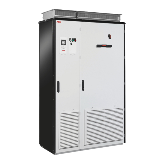
This chapter briefly describes the operation principle and construction of the drive. Operation principle The ACS880-37 is a low-harmonic, air-cooled, cabinet-installed drive for controlling asynchronous AC induction motors, permanent magnet synchronous motors, AC induction servomotors and ABB synchronous reluctance (SynRM) motors. -
Page 32: Ac Voltage And Current Waveforms
32 Operation principle and hardware description The following figure shows the simplified main circuit diagram of the supply unit. Larger drives have supply units that consist of multiple supply modules connected in parallel. The supply unit is controlled by a type BCU control unit [A51]. LCL filter Supply module AC fuses... -
Page 33: Overview Circuit Diagram Of The Drive
*Main contactor [Q2] *With drive types ACS880-37-1210A-3, -1430A-3, -1530A-5, -1450-7 and -1680-7, these items can be replaced by an air circuit breaker [Q1] by selecting option +F255. Larger drive types have an air circuit breaker as standard equipment. Drives with an air circuit breaker have AC fuses only at the input of each LCL filter. -
Page 34: Cabinet Line-Up And Layout Examples
34 Operation principle and hardware description Cabinet line-up and layout examples Frame 1×R8i + 1×R8i Cabinet line-up example Auxiliary control cubicle (ACU). Contains control electronics and customer I/O connections. See page 40. Supply and inverter module cubicle. Contains the supply module, LCL filter, inverter module and switchgear, as well as the power cable terminals. - Page 35 Operation principle and hardware description 35 Cabinet layout example Auxiliary control cubicle (ACU). See page 40. Input cable lead-throughs, PE busbar LCL filter module Input terminals (behind LCL filter module) Main switch/disconnector [Q1.1] (behind mounting plate) AC fuses (behind mounting plate) Fuse disconnectors for auxiliary voltage [F20.x] Main contactor [Q2.1] Charging fuse switch [Q3]...
-
Page 36: Frame 2×R8I + 2×R8I
36 Operation principle and hardware description Frame 2×R8i + 2×R8i Cabinet line-up example Auxiliary control cubicle (ACU). Contains control electronics and customer I/O connections. See page 40. Incoming cubicle. Contains the input terminals, switchgear and charging equipment. Supply module cubicle. Contains two R8i supply modules together with an LCL filter module. Inverter module cubicle. - Page 37 Operation principle and hardware description 37 Cabinet layout example Auxiliary control cubicle (ACU). See page 40. Input cable lead-throughs, PE busbar Input terminals Main switch-disconnector [Q1.1] Grounding/earthing switch [Q9.1] (option +F259) AC fuses Charging resistors and contactor Main contactor (behind charging equipment) Auxiliary voltage switch [Q21] Charging switch [Q3] Incoming cubicle cooling fan...
-
Page 38: Frame 3×R8I + 3×R8I (With Main Breaker)
38 Operation principle and hardware description Frame 3×R8i + 3×R8i (with main breaker) Cabinet line-up example Auxiliary control cubicle (ACU). Contains control electronics and customer I/O connections. See page 40. Incoming cubicle. Contains the input terminals, switchgear and charging equipment. Supply module cubicle (1). - Page 39 Operation principle and hardware description 39 Cabinet layout example Auxiliary control cubicle (ACU). See page 40. Input cable lead-throughs, PE busbar Input terminals Charging resistors Incoming cubicle cooling fans (behind the charging resistor mounting plate) Main breaker [Q1] Charging switch [Q3] Auxiliary voltage switch [Q21] Grounding/earthing switch [Q9.1] (option +F259) Charging contactor (behind auxiliary equipment)
-
Page 40: Auxiliary Control Cubicle (Acu) Layout
40 Operation principle and hardware description Auxiliary control cubicle (ACU) layout A layout example of the auxiliary control cubicle (ACU) is shown below. Swing-out frame closed, Swing-out frame open, detachable mounting plates in place without detachable mounting plates 17 18 Fuse-disconnectors F101. - Page 41 Operation principle and hardware description 41 Switch F90 for ground fault monitoring (item 12) 24 Motor fan starters and contactors (options +M602…610) FSO-xx safety functions module (option +Q973 25 Terminal blocks X601 for motor fan connections and other options requiring FSO-xx) (options +M602…610) Temperature monitoring relays (options +L505 26 24 V DC power supply for cabinet lighting...
-
Page 42: Overview Of Power And Control Connections
42 Operation principle and hardware description Overview of power and control connections The diagram shows the power connections and control interfaces of the drive. ACS880-37 Supply control unit [A51] Inverter control unit [A41] Slots 1, 2 and 3 Slot 4 X205 V1T/R…... - Page 43 Operation principle and hardware description 43 Fiber optic link to each inverter module. Similarly, each supply module is connected to the supply control unit by fiber optic cables. Terminal blocks for customer connections installed in the drive cabinet. For the locations, see Auxiliary control cubicle (ACU) layout (page 40).
-
Page 44: Door Switches And Lights
44 Operation principle and hardware description Door switches and lights Label in English Label in local Description language READY Ready light (option +G327) Run light (option +G328) FAULT Fault light (option +G329) RUN/ENBL Run enable signal switch for the supply unit OFF Run enable signal off (starting the supply unit not allowed) Run enable signal on... -
Page 45: Main Disconnecting Device [Q1.1]
Operation principle and hardware description 45 Main disconnecting device [Q1.1] Depending on the configuration of the drive, the main disconnecting device of the drive is either a switch-disconnector or a main circuit breaker. Units with a switch-disconnector also have a main contactor. The main disconnecting device switches the main supply to the drive on and off. -
Page 46: Control Panel
46 Operation principle and hardware description Control panel The ACS-AP-I is the user interface of the drive. It provides the essential controls such as Start/Stop/Direction/Reset/Reference, and the parameter settings for the inverter control program. One control panel can be used to control several drives through a panel link; see section Panel bus (Control of several units from one control panel) (page 119). -
Page 47: Descriptions Of Cabinet Options
Operation principle and hardware description 47 Descriptions of cabinet options Degree of protection Definitions According to IEC/EN 60529, the degree of protection is indicated by an IP code where the first numeral means protection against ingress of solid foreign objects, and the second numeral protection against ingress of water. -
Page 48: Marine Construction (Option +C121)
48 Operation principle and hardware description Marine construction (option +C121) The option includes the following accessories and features: • reinforced mechanics • grab railings • door flush bolt which allows the door to open 90 degrees and prevents it from slamming close •... -
Page 49: Cabinet Heater With External Supply (Option +G300)
Operation principle and hardware description 49 Cabinet heater with external supply (option +G300) The option contains: • heating elements in the cubicles and supply/inverter modules • load switch for providing electrical isolation during service • miniature circuit breaker for overcurrent protection •... -
Page 50: Additional Wire Markings (Options +G340 And +G342)
50 Operation principle and hardware description Additional wire markings (options +G340 and +G342) As standard, drive input and output terminals, plug-in connectors, fiber optic connectors and ribbon cables are marked. The wire marking options are described below. Additional markings +G340 Equipment pin numbers are marked with snap-on markers on wires between modules and on wires connected to equipment, terminal blocks and detachable screw terminals. -
Page 51: Additional Terminal Block X504 (Option +L504)
Operation principle and hardware description 51 WARNING! The bridging can carry the nominal output of one inverter module. In case of three parallel modules, ensure that the load capacity of the bridging is not exceeded. For example, if the cabling connects to the output busbars at one module only, use the module in the middle. -
Page 52: Pt100 Relays (Options +2L506, +3L506, +5L506, +8L506)
52 Operation principle and hardware description The customer connects PTC sensors to the thermistor relay, and the terminals of the auxiliary relay of the normally open contact, for example, to • main breaker control circuit of the drive for opening the breaker in case of motor overtemperature or •... -
Page 53: Type Designation Label
Type designation key The type designation contains information on the specifications and configuration of the drive. The first digits from left express the basic configuration (eg, ACS880-37-1210A-3). The optional selections are given thereafter, separated by plus signs, eg, +E202. The main selections are described below. - Page 54 54 Operation principle and hardware description CODE DESCRIPTION Option codes (plus codes) Degree of protection B054 IP42 (UL Type 1 Filtered) B055 IP54 (UL Type 12) Construction C121 Marine construction (reinforced mechanics and fastening, handrails, self-extinctive materials) C129 UL Listed (US type main switch fuse, top entry and exit of cables, cable conduit entries, all components UL Listed or Recognized, max.
- Page 55 Operation principle and hardware description 55 CODE DESCRIPTION H366 Common output terminals (for inverter modules mounted in the same cubicle) Fieldbus adapters K451 FDNA-01 DeviceNet™ adapter module K452 FLON-01 LonWorks® adapter module K454 FPBA-01 PROFIBUS DP adapter module K457 FCAN-01 CANopen adapter module K458 FSCA-01 RS-485 adapter module K462...
- Page 56 56 Operation principle and hardware description CODE DESCRIPTION Safety functions Q950 Prevention of unexpected start-up with FSO-xx safety functions module, by activating the Safe torque off function Q951 Emergency stop (category 0) with safety relays, by opening the main breaker/contactor Q952 Emergency stop (category 1) with safety relays, by opening the main breaker/contactor Q954...
-
Page 57: Contents Of This Chapter
Mechanical installation 57 Mechanical installation Contents of this chapter This chapter describes the mechanical installation procedure of the drive. Examining the installation site Examine the installation site: • The installation site is sufficiently ventilated or cooled to transfer away the drive losses. -
Page 58: Necessary Tools
58 Mechanical installation Note: Try to avoid installing the drive on an elevated platform or a recess. The module extraction/installation ramp supplied with the drive can only be used on a level floor. Necessary tools The tools required for moving the unit to its final position, fastening it to the floor and wall and tightening the connections are listed below: •... -
Page 59: Moving And Unpacking The Drive
Mechanical installation 59 Moving and unpacking the drive Move the drive in its original packaging to the installation site as shown below to avoid damaging the cabinet surfaces and door devices. When you are using a pallet truck, check its load capacity before you move the drive. The drive cabinet is to be moved in the upright position. -
Page 60: Lifting The Crate With A Crane
60 Mechanical installation Lifting the crate with a crane Position each sling as close to a transverse board as possible. We recommend the use of transverse spreader bars. Lifting point... -
Page 61: Moving The Crate With A Forklift
Mechanical installation 61 Moving the crate with a forklift Free width for fork tines: 750 mm (29.5”) -
Page 62: Removing The Transport Package
62 Mechanical installation Removing the transport package Remove the transport package as follows: 1. Undo the screws that attach the wooden parts of the transport crate together. 2. Remove the wooden parts. 3. Remove the clamps with which the drive cabinet is mounted onto the transport pallet by undoing the fastening screws. -
Page 63: Moving The Cabinet On Rollers
Mechanical installation 63 Moving the cabinet on rollers WARNING: Do not move marine versions (option +C121) on rollers. Lay the cabinet on the rollers and move it carefully until close to its final location. Remove the rollers by lifting the unit with a crane, forklift, pallet truck or jack. Moving the cabinet on its back WARNING: Transportation of the cabinet on its back is only allowed with the BLCL (LCL filter) modules and sine filters (option +E206) removed from the... -
Page 64: Final Placement Of The Cabinet
64 Mechanical installation Final placement of the cabinet Move the cabinet into its final position with a slate bar (spud bar). Place a piece of wood between the edge of the cabinet and the bar to protect the cabinet frame. -
Page 65: Fastening The Cabinet To The Floor And Wall Or Roof (Non-Marine Units)
Mechanical installation 65 Fastening the cabinet to the floor and wall or roof (non- marine units) General rules • The drive must be installed in an upright vertical position. • The cabinet can be installed with its back against a wall (a), or back-to-back with another unit (b). -
Page 66: Fastening Methods
66 Mechanical installation Fastening methods Fasten the cabinet to the floor by using clamps along the edge of the cabinet bottom, or by bolting the cabinet to the floor through the holes inside (if they are accessible). Alternative 1 – Clamping ... -
Page 67: Fastening The Cabinet To The Floor And Roof/Wall (Marine Units)
Mechanical installation 67 Fastening the cabinet to the floor and roof/wall (marine units) Follow the general rules given in section General rules on page 65. See the dimension drawing delivered with the drive for the locations of the fastening holes in the flat bars below the cabinet and for fastening points at the top of the cabinet. -
Page 68: Miscellaneous
68 Mechanical installation Miscellaneous Cable duct in the floor below the cabinet A cable duct can be constructed below the 500 mm wide middle part of the cabinet. The cabinet weight lies on the two 50 mm wide transverse sections which the floor must carry. Prevent the cooling air flow from the cable duct to the cabinet by bottom plates. -
Page 69: Calculating The Required Static Pressure Difference
= 17 Pa The required pressure in the exit air duct is then, 1.5…2 • 17 Pa = 26…34 Pa, below the pressure in the room. For more information: Contact ABB. Arc welding Fastening the cabinet by arc welding is not recommended. However, if arc welding is the only mounting option, connect the return conductor of the welding equipment to the cabinet frame at the bottom within 0.5 meters (1’6”) of the welding point. - Page 70 70 Mechanical installation...
-
Page 71: Contents Of This Chapter
ABB does not assume any liability whatsoever for any installation which breaches the local laws and/or other regulations. Furthermore, if the recommendations given by ABB are not followed, the drive may experience problems that the warranty does not cover. -
Page 72: Examining The Compatibility Of The Motor And Drive
72 Guidelines for planning the electrical installation Examining the compatibility of the motor and drive Use an asynchronous AC induction motor, permanent magnet synchronous motor or AC induction servomotor with the drive. Several induction motors can be connected to the drive at a time. -
Page 73: Requirements Table
Motor Nominal AC Requirement for type supply voltage Motor ABB du/dt and common mode filters, insulated N-end insulation motor bearings system < 100 kW 100 kW < P < 350 kW > 350 kW and frame size <... -
Page 74: Additional Requirements For Explosion-Safe (Ex) Motors
74 Guidelines for planning the electrical installation Motor Nominal AC Requirement for type supply voltage Motor ABB du/dt and common mode filters, insulated N-end insulation motor bearings system < 100 kW 100 kW < P < 350 kW > 350 kW and frame size <... -
Page 75: Additional Requirements For Braking Applications
Additional requirements for non-ABB high-output and IP23 motors The rated output power of high-output motors is higher than what is stated for the particular frame size in EN 50347 (2001). If you plan to use a non-ABB high-output motor or an IP23 motor, consult the motor manufacturer. -
Page 76: Additional Data For Calculating The Rise Time And The Peak Line-To-Line Voltage
76 Guidelines for planning the electrical installation Additional data for calculating the rise time and the peak line-to-line voltage If you need to calculate the actual peak voltage and voltage rise time considering the actual cable length, proceed as follows: •... - Page 77 Guidelines for planning the electrical installation 77 Note: When continuous metal conduit is employed, shielded cable is not required. The conduit must have bonding at both ends. A four-conductor system is allowed for input cabling, but shielded symmetrical cable is recommended.
-
Page 78: Typical Cable Sizes
For drawings of the terminals, see chapter Dimensions (page 191). Drive type Al cable size Cu cable size Cu cable size ACS880-37-… AWG/kcmil = 400 V 0450A-3 2 × (3 × 240 + 72 Cu) 2 × (3 × 150 + 70) 0620A-3 3 ×... -
Page 79: Output (Motor) Cable Sizes
Common output terminal (option +H366) (page 50). Drive type Al cable size Cu cable size Cu cable size ACS880-37-… AWG/kcmil = 400 V 0450A-3 2 × (3 × 240 + 72 Cu) 2 × (3 × 185 + 95) 0620A-3 4 ×... -
Page 80: Alternative Power Cable Types
80 Guidelines for planning the electrical installation on top of the other, ambient temperature 30 °C, PVC insulation, surface temperature 70 °C (EN 60204-1 and IEC 60364-5-52/2001). For other conditions, size the cables according to local safety regulations, appropriate input voltage and the load current of the drive. 2. -
Page 81: Additional Us Requirements
Guidelines for planning the electrical installation 81 concentric layer of copper wires with an open helix of copper tape or copper wire. The better and tighter the shield, the lower the emission level and bearing currents. Insulation jacket Copper wire screen Helix of copper tape or copper wire Inner insulation Cable core... -
Page 82: Signals In Separate Cables
Relay cable type The cable type with braided metallic screen (for example ÖLFLEX by LAPPKABEL, Germany) has been tested and approved by ABB. Control panel cable length and type In remote use, the cable connecting the control panel to the drive must not be longer than three meters (10 ft). -
Page 83: Separate Control Cable Ducts
Guidelines for planning the electrical installation 83 A diagram of the cable routing is shown below. Motor cable Drive min 300 mm (12 in.) Power cable Input power cable Motor cable 90 ° min 200 mm (8 in.) min 500 mm (20 in.) Control cables Separate control cable ducts ... -
Page 84: Implementing Thermal Overload And Short-Circuit Protection
84 Guidelines for planning the electrical installation Implementing thermal overload and short-circuit protection Protecting the drive and input power cable in short-circuits The drive is equipped with internal AC fuses as standard. Protect the input cable with fuses or a suitable circuit breaker. Size the input cable fuses according to the instructions given in chapter Technical data. -
Page 85: Residual Current Device Compatibility
Guidelines for planning the electrical installation 85 Residual current device compatibility The drive is suitable to be used with residual current devices of Type B. Note: The EMC filter of the drive includes capacitors connected between the main circuit and the frame. -
Page 86: Declaration Of Conformity
86 Guidelines for planning the electrical installation Implementing the functions provided by the FSO-xx safety functions module (option +Q972 or +Q973) The drive can be equipped with an FSO-xx safety functions module (option +Q972 or +Q973) which enables the implementation of functions such as Safe brake control (SBC), Safe stop 1 (SS1), Safe stop emergency (SSE), Safely limited speed (SLS) and Safe maximum speed (SMS). -
Page 87: Using Power Factor Compensation Capacitors With The Drive
Guidelines for planning the electrical installation 87 Using power factor compensation capacitors with the drive Power factor compensation is not needed with AC drives. However, if a drive is to be connected in a system with compensation capacitors installed, note the following restrictions. -
Page 88: Connecting A Motor Temperature Sensor To The Drive I/O
88 Guidelines for planning the electrical installation 230 V AC 230 V AC + 24 V DC 1) Relay outputs; 2) Varistor; 3) RC filter; 4) diode Connecting a motor temperature sensor to the drive I/O WARNING! IEC 60664 requires double or reinforced insulation between live parts and the surface of accessible parts of electrical equipment which are either non- conductive or conductive but not connected to the protective earth. -
Page 89: Contents Of This Chapter
Electrical installation 89 Electrical installation Contents of this chapter This chapter gives instructions on the wiring the drive. Warnings WARNING! Only qualified electricians are allowed to carry out the work described in this chapter. Follow the Safety instructions on the first pages of this manual. Ignoring the safety instructions can cause injury or death. -
Page 90: Motor And Motor Cable
Earth conductor using a measuring voltage of 1000 V DC. The insulation resistance of an ABB motor must exceed 100 Mohm (reference value at 25 °C or 77 °F). For the insulation resistance of other motors, consult the manufacturer’s instructions. Note: Moisture inside the motor casing will reduce the insulation resistance. -
Page 91: T21 And T101 Tap Settings (400...500 V Units)
Electrical installation 91 T21 and T101 tap settings (400…500 V units) T21_X2 or T101_X2 T21_X1 or T101_X1 500 V 230 V 480 V 460 V 440 V 415 V Θ 400 V 380 V T21 and T101 tap settings (690 V units) ... -
Page 92: T111 Tap Settings
92 Electrical installation T111 tap settings 3~ input 3~ output 3~ input 3~ output Tap settings Terminals Supply Terminals 400 V 320/340 V voltage A1– B1– C1– (50 Hz) (60 Hz) 690 V A1, B1, C1 a1, b1, c1 a2, b2, c2 660 V A1, B1, C1... -
Page 93: Connecting The Control Cables
Electrical installation 93 Connecting the control cables See chapter Control units of the drive (page 123) for the default I/O connections of the inverter unit (with the ACS880 primary control program). The default I/O connections can be different with some hardware options, see the circuit diagrams delivered with the drive for the actual wiring. - Page 94 94 Electrical installation Note 1: Keep the shields continuous as close to the connection terminals as possible. Secure the cables mechanically at the lead-through strain relief. Note 2: If the outer surface of the shield is non-conductive: • Cut the shield at the midpoint of the bare part. Be careful not to cut the conductors or the grounding wire (if present).
-
Page 95: Routing The Control Cables Inside The Cabinet
Electrical installation 95 5. Arrange the bunches according to size from thickest to the thinnest between the EMI conductive cushions. 6. If more than one cable go through a grommet, seal the grommet by applying Loctite 5221 (catalogue number 25551) inside the grommet. Routing the control cables inside the cabinet Use the existing trunking in the cabinet wherever possible. - Page 96 96 Electrical installation At the other end of the cable, leave the shields unconnected or ground them indirectly via a high-frequency capacitor with a few nanofarads, eg. 3.3 nF / 630 V. The shield can also be grounded directly at both ends if they are in the same ground line with no significant voltage drop between the end points.
-
Page 97: Connecting An Auxiliary Voltage Supply (Ups, Option +G307)
Electrical installation 97 Connecting an auxiliary voltage supply (UPS, option +G307) Wire the external control voltage to terminal block X307 at the back side of the mounting plate as shown below. X307 Internal wiring of UPS supervision: circuit breaker or fuse off/fault = contact open. Connecting emergency stop push buttons (options +Q951, +Q952, +Q963, +Q964, +Q978, +Q979) Connect external emergency stop push buttons according to the circuit diagrams delivered... -
Page 98: Wiring The Thermistor Relay(S) (Options +L505 And +2L505)
98 Electrical installation Wiring the thermistor relay(s) (options +L505 and +2L505) The external wiring of option +2L505 (two thermistor relays) is shown below. For example, one relay can be used to monitor the motor windings, the other to monitor the bearings. The maximum contact load capacity is 250 V AC 10 A. -
Page 99: Wiring The Pt100 Relays (Options +2L506, +3L506, +5L506 And +8L506)
Electrical installation 99 Wiring the Pt100 relays (options +2L506, +3L506, +5L506 and +8L506) External wiring of eight Pt100 sensor modules is shown below. Contact load capacity 250 V AC 10 A. For the actual wiring, see the circuit diagram delivered with the drive. X506 1 ×... -
Page 100: Powering The Heating And Lighting Equipment (Options +G300, +G301 And +G313
100 Electrical installation Powering the heating and lighting equipment (options +G300, +G301 and +G313) See the circuit diagrams delivered with drive. Connect the external power supply wires for the cabinet heater and lighting to terminal block X300 at the back of the mounting plate. X300 Internal wiring of the cabinet heater: heater off/fault = contact open. -
Page 101: Wiring Ground Fault Monitoring For It Ungrounded Systems (Option +Q954)
Electrical installation 101 Wiring ground fault monitoring for IT ungrounded systems (option +Q954) We recommend to connect Alarm 1 for drive tripping and Alarm 2 for alarm signals in order to avoid unnecessary trippings due to the ground fault monitor self testing with Alarm 2. X954 Internal wiring: Ground fault alarm 1. -
Page 102: Connecting The Motor Cables (Units Without Common Motor Terminal Cubicle)
102 Electrical installation Connecting the motor cables (units without common motor terminal cubicle) If the drive is equipped with a common motor terminal cubicle (option +H359), follow the procedure starting on page 113. Output busbars The motor cables are to be connected to the output busbars behind each inverter module. The location and dimensions of the busbars are visible in the dimensional drawings delivered with the drive, as well as the example drawings presented in this manual (starting on page 214). -
Page 103: Connection Diagram (With Option +H366)
Electrical installation 103 Connection diagram (with option +H366) With option +H366, the output busbars of the inverter modules within the same cubicle are connected by bridging busbars. The bridging balances the motor current between the modules, which allows more cabling options. For example, it is possible to use a number of cables that could not otherwise be evenly distributed between the inverter modules. -
Page 104: Procedure
104 Electrical installation Procedure The procedure involves removing the fan carriage of each inverter module, making the connections, and reinserting the fan carriage. To allow more room for making the connections, the inverter module can be removed completely instead of just the fan carriage. To do this, follow the procedure under Removing the inverter module (page 106). - Page 105 Electrical installation 105...
-
Page 106: Removing The Inverter Module
106 Electrical installation Removing the inverter module To allow more room for cabling work, the inverter module can be removed completely instead of only the fan carriage. Refer to the drawings below. WARNING! Obey the instructions in chapter Safety instructions. If you ignore them, injury or death, or damage to the equipment can occur. - Page 107 Electrical installation 107...
- Page 108 108 Electrical installation...
- Page 109 Electrical installation 109...
-
Page 110: Connecting The Motor Cables
110 Electrical installation Connecting the motor cables Refer to the drawings below. WARNING! Obey the instructions in chapter Safety instructions. If you ignore them, injury or death, or damage to the equipment can occur. 1. Do the steps in section Precautions before electrical work (page 21) before you start the work. - Page 111 Electrical installation 111 360° grounding detail b > 1/5 · a...
-
Page 112: Re-Inserting The Fan Carriage Of An Inverter Module
112 Electrical installation Re-inserting the fan carriage of an inverter module (If the inverter module was removed completely instead of only the fan carriage, proceed to section Re-inserting the inverter module into the cubicle below.) The re-installation of the fan carriage is the removal procedure in reverse. See section Removing and reinstalling the fan carriage of an inverter module (page 104). -
Page 113: Connecting The Motor Cables (Units With Common Motor Terminal Cubicle)
Electrical installation 113 Connecting the motor cables (units with common motor terminal cubicle) Output busbars If the drive is equipped with option +H359, the motor is connected to a common motor terminal cubicle. The location and dimensions of the busbars are visible in the dimensional drawings delivered with the drive, as well as the drawings starting on page 218. -
Page 114: Connecting An External Brake Resistor Assembly
114 Electrical installation 4. Cut the cables to suitable length. Strip the cables and conductors. 5. Twist the cable screens into bundles and connect the bundles to the PE busbar in the cubicle. 6. Connect any separate ground conductors/cables to the PE busbar in the cubicle. 7. -
Page 115: Connecting The Input Power Cables
Electrical installation 115 Connecting the input power cables Connection diagram LCL filter IGBT supply modules Components for charging circuit ICU cubicle ISU cubicle Notes: Fuses or other protection means. Use a separate PE conductor in addition if the conductivity of the shield does not meet the requirement for the PE conductor. - Page 116 10. Fasten the conductive sleeves to the cable shields with cable ties. 11. Seal the slot between the cable and mineral wool sheet (if used) with sealing compound (eg, CSD-F, ABB brand name DXXT-11, code 35080082). 12. Tie up the unused conductive sleeves with cable ties.
- Page 117 Electrical installation 117...
-
Page 118: Connecting A Pc
118 Electrical installation Connecting a PC A PC (with eg. the Drive composer PC tool) can be connected to the inverter unit as follows: 1. Connect an ACS-AP-I control panel to the inverter control unit either by using an Ethernet (eg. CAT5E) networking cable, or by inserting the panel into the panel holder (if present). -
Page 119: Panel Bus (Control Of Several Units From One Control Panel)
Electrical installation 119 Panel bus (Control of several units from one control panel) One control panel (or PC) can be used to control several supply or inverter units by constructing a panel bus. A control panel mounting platform or an FDPI-02 module is required. -
Page 120: Installing Option Modules
120 Electrical installation Installing option modules Mechanical installation of I/O extension, fieldbus adapter and pulse encoder interface modules See page for the available slots for each module. Install the option modules as follows: WARNING! Obey the instructions in chapter Safety instructions. -
Page 121: Mechanical Installation Of An Fso-Xx Safety Functions Module
Electrical installation 121 Mechanical installation of an FSO-xx safety functions module 1. Fasten the FSO-xx safety functions module onto slot 3 of the inverter control unit [A41] with four screws. 2. Tighten the FSO-xx electronics grounding screw. 3. Connect the FSO-xx data cable between FSO-xx connector X110 and to BCU-x2 connector X12. -
Page 122: Wiring Of Option Modules
122 Electrical installation Wiring of option modules See the appropriate option module manual for specific installation and wiring instructions. -
Page 123: What This Chapter Contains
(and a BIOC-01 I/O connector board and power supply board) built in a metal housing. The supply and inverter units of the ACS880-37 are each controlled by a dedicated BCU-x2 control unit. The designation of the supply control unit is A51; the inverter control unit is A41. -
Page 124: Control Unit Layout And Connections
124 Control units of the drive Control unit layout and connections Description I/O terminals (see following diagram) SLOT 1 I/O extension, encoder interface or fieldbus adapter module connection. (This is the sole location for an FDPI-02 diagnostics and panel interface.) SLOT 2 I/O extension, encoder interface or fieldbus adapter module connection... - Page 125 Control units of the drive 125 Description Analog inputs Analog outputs Digital inputs, Digital input interlock (DIIL) XRO3 XDIO Digital input/outputs XD24 XPOW XD2D Drive-to-drive link XD24 +24 V output (for digital inputs) XRO2 XETH Ethernet port (eg. for PC communication) XDIO XPOW External power input...
- Page 126 126 Control units of the drive Default I/O diagram of the supply control unit [A51] The diagram below shows the default I/O connections on the supply control unit [A51], and describes the use of the signals/connections in the supply unit. Under normal circumstances, the factory-made wiring should not be changed.
-
Page 127: Default I/O Diagram Of The Inverter Control Unit [A41]
Control units of the drive 127 Default I/O diagram of the inverter control unit [A41] Drive-to-drive link XD2D Drive-to-drive link BGND Shield RS485 connection X485 Not in use BGND Shield Relay outputs XRO1…XRO3 Ready 250 V AC / 30 V DC Running 250 V AC / 30 V DC Fault... -
Page 128: External Power Supply For The Control Unit (Xpow)
128 Control units of the drive Notes: The wire size accepted by all screw terminals (for both stranded and solid wire) is 0.5 … 2.5 mm (24…12 AWG). The torque is 0.5 N·m (5 lbf·in). See section Drive-to-drive link (page 129). See chapter The Safe torque off function (page 223). -
Page 129: Ai1 Or Ai2 As A Pt100 Or Kty84 Sensor Input
Control units of the drive 129 and must not be connected to other equipment or the temperature sensor must be isolated from the I/O terminals. AI1 or AI2 as a Pt100 or KTY84 sensor input Three Pt100 sensors or one KTY84 sensor for motor temperature measurement can be connected between an analog input and output as shown below. -
Page 130: Safe Torque Off
The BCU-x2 has an on-board data logger that collects real-time data from the inverter module power stages to help fault tracing and analysis. The data is stored onto the SDHC memory card inserted into the SD CARD slot and can be analyzed by ABB service personnel. -
Page 131: Control Unit Connector Data
Control units of the drive 131 Control unit connector data Power supply Connector pitch 5 mm, wire size 2.5 mm (XPOW) 24 V (±10%) DC, 2 A External power input. Two supplies can be connected for redundancy. Relay outputs RO1…RO3 Connector pitch 5 mm, wire size 2.5 mm (XRO1…XRO3) 250 V AC / 30 V DC, 2 A... - Page 132 132 Control units of the drive Analog outputs AO1 and AO2 Connector pitch 5 mm, wire size 2.5 mm (XAO) 0…20 mA, R < 500 ohm load Frequency range: 0…500 Hz Resolution: 11 bit + sign bit Inaccuracy: 2% of full scale range Drive-to-drive link Connector pitch 5 mm, wire size 2.5 mm (XD2D)
- Page 133 Control units of the drive 133 Ground isolation diagram XPOW +24VI +24VI +VREF -VREF AGND AI1+ Common mode voltage between AI1- each AI input and AGND is AI2+ +30 V AI2- AGND AGND XD2D BGND SHIELD XRO1, XRO2, XRO3 XD24 *Ground selector (DICOM = DIOGND) +24VD settings...
- Page 134 134 Control units of the drive...
-
Page 135: Contents Of This Chapter
Installation checklist 135 Installation checklist Contents of this chapter This chapter contains an installation checklist which you must complete before you start up the drive. Warnings WARNING! Obey the instructions in chapter Safety instructions. If you ignore them, injury or death, or damage to the equipment can occur. Checklist Do the steps in section Precautions before electrical work... - Page 136 136 Installation checklist Check that … There is an adequately sized protective earth (ground) conductor between the drive and the switchboard, and the conductor has been connected to appropriate terminal. Proper grounding has also been measured according to the regulations. There is an adequately sized protective earth (ground) conductor between the motor and the drive, and the conductor has been connected to appropriate terminal.
-
Page 137: Contents Of This Chapter
Start-up 137 Start-up Contents of this chapter This chapter contains the start-up procedure of the drive. Start-up procedure The tasks which are needed in certain cases only are marked with underlining, and option codes are given in brackets. Default device designations (if any) are given in brackets after the name, for example “main switch-disconnector [Q1]”. -
Page 138: Checks/Settings With No Voltage Connected
138 Start-up Action Safety WARNING! Obey the safety instructions during the start-up procedure. See chapter Safety instructions on page Checks/Settings with no voltage connected Ensure that the disconnector of the supply transformer is locked to the off (0) position, ie. no voltage is, and cannot be connected to the drive inadvertently. -
Page 139: Setting Up The Supply Unit Parameters
Start-up 139 Action Switch on the auxiliary voltage [Q21]. Drives of frame size 1×R8i + 1×R8i: Close the main switch-disconnector [Q1.1]. This will power up the main circuit of the drive as well as the auxiliary voltage circuit. Setting up the supply unit parameters Check the voltage range setting in parameter 195.01 Supply voltage. - Page 140 140 Start-up...
-
Page 141: Contents Of This Chapter
Fault tracing 141 Fault tracing Contents of this chapter This chapter describes the fault tracing possibilities of the drive. LEDs Where Color Indication Control POWER Green Control unit is powered and +15 V is supplied to the control panel panel. mounting FAULT Drive in fault state. - Page 142 142 Fault tracing...
-
Page 143: Contents Of This Chapter
The recommended maintenance intervals and component replacements are based on specified operational and environmental conditions. Maintain the drive according to the recommended maintenance intervals. Consult your local ABB Service representative for more details on the maintenance. On the Internet, go to http://www.abb.com/drivesservices. - Page 144 144 Maintenance Years from start-up Component … Module internal cooling fan for circuit boards Aging Control panel battery, BCU control unit batteries Connections and environment IP22 and IP42 air inlet (door) meshes IP54 air inlet (door) filters Tightness of terminals Dustiness, corrosion and temperature Supply module heat sink...
-
Page 145: Cabinet
Maintenance 145 Cabinet Cleaning the interior of the cabinet WARNING! Obey the instructions in chapter Safety instructions. If you ignore them, injury or death, or damage to the equipment can occur. WARNING! Use a vacuum cleaner with an antistatic hose and nozzle, and wear a grounding wristband. -
Page 146: Cleaning The Door Air Inlets (Ip54)
146 Maintenance Cleaning the door air inlets (IP54) 1. Remove the fasteners at the top of the grating. 2. Lift the grating and pull it away from the door. 3. Remove the air filter mat. 4. Place the new filter mat in the grating the metal wire side facing the door. 5. -
Page 147: Heatsink
Maintenance 147 Heatsink The drive module heatsink fins pick up dust from the cooling air. The drive runs into overtemperature warnings and faults if the heatsink is not clean. When necessary, clean the heatsink as follows. WARNING! Obey the instructions in chapter Safety instructions. -
Page 148: Power Connections And Quick Connectors
148 Maintenance Power connections and quick connectors Retightening the power connections WARNING! Obey the instructions in chapter Safety instructions. If you ignore them, injury or death, or damage to the equipment can occur. 1. Stop the drive (if running) and do the steps in section Precautions before electrical work (page 21) before you start the work. -
Page 149: Fans
Reset the running time signal after a fan replacement. Replacement fans are available from ABB. Do not use other than ABB specified spare parts. Replacing the cooling fan in the auxiliary control cubicle ... -
Page 150: Replacing The Fan(S) In The Incoming Cubicle
150 Maintenance Replacing the fan(s) in the incoming cubicle WARNING! Obey the instructions in chapter Safety instructions. If you ignore them, injury or death, or damage to the equipment can occur. 1. Stop the drive and do the steps in section Precautions before electrical work (page 21) before you start the work. -
Page 151: Replacing A Roof Fan (Ip54)
Maintenance 151 Replacing a roof fan (IP54) WARNING! Obey the instructions in chapter Safety instructions. If you ignore them, injury or death, or damage to the equipment can occur. 1. Stop the drive and do the steps in section Precautions before electrical work (page 21) before you start the work. -
Page 152: Replacing A Supply Or Inverter Module Cooling Fan (Speed-Controlled Version)
152 Maintenance Replacing a supply or inverter module cooling fan (speed- controlled version) If the drive is equipped with direct-on-line power module cooling fans (option +C188), see page 153. WARNING! Obey the instructions in chapter Safety instructions. If you ignore them, injury or death, or damage to the equipment can occur. - Page 153 Maintenance 153 Replacing a supply or inverter module cooling fan, direct-on-line version (option +C188) WARNING! Obey the instructions in chapter Safety instructions. If you ignore them, injury or death, or damage to the equipment can occur. 1. Stop the drive (if running) and do the steps in section Precautions before electrical work (page 21) before you start the work.
- Page 154 154 Maintenance...
-
Page 155: Replacing The Circuit Board Compartment Fan (Frame R8I)
Maintenance 155 Replacing the circuit board compartment fan (frame R8i) The R8i module is equipped with a fan blowing air through the circuit board compartment. The fan is accessible from the front of the module. WARNING! Obey the instructions in chapter Safety instructions. - Page 156 156 Maintenance 8. Put the fan onto the threaded studs on the fan holder with the airflow direction arrow pointing towards the fan holder. 9. Install and tighten the four nuts removed earlier. 10. Connect the fan cable. 11. Align and push the fan holder into the module. 12.
-
Page 157: Replacing The Fan Of The Lcl Filter (Blcl-1X-X)
Maintenance 157 Replacing the fan of the LCL filter (BLCL-1x-x) WARNING! Obey the instructions in chapter Safety instructions. If you ignore them, injury or death, or damage to the equipment can occur. 1. Stop the drive (if running) and do the steps in section Precautions before electrical work (page 21) before you start the work. -
Page 158: Replacing The Fan Of The Lcl Filter (Blcl-2X-X)
158 Maintenance Replacing the fan of the LCL filter (BLCL-2x-x) WARNING! Obey the instructions in chapter Safety instructions. If you ignore them, injury or death, or damage to the equipment can occur. 1. Stop the drive (if running) and do the steps in section Precautions before electrical work (page 21) before you start the work. -
Page 159: Supply And Inverter Modules
Maintenance 159 Supply and inverter modules Cleaning The module heatsink fins pick up dust from the cooling air. The module runs into overtemperature warnings and faults if the heatsink is not clean. In a “normal” environment (neither especially dusty nor clean), the heatsink should be checked annually, in a dusty environment more often. -
Page 160: Lcl Filter
160 Maintenance LCL filter Replacing the LCL filter WARNING! Ignoring the following instructions can cause physical injury, or damage to the equipment: • Use extreme caution when maneuvering modules that run on wheels. The modules are heavy and have a high center of gravity. They topple over easily if handled carelessly. - Page 161 Maintenance 161 11. Pull the module carefully out of the cabinet along the ramp. While pulling on the handle, keep a constant pressure with one foot on the base of the module to prevent the module from falling on its back. 12.
- Page 162 162 Maintenance...
- Page 163 Maintenance 163...
-
Page 164: Capacitors
Capacitor failure is usually followed by damage to the unit and an input cable fuse failure, or a fault trip. Contact ABB if capacitor failure is suspected. Replacements are available from ABB. Do not use other than ABB-specified spare parts. -
Page 165: Fuses
Maintenance 165 Fuses Replacing the AC fuses in the incoming cubicle Units without a main breaker have AC fuses in the incoming cubicle (or, in the case of frame 1×R8i + 1×R8i, in the combined supply and inverter module cubicle). WARNING! Obey the instructions in chapter Safety instructions. - Page 166 166 Maintenance Replacing the DC fuses in the supply module cubicle (frame 2×R8i + 2×R8i and up) There are DC fuses at the output of each supply module (labeled 4b in the drawing below). Note that there are also DC fuses at the input of each inverter module; see page 168. This procedure can also be used to replace the AC fuses located above the LCL filter modules (4a).
- Page 167 Maintenance 167...
- Page 168 168 Maintenance Replacing the DC fuses in the inverter module cubicle (frame 2×R8i + 2×R8i and up) Parallel-connected inverter modules have DC fuses fitted above each module. WARNING! Obey the instructions in chapter Safety instructions. If you ignore them, injury or death, or damage to the equipment can occur. 1.
-
Page 169: Control Panel
Maintenance 169 Control panel Replacing the battery 1. Turn the lid on the back of the panel counter-clockwise until the lid opens. 2. Replace the battery with a new CR2032 battery. 3. Put the lid back and tighten it by turning it clockwise. 4. -
Page 170: Memory Unit
170 Maintenance Memory unit After replacing a supply or inverter control unit, the existing parameter settings can be retained by transferring the memory unit from the defective control unit to the new control unit. WARNING! Do not remove or insert the memory unit when the control unit is powered. -
Page 171: Contents Of This Chapter
The nominal ratings for the drives with 50 Hz and 60 Hz supply are given below. The symbols are described below the table. Output ratings Nominal ratings Light-overload Heavy-duty use Drive type = 400 V ACS880-37-0450A-3 ACS880-37-0620A-3 ACS880-37-0870A-3 1140 ACS880-37-1110A-3 1110 1450 1066... -
Page 172: Definitions
Note 2: To achieve the rated motor power given in the table, the rated current of the drive must be higher than or equal to the rated motor current. The DriveSize dimensioning tool available from ABB is recommended for selecting the drive, motor and gear combination. -
Page 173: Derating
1% for every 100 m (328 ft). For a more accurate derating, use the DriveSize PC tool. Switching frequency derating Switching frequencies other than default can require output current derating. Contact ABB for more information. Output frequency derating Motor operation above 150 Hz can require type-specific output current derating. -
Page 174: Frame Sizes And Power Module Types
174 Technical data Frame sizes and power module types Supply module(s) LCL filter(s) used Inverter modules used Drive type used Frame size ACS880-37-… Type Type Type ACS880-104-… ACS880-104-… = 400 V 0450A-3 1×R8i + 1×R8i 0470A-3 BLCL-13-5 0470A-3+E205 0620A-3 1×R8i + 1×R8i... -
Page 175: Fuses
Fuses from other manufacturers can be used if they meet the ratings and the melting curve of the fuse does not exceed the melting curve of the fuse mentioned in the table. Ultrarapid (aR) AC fuses Input Drive type current ACS880-37-… Manufacturer Type at 660 V = 400 V 0450A-3... -
Page 176: Dc Fuses
Fuses from other manufacturers can be used if they meet the ratings and the melting curve of the fuse does not exceed the melting curve of the fuse mentioned in the table. DC fuses at supply module output and inverter module input Drive type ACS880-37-… Manufacturer Type = 400 V... -
Page 177: Fuses On Cvar Varistor Board
Technical data 177 Fuses on CVAR varistor board The CVAR board is used in units for UL and CSA installations. The fuse type is Ferraz A070GRB10T13/G330010 (10 A 700 V AC). Dimensions and weights See chapter Dimensions (page 191). Free space requirements Front Side... -
Page 178: Cooling Data, Noise
178 Technical data Cooling data, noise Air flow Heat dissipation Noise Drive type dB(A) /min = 400 V ACS880-37-0450A-3 2860 1680 ACS880-37-0620A-3 2860 1680 ACS880-37-0870A-3 2860 1680 ACS880-37-1110A-3 5720 3370 ACS880-37-1210A-3 5720 3370 ACS880-37-1430A-3 5720 3370 ACS880-37-1700A-3 5720 3370 ACS880-37-2060A-3... -
Page 179: Sine Output Filter Data
Technical data 179 Sine output filter data Sine output filters are available as option +E206. The table below shows the types and technical data of the filters and filter cubicles used in ACS880-37 drives. Sine filter(s) used Cooling data Dimensions... -
Page 180: Electrical Power Network Specification
*Other loads may influence the THD value. Motor connection data Motor types Asynchronous AC induction motors, permanent magnet synchronous motors, AC induction servomotors, ABB synchronous reluctance (SynRM) motors Voltage (U 0 to U , 3-phase symmetrical, U at the field weakening point... -
Page 181: Control Unit Connection Data
Technical data 181 Frequency 0…±500 Hz (0…±120 Hz with sine output filters [option +E206]) • For higher operational output frequencies, please contact your local ABB representative. • Operation above 150 Hz may require type-specific derating. For more information, contact your local ABB representative. -
Page 182: Materials
182 Technical data Contamination IEC/EN 60721-3-3:2002: IEC 60721-3-1 IEC 60721-3-2 Classification of environmental conditions - Part 3-3: Classification of groups of environmental parameters and their severities - Stationary use of weather protected locations Chemical gases Class 3C2 Class 1C2 Class 2C2 Solid particles Class 3S2 (3S1 with Class 1S3 (packing must... -
Page 183: Applicable Standards
IEC 62635 guidelines. To aid recycling, plastic parts are marked with an approppriate identification code. Contact your local ABB distributor for further information on environmental aspects and recycling instructions for professional recyclers. End of life treatment must follow international and local regulations. -
Page 184: Ce Marking
184 Technical data CE marking A CE mark is attached to the drive to verify that the drive complies with the provisions of the European Low Voltage and EMC Directives. The CE marking also verifies that the drive, in regard to its safety functions (such as Safe torque off), conforms with the Machinery Directive as a safety component. -
Page 185: Declaration Of Conformity
Technical data 185 Declaration of Conformity... - Page 186 186 Technical data...
-
Page 187: Compliance With En 61800-3:2004
Technical data 187 Compliance with EN 61800-3:2004 Definitions EMC stands for Electromagnetic Compatibility. It is the ability of electrical/electronic equipment to operate without problems within an electromagnetic environment. Likewise, the equipment must not disturb or interfere with any other product or system within its locality. -
Page 188: Category C4
The input cable must be protected with fuses. Circuit breakers must not be used without fuses in the USA. For suitable circuit breakers, contact your local ABB representative. Suitable IEC (class aR) fuses and UL fuses for drive protection are... -
Page 189: Csa Marking
Technical data 189 • For installation in the United States, branch circuit protection must be provided in accordance with the National Electrical Code (NEC) and any applicable local codes. To fulfill this requirement, use the UL classified fuses. • For installation in Canada, branch circuit protection must be provided in accordance with the Canadian Electrical Code and any applicable provincial codes. -
Page 190: Insulation Supports
ABB and its affiliates are not liable for damages and/or losses related to such security breaches, any... -
Page 191: What This Chapter Contains
Dimensions 191 Dimensions What this chapter contains This chapter contains the following dimension data: • Composition of cabinet line-ups in tabular form for each frame size with options (page 192) • Dimension drawing examples of selected line-ups (page 196) • Location and size of input terminals (page 210) •... -
Page 192: Cabinet Line-Up Dimensions
Not all possible configurations are presented. For information on unlisted configurations, contact ABB. • The data given is preliminary. ABB reserves the right to modify the design at any time without notice. Consult ABB for exact, up-to-date information. The tables are followed by selected dimension drawing examples. -
Page 193: Acs880-37-1110A-3, -1010A-5, -1110A-5, -0660A-7, -0770A-7, -0950A-7, -1130A
Dimensions 193 ACS880-37-1110A-3, -1010A-5, -1110A-5, -0660A-7, -0770A-7, -0950A-7, -1130A-7 2200 2200 2500 2500 1000 3200 3200 3000 3000 3300 3300 1000 4000 4000 2400 + 2400 4800 2500 + 2400 4900 1000 3400 + 2400 5800 3400 3400 3700 3700... -
Page 194: R8I + 3×R8I
(ICU) entry cubicle cubicle cubicle (ACU) cubicle 3200 3200 3500 3500 3600 3600 3400 3400 3700 3700 3800 3800 *300 mm double-busbar version with ACS880-37-1450A-7 and -1680A-7. 600 mm with ACS880-37-2530A-3+H353 (top exit). 400 mm with other types... -
Page 195: R8I + 4×R8I
Dimensions 195 4×R8i + 4×R8i Auxiliary Common Incoming Adapter Supply Supply Inverter Inverter control motor Line-up cubicle for top module module module module Shipping split widths cubicle terminal width (ICU) entry cubicle 1 cubicle 2 cubicle 1 cubicle 2 (ACU) cubicle 3800 3800... -
Page 196: Dimension Drawing Examples
196 Dimensions Dimension drawing examples Frame 1×R8i + 1×R8i... -
Page 197: Frame 1×R8I + 1×R8I, Top Cable Entry/Exit (+H351+H353)
Dimensions 197 Frame 1×R8i + 1×R8i, top cable entry/exit (+H351+H353) -
Page 198: Frame 1×R8I + 1×R8I With Brake Choppers And Resistors (+D150+D151)
198 Dimensions Frame 1×R8i + 1×R8i with brake choppers and resistors (+D150+D151) -
Page 199: Frame 1×R8I + 1×R8I With Sine Output Filter (+E206)
Dimensions 199 Frame 1×R8i + 1×R8i with sine output filter (+E206) -
Page 200: Frame 2×R8I + 2×R8I (Eg. Acs880-37-1110A-3), Ip22
200 Dimensions Frame 2×R8i + 2×R8i (eg. ACS880-37-1110A-3), IP22... -
Page 201: Frame 2×R8I + 2×R8I (Eg. Acs880-37-1210A-3), Ip54
Dimensions 201 Frame 2×R8i + 2×R8i (eg. ACS880-37-1210A-3), IP54... -
Page 202: H359), 1/2
202 Dimensions Frame 2×R8i + 2×R8i with main breaker (+F255) and common motor terminal cubicle (+H359), 1/2... -
Page 203: H359), 2/2
Dimensions 203 Frame 2×R8i + 2×R8i with main breaker (+F255) and common motor terminal cubicle (+H359), 2/2... -
Page 204: H351+H353), 1/2
204 Dimensions Frame 2×R8i + 2×R8i with main breaker (+F255) and top entry/top exit (+H351+H353),... -
Page 205: H351+H353), 2/2
Dimensions 205 Frame 2×R8i + 2×R8i with main breaker (+F255) and top entry/top exit (+H351+H353),... -
Page 206: Frame 3×R8I + 3×R8I, 1/2
206 Dimensions Frame 3×R8i + 3×R8i, 1/2... -
Page 207: Frame 3×R8I + 3×R8I, 2/2
Dimensions 207 Frame 3×R8i + 3×R8i, 2/2... -
Page 208: Frame 3×R8I + 3×R8I With Common Motor Terminal Cubicle (+H359), 1/2
208 Dimensions Frame 3×R8i + 3×R8i with common motor terminal cubicle (+H359), 1/2... -
Page 209: Frame 3×R8I + 3×R8I With Common Motor Terminal Cubicle (+H359), 2/2
Dimensions 209 Frame 3×R8i + 3×R8i with common motor terminal cubicle (+H359), 2/2... -
Page 210: Location And Size Of Input Terminals
210 Dimensions Location and size of input terminals Frame 1×R8i + 1×R8i, bottom cable entry Frame 1×R8i + 1×R8i, top cable entry ... -
Page 211: Frame 2×R8I + 2×R8I With Main Switch/Disconnector (400 Mm), Top Cable Entry
Dimensions 211 Frame 2×R8i + 2×R8i with main switch/disconnector (400 mm), bottom cable entry Frame 2×R8i + 2×R8i with main switch/disconnector (400 mm), top cable entry... -
Page 212: Frame 2×R8I + 2×R8I With Main Switch/Disconnector (600 Mm), Top Cable Entry
212 Dimensions Frame 2×R8i + 2×R8i with main switch/disconnector (600 mm), bottom cable entry Frame 2×R8i + 2×R8i with main switch/disconnector (600 mm), top cable entry... -
Page 213: Units With Main Breaker (600 Mm), Bottom Cable Entry
Dimensions 213 Units with main breaker (600 mm), bottom cable entry Units with main breaker (600 mm), top cable entry ... -
Page 214: Location And Size Of Output Terminals (Units Without Common Motor Terminal Cubicle)
214 Dimensions Location and size of output terminals (units without common motor terminal cubicle) Frame 1×R8i + 1×R8i (without sine output filter) See page 210. Inverter module cubicle with two R8i modules, bottom cable exit ... -
Page 215: Inverter Module Cubicle With Two R8I Modules, Top Cable Exit
Dimensions 215 Inverter module cubicle with two R8i modules, top cable exit Inverter module cubicle with three R8i modules, bottom cable exit ... -
Page 216: Inverter Module Cubicle With Three R8I Modules, Top Cable Exit
216 Dimensions Inverter module cubicle with three R8i modules, top cable exit Sine filter (+E206) cubicle, 1000 mm, bottom cable exit ... -
Page 217: Sine Filter (+E206) Cubicle, 1000 Mm, Top Cable Exit
Dimensions 217 Sine filter (+E206) cubicle, 1000 mm, top cable exit ... -
Page 218: Location And Size Of Output Terminals (Units With Common Motor Terminal Cubicle)
218 Dimensions Location and size of output terminals (units with common motor terminal cubicle) Note: See the dimension tables starting on page as to which common motor terminal cubicle width is used with which drive type. Cubicle width 300 mm, bottom cable exit ... -
Page 219: Cubicle Width 300 Mm (Double-Busbar Version), Bottom Cable Exit
Dimensions 219 Cubicle width 300 mm (double-busbar version), bottom cable exit Cubicle width 300 mm, top cable exit ... -
Page 220: Cubicle Width 300 Mm (Double-Busbar Version), Top Cable Exit
220 Dimensions Cubicle width 300 mm (double-busbar version), top cable exit Cubicle width 400 mm, bottom cable exit ... -
Page 221: Cubicle Width 400 Mm, Top Cable Exit
Dimensions 221 Cubicle width 400 mm, top cable exit Cubicle width 600 mm, bottom cable exit ... -
Page 222: Cubicle Width 600 Mm, Top Cable Exit
222 Dimensions Cubicle width 600 mm, top cable exit ... -
Page 223: What This Chapter Contains
The Safe torque off function 223 The Safe torque off function What this chapter contains This chapter describes the Safe torque off (STO) function of the inverter (ie. the inverter unit of the drive) and gives instructions for its use. Description The Safe torque off function can be used, for example, to construct safety or supervision circuits that stop the inverter in case of danger (such as an emergency stop circuit). -
Page 224: Compliance With The European Machinery Directive
224 The Safe torque off function Standard Name IEC 61508-1:2010 Functional safety of electrical/electronic/programmable electronic safety- related systems – Part 1: General requirements IEC 61508-2:2010 Functional safety of electrical/electronic/programmable electronic safety- related systems – Part 2: Requirements for electrical/electronic/programmable electronic safety-related systems IEC 61511:2003 Functional safety –... -
Page 225: Cable Types And Lengths
The Safe torque off function 225 Cable types and lengths • Double-shielded twisted-pair cable is recommended. • Maximum cable lengths: • 30 m (100 ft) between activation switch [K] and inverter control unit • 60 m (200 ft) between multiple inverter units •... -
Page 226: Frame N×R8I Inverter Unit (Internal Power Supply)
226 The Safe torque off function Frame n×R8i inverter unit (internal power supply) Control unit XSTO OUT1 +24 V SGND Inverter module XSTO OUT STO IN (X52) 24VDC CH1 SGND GND CH1 24VDC CH2 SGND GND CH2 Inverter module STO IN (X52) STO OUT (X51) 24VDC CH1... -
Page 227: Multiple Inverter Units (Internal Power Supply)
The Safe torque off function 227 Multiple inverter units (internal power supply) Inverter unit Control unit XSTO OUT1 +24 V SGND Inverter unit Control unit XSTO OUT1 SGND Inverter unit Control unit XSTO OUT1 SGND... -
Page 228: Multiple Inverter Units (External Power Supply)
228 The Safe torque off function Multiple inverter units (external power supply) 24 V DC Inverter unit – Control unit XSTO OUT1 +24 V SGND Inverter unit Control unit XSTO OUT1 SGND Inverter unit Control unit XSTO OUT1 SGND... -
Page 229: Operation Principle
The Safe torque off function 229 Operation principle 1. The Safe torque off activates (the activation switch is opened, or safety relay contacts open). 2. The STO inputs on the inverter control unit [A41] de-energize. 3. The control unit cuts off the control voltage from the inverter IGBTs. 4. - Page 230 230 The Safe torque off function Action Stop the inverter (if running), switch the input power off and isolate the drive from the power line by a disconnector. Check the Safe torque off circuit connections against the wiring diagram. Close the disconnector and switch the power on. Test the operation of the STO function when the motor is stopped.
-
Page 231: Maintenance
If any wiring or component change is needed after start up, or the parameters are restored, follow the test given in section Acceptance test procedure (page 229). Use only ABB approved spare parts. Record all maintenance and proof test activities in the machine logbook. -
Page 232: Competence
Any failures of the Safe torque off function must be reported to ABB. Safety data The safety data for the Safe torque off function is given below. -
Page 233: Abbreviations
The Safe torque off function 233 • STO response time: 2 ms (typical), 25 ms (maximum) • Fault detection time: Channels in different states for longer than 200 ms • Fault reaction time: Fault detection time + 10 ms • STO fault indication (parameter 31.22) delay: <... - Page 234 234 The Safe torque off function...
-
Page 235: Contents Of This Chapter
Resistor braking 235 Resistor braking Contents of this chapter This chapter tells how to select, protect and wire brake choppers and resistors. The chapter also contains the related technical data. Operating principle The brake chopper handles the energy generated by a decelerating motor. The chopper connects the brake resistor to the intermediate DC circuit whenever the voltage in the circuit exceeds the limit defined by the control program. -
Page 236: Factory-Installed Brake Choppers And Resistors
236 Resistor braking Factory-installed brake choppers and resistors The following brake choppers (option +D150) and resistors (+D151) are available for the ACS880-37 as factory-installed. It is also possible to use option +D150 with a custom resistor assembly. ACS880-37 type Brake chopper type (+D150) -
Page 237: Technical Data
Resistor braking 237 Technical data Ratings of chopper/resistor combinations Duty Cycle Duty Cycle (10/60 s) (1/5 min) brmax brcont Chopper(s) Resistors (ohm) (kW) (kW) (kW) (kW) NBRA-659 2 × SAFUR180F460 400 V 2 × NBRA-659 2 × (2 × SAFUR180F460) 1090 3 ×... -
Page 238: Planning The Braking System
238 Resistor braking Planning the braking system Verifying the capacity of the braking equipment 1. Calculate the maximum power generated by the motor during braking (P 2. Ensure that the braking power of the chopper is equal to or greater than P The P values specified in the ratings table on page are for the reference... -
Page 239: Calculating The Maximum Braking Power (Pbr)
Resistor braking 239 Calculating the maximum braking power (P • Braking energy transferred during any ten minute period must be less than or equal to the energy transferred during the reference braking cycle. • The braking power must not exceed the rated maximum value P brmax n ×... -
Page 240: Selecting And Routing The Cables Of A Custom Resistor
The maximum length of the resistor cable(s) is 50 m (164 ft). EMC compliance of the complete installation Note: ABB has not verified that the EMC requirements are fulfilled with custom brake resistors and cabling. The EMC compliance of the complete installation must be considered by the customer. -
Page 241: Thermal Protection Of The Resistors
Resistor braking 241 Thermal protection of the resistors The standard resistors available as option +D151 are equipped with a thermal switch. The switches of the resistors are wired in series and connected to the Enable input of the brake chopper. The relay output of the chopper is wired to the supply control unit so that a chopper fault condition stops the supply unit. -
Page 242: Connection Procedure
242 Resistor braking Connection procedure WARNING! Obey the instructions in chapter Safety instructions. If you ignore them, injury or death, or damage to the equipment can occur. • Do the steps in section Precautions before electrical work (page 21) before you start the work. -
Page 243: Product And Service Inquiries
Product and service inquiries Address any inquiries about the product to your local ABB representative, quoting the type designation and serial number of the unit in question. A listing of ABB sales, support and service contacts can be found by navigating to www.abb.com/searchchannels. - Page 244 Contact us www.abb.com/drives www.abb.com/drivespartners 3AXD50000020437 Rev A (EN) 2015-02-06...