
Related Manuals for turck FGEN-AIM Series


Summary of Contents for turck FGEN-AIM Series
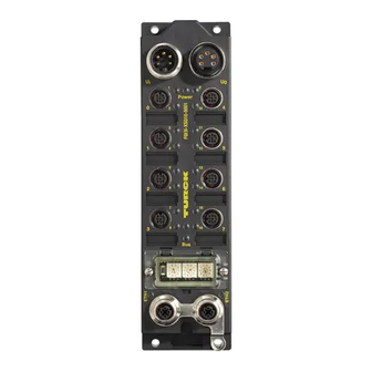
- Page 1 USER MANUAL FGEN-AIM stAtIoNs wIth MultIprotocol FUNTIONALITY Sense it! Connect it! Bus it! Solve it!
- Page 2 No part of this manual may be reproduced in any form (printed, photocopy, microfilm or any other process) or processed, duplicated or distributed by means of electronic systems without written permission of Hans Turck GmbH & Co. KG, Muelheim an der Ruhr. Subject to alterations without notice...
-
Page 3: Table Of Contents
Table of contents About this manual Documentation concept ..........................1-2 Description of symbols used ..........................1-3 General ................................1-4 1.3.1 Prescribed use ......................................1-4 1.3.2 Notes concerning planning/installation of this product ......................1-4 List of revisions ..............................1-5 Multi-protocol functionality General ................................2-2 2.1.1 Protocol dependent functions ................................2-2 FGEN –... - Page 4 3.8.7 Ethernet Statistics ....................................3-19 3.8.8 Links..........................................3-19 3.8.9 Change Admin Password..................................3-20 3.8.10 Parameters ......................................3-21 Status and Control Word of the FGEN-stations ..................3-22 3.9.1 Status Word......................................3-22 3.9.2 Control Word......................................3-22 Digital inputs FGEN-IM16-x001 FGEN-IM16-x001 ............................. 4-2 4.1.1 Technical data ......................................4-2 4.1.2 Wiring diagrams .....................................
- Page 5 7.3.6 Ethernet Link Object (0×F6)................................7-26 VSC-Vendor Specific Classes........................7-28 7.4.1 Class instance of the VSC.................................. 7-28 7.4.2 Gateway Class (VSC 100)................................... 7-29 7.4.3 Process Data Class (VSC102)................................7-31 7.4.4 Digital Versatile Module Class (VSC117) ............................. 7-34 7.4.5 Miscellaneous Parameters Class (VSC 126) ..........................7-35 Diagnostic messages via process data......................
- Page 6 11.3 PROFINET-Error Codes..........................11-4 11.4 Parameters ..............................11-5 11.4.1 General module parameters - parameters for slot 0 (turck-fgen) ..................11-5 11.4.2 Parameters for I/O channels ................................11-5 11.5 Description of user data for acyclic services....................11-7 11.5.1 Description of the acyclic gateway user data..........................11-7 11.5.2 Description of the acyclic I/O-channel user data ........................11-8...
- Page 7 13.1.4 Transmission media.................................... 13-3 13.2 Potential relationships..........................13-4 13.3 Electromagnetic compatibility(EMC ......................13-5 13.3.1 Ensuring electromagnetic compatibility ............................ 13-5 13.3.2 Grounding of inactive metal components..........................13-5 13.3.3 PE connection....................................... 13-5 13.4 Shielding of cables ............................13-6 13.5 Potential compensation..........................13-7 13.5.1 Switching inductive loads ................................
- Page 8 D301271 1013 - FGEN - multi protocol...
-
Page 9: About This Manual
About this manual Documentation concept ..........................1-2 Description of symbols used ........................1-3 General................................ 1-4 1.3.1 Prescribed use ....................................1-4 1.3.2 Notes concerning planning/installation of this product ....................1-4 List of revisions............................1-5 D301271 1013 - FGEN - multi protocol... -
Page 10: Documentation Concept
About this manual Documentation concept This manual contains all information about the TURCK FGEN-product line in protection class IP67 with multi-protocol function. The following chapters contain: the general technical data and station properties, a description of the function and the assembly of the single devices in the product line, ... -
Page 11: Description Of Symbols Used
Description of symbols used Description of symbols used Warning This sign can be found next to all notes that indicate a source of hazards. This can refer to danger to personnel or damage to the system (hardware and software) and to the facility. This sign means for the operator: work with extreme caution. -
Page 12: General
About this manual General Attention Please read this section carefully. Safety aspects cannot be left to chance when dealing with electrical equipment. This manual includes all information necessary for the prescribed use of the FGEN-stations. It has been specially conceived for personnel with the necessary qualifications. 1.3.1 Prescribed use Warning... -
Page 13: List Of Revisions
List of revisions List of revisions In comparison to the previous manual edition, the following changes/ revisions have been made: Table 1-1: Chapter Subject changed List of revisions Web server - remote access/configuration (page 3-16) Changes in th technical data of module, page 5-2 Changes in th technical data of module, page 6-2... - Page 14 About this manual D301271 1013 - FGEN - multi protocol...
-
Page 15: Multi-Protocol Functionality
Multi-protocol functionality General............................2-2 2.1.1 Protocol dependent functions ..............................2-2 – PROFINET ......................................2-2 – EtherNet/IP™ ....................................2-2 D301271 1013 - FGEN - multi protocol... -
Page 16: General
Multi-protocol functionality General The compact I/O-stations of the product line FGEN combine the three Ethernet protocols EtherNet/IP™, Modbus TCP and PROFINET in one device. A multi-protocol device can be operated without intervention of the user (which means, without changes in the parameterization) in all of the three Ethernet protocols mentioned. During the start-up after a power-on, the module runs in "snooping"... -
Page 17: Fgen - General Technical Properties
FGEN – general technical properties General................................ 3-2 General information on FGEN ........................3-3 General technical data ..........................3-4 3.3.1 Technical data ....................................3-4 3.3.2 Dimension drawings ..................................3-5 3.3.3 LED-displays .......................................3-5 Connection possibilities ..........................3-6 3.4.1 Ethernet .......................................3-6 – Ethernet-connection in QC-/FSU-applications........................3-6 3.4.2 Operating/load voltage .................................3-6 –... -
Page 18: General
FGEN – general technical properties General This chapter contains all information about the hardware of the FGEN-stations, the general technical data as well as the connection possibilities, the addressing,etc.. Note Station-specific information can be found in the single station descriptions within the respective chapters of this manual. -
Page 19: General Information On Fgen
General information on FGEN General information on FGEN The FGEN product family offers the following approved features: direct connection of up to 16 digital in- and outputs to an Ethernet-network Protocols: EtherNet/IP™, Modbus TCP and PROFINET RT in one single device ... -
Page 20: General Technical Data
FGEN – general technical properties General technical data 3.3.1 Technical data Table 3-1: Power supply Technical data Operating voltage U (VI) 18 to 30 VDC of the FGEN- stations Load voltage U (VO) 18 to 30 VDC Internal current consumption (from U <... -
Page 21: Dimension Drawings
General technical data 3.3.2 Dimension drawings Figure 3-1: Dimensions for the FGEN- stations ETH1 60,4 42 ETH2 210,5 220,5 3.3.3 LED-displays Table 3-2: Display Meaning Remedy Dimensions for ETHx green Link established,100 Mbps the FGEN- stations green, flashing Ethernet traffic (100 Mbps) yellow Link established,10 Mbps yellow flashing... -
Page 22: Connection Possibilities
FGEN – general technical properties Connection possibilities 3.4.1 Ethernet The connection to Ethernet via the integrated auto-crossing switch is done using two 4-pole, D-coded M12 x 1-Ethernet-female connectors. Figure 3-2: Female connectors M12 x 1 Pin assignment ETH1 ETH2 of the M12 x 1- female connec- tors, 4-pole 1 = TD + (YE) -
Page 23: Analog Inputs And Outputs
Connection possibilities Voltage supply via 7/8’’, 5-pole (FGEN-xxxxx-5xx1) Figure 3-4: 7/8’’ male and 1 = GND 1 = GND 1 = GND female, 2 = GND 2 = GND 2 = GND 3 = FE 5-pole 3 = PE 3 = PE 4 = U 4 = U 4 = U... -
Page 24: Address Assignment
FGEN – general technical properties Address assignment Setting the address mode is done through the 3 rotary coding-switches on the gateway. Figure 3-6: 000: 192.168.1.254 1 - 254: static rotary Decimal rotary 300: BootP coding-switches 400: DHCP for address 500: PGM setting 600: PGM-DHCP 900: F_Reset... -
Page 25: Address Setting Via The Rotary-Mode
Address assignment 3.5.3 Address setting via the rotary-mode switch position: 001 - 254 When using the rotary-mode, the last byte of the station’s IP address can be set via the rotary coding switches. Addresses in the range from 0 to 255 can be allocated, whereas 1 is normally reserved for the default- gateway. -
Page 26: Address Setting Via The Mode Dhcp
FGEN – general technical properties 3.5.5 Address setting via the mode DHCP switch position: 400 Address setting is carried out by a BootP-server in the network after the start-up of the gateway. Note The IP address, as well as the default subnet mask assigned to the station by the DHCP-server, are stored in the station’s EEPROM. -
Page 27: Addressing Via Mode Pgm-Dhcp
Address assignment 3.5.7 Addressing via mode PGM-DHCP switch position: 600 The device sends DHCP-requests until a IP-address is assigned (DHCP-server, PROFINET-controller). The assigned IP-address is stored to the device and the DCHP-client is stopped. Even after a restart of the device, the device sends no further DHCP-requests. PROFINET This mode assures a PROFINET-compliant operation of the modules. -
Page 28: Addressing Via I/O-Assistant 3 (Fdt/Dtm)
The software-tool I/O-ASSISTANT enables direct access to the Ethernet-network via the Ethernet cable. The IP address, as well as the subnet mask of the TURCK Ethernet stations, can be changed according to the application by using the Busaddress Management function of the BL Service Ethernet interface (TCP/IP) in the software I/O-ASSISTANT. - Page 29 Address assignment Figure 3-8: Busaddress management Figure 3-9: Searching network- Nodes in the Busaddress management A Search function in the Busad- dress manage- ment 3-13 D301271 1013 - FGEN - multi protocol...
- Page 30 FGEN – general technical properties Note The access of the IO-ASSISTANT to the station is only possible, if the station already has an IP- address and if it is operated in switch position 500 = PGM or 600 = PGM-DHCP-mode (see also Address assignment (page 3-8)).
-
Page 31: Addressing Via Pgm-Dhcp
Figure 3-11: Web server with Network Configuration SET-button Pushing the SET-button causes a device-restart. Device configuration files The actual device configuration files for the stations can be downloaded from the TURCK-home page www.turck.com. 3-15 D301271 1013 - FGEN - multi protocol... -
Page 32: Web Server - Remote Access/Configuration
FGEN – general technical properties Web server - remote access/configuration Note When working with the webserver of the module, it should be assured, that the browser always reloads the HTML-pages from the module‘s webserver (forced reload). The data should not be loaded from the browser‘s cache memory. This guarantees that the data to be shown are always acutal (module type, module status etc.). -
Page 33: Access Rights
Web server - remote access/configuration 3.8.2 Access rights Without administrator rights, data as general product data and diagnosis data are read only. In order to achieve administrator rights, please log-on to the web server, see Login / password (page 3-17). 3.8.3 Login / password Login to the web server by using the default-password "password". -
Page 34: Network Configuration
FGEN – general technical properties 3.8.4 Network Configuration On the "Network Configuration"-page, network-relevant settings can be changed. Figure 3-14: Web server "Network Configuration" 3-18 D301271 1013 - FGEN - multi protocol... -
Page 35: Station Configuration
The page "Ethernet Statistics" shows information like the port-status, telegram and error counters etc. The page can above all be useful for analyzing network problems. 3.8.8 Links This page contains for example a link to the product page on the TURCK-homepage. 3-19 D301271 1013 - FGEN - multi protocol... -
Page 36: Change Admin Password
FGEN – general technical properties 3.8.9 Change Admin Password Please define an individual password for administrator rights. Default-password: „password“ Note A reset of the device to the default-settings using the switch position 900 "F_Reset" also causes a reset of the password to "password". Figure 3-16: Change Admin Password... -
Page 37: Parameters
Web server - remote access/configuration 3.8.10 Parameters The "Parameters"-page is used to parameterize the station's I/O-channels. Figure 3-17: Web server "Parameters" 3-21 D301271 1013 - FGEN - multi protocol... -
Page 38: Status And Control Word Of The Fgen-Stations
FGEN – general technical properties Status and Control Word of the FGEN-stations The Status as well as the Control Word are mapped into the station's process data. EtherNet/IP™ In EtherNet/IP™, the mapping can be disabled, see Gateway Class (VSC 100), GW Status register (page 7-30) -
Page 39: Digital Inputs Fgen-Im16-X001
Digital inputs FGEN-IM16-x001 FGEN-IM16-x001 ............................4-2 4.1.1 Technical data ....................................4-2 4.1.2 Wiring diagrams ....................................4-2 – Ethernet ......................................4-2 – Power supply ....................................4-2 – Input M12x1 ....................................4-2 4.1.3 Parameters......................................4-3 4.1.4 Diagnostic message of I/O-channels............................4-3 D301271 1013 - FGEN - multi protocol... -
Page 40: Fgen-Im16-X001
Digital inputs FGEN-IM16-x001 FGEN-IM16-x001 The station offers 16 digital inputs for 3-wire pnp sensors. 4.1.1 Technical data Table 4-1: Type designation FGEN-IM16-x001 Technical data Number of channels (16) 3-wire pnp-sensors FGEN-IM16- x0001 Supply (via U 18 ... 30 VDC from operating voltage Supply current <... -
Page 41: Parameters
FGEN-IM16-x001 4.1.3 Parameters Table 4-2: Parameter name Value Description Parameters A default Digital input 0 = normal setting (Inv. DIx) 1 = inverted Inverts the digital input signal. Further information about the parameter data mapping can be found in the fieldbus specific chapters. ... - Page 42 Digital inputs FGEN-IM16-x001 D301271 1013 - FGEN - multi protocol...
-
Page 43: Digital Outputs Fgen-Om16-X001
Digital outputs FGEN-OM16-x001 FGEN-OM16-x001............................5-2 5.1.1 Technical data ....................................5-2 5.1.2 Wiring diagrams ....................................5-2 – Ethernet ......................................5-2 – Power supply ....................................5-2 – Input M12x1 ....................................5-2 5.1.3 Parameters......................................5-3 5.1.4 Diagnostic messages ..................................5-3 D301271 1013 - FGEN - multi protocol... -
Page 44: Fgen-Om16-X001
Digital outputs FGEN-OM16-x001 FGEN-OM16-x001 The station offers 16 digital inputs for DC actuators. 5.1.1 Technical data Table 5-1: Type designation FGEN-OM16-x001 Technical data Number of channels (16) DC actuators FGEN-OM16- x001 Output voltage 18…30 V DC from load voltage Output current per channel 2.0 A, short-circuit proof Load type resistive, inductive, lamp load... -
Page 45: Parameters
FGEN-OM16-x001 5.1.3 Parameters Table 5-2: Parameter name Value Description Parameters A default Output on 0 = activated The output switches on automatically after an overload. setting overcurrent 1 = deactivated The output is switched-off after an overload until a new set- (SROx) command is given (fall and rise). - Page 46 Digital outputs FGEN-OM16-x001 D301271 1013 - FGEN - multi protocol...
-
Page 47: Digital In-/Outputs Fgen-Iom88-X001, Fgen-Xsg16-X001
Digital in-/outputs FGEN-IOM88-x001, FGEN-XSG16-x001 FGEN-IOM88-x001............................6-2 6.1.1 Technical data ....................................6-2 6.1.2 Wiring diagrams ....................................6-3 – Ethernet ......................................6-3 – Power supply ....................................6-3 6.1.3 Parameters......................................6-3 6.1.4 Diagnostic messages ..................................6-4 FGEN-XSG16-000x............................6-5 6.2.1 Technical data ....................................6-5 6.2.2 Wiring diagrams ....................................6-6 – Ethernet ......................................6-6 –... -
Page 48: Fgen-Iom88-X001
Digital in-/outputs FGEN-IOM88-x001, FGEN-XSG16-x001 FGEN-IOM88-x001 The station offers 8 digital inputs for 3-wire pnp sensors and 8 digital outputs for DC actuators. 6.1.1 Technical data Table 6-1: Designation FGEN-IOM88-x001 Technical data Inputs (8) 3-wire pnp-sensors FGEN-IOM88- x001 Supply (via U 18... -
Page 49: Wiring Diagrams
FGEN-IOM88-x001 6.1.2 Wiring diagrams Ethernet → Ethernet (page 3-6) Power supply → Operating/load voltage (page 3-6) Figure 6-1: 3 BU – Wiring diagram 5 PE 4 BK input M12 x 1 1 BN + 2 WH 3 BU – v C0...C3 Figure 6-2: 4 BK + 5 PE... -
Page 50: Diagnostic Messages
Digital in-/outputs FGEN-IOM88-x001, FGEN-XSG16-x001 6.1.4 Diagnostic messages Table 6-3: Diagnostics Description Diagnostic messages SCSx Short circuit at sensor supply of the respective channel SCOx Short circuit at output of the respective channel Further information about the diagnostic data mapping can be found in the fieldbus specific chapters. ... -
Page 51: Fgen-Xsg16-000X
FGEN-XSG16-000x FGEN-XSG16-000x The station is equipped with 16 channels, which can be configured individually, depending on the specific application requirements. Up to sixteen 3 wire pnp sensors or sixteen DC actuators with a maximum output current of 1.4 A per output can be connected. 6.2.1 Technical data Table 6-4:... -
Page 52: Wiring Diagrams
Digital in-/outputs FGEN-IOM88-x001, FGEN-XSG16-x001 6.2.2 Wiring diagrams Ethernet → Ethernet (page 3-6) Power supply → Operating/load voltage (page 3-6) Figure 6-3: Connection of 2 actuators: Wiring 5 PE 4 BK + diagrams 2 WH + 3 BU – Connection of 2 sensors: 3 BU –... -
Page 53: Parameters
FGEN-XSG16-000x 6.2.3 Parameters Table 6-5: Parameter name Value Description Parameters A default Digital input 0 = normal setting (Inv. DI) 1 = inverted Inverts the digital input signal. Output on 0 = activated The output switches on automatically after an overload. overcurrent 1 = deactivated The output is manually switched-off after an overload.until... -
Page 54: Diagnostic Messages
Digital in-/outputs FGEN-IOM88-x001, FGEN-XSG16-x001 6.2.4 Diagnostic messages Table 6-6: Diagnostics Description Diagnostic messages SCSx Short circuit at sensor supply of the respective channel SCOx Short circuit at output of the respective channel Further information about the diagnostic data mapping can be found in the fieldbus specific chapters. ... -
Page 55: Implementation Of Ethernet/Ip
Implementation of EtherNet/IP™ EtherNet/IP Communications Profile ....................... 7-2 7.1.1 I/O Messages......................................7-2 7.1.2 Explicit Messages....................................7-2 7.1.3 Communications profile of FGEN...............................7-2 – Unicast ......................................7-2 – Multicast ......................................7-2 – COS I/O Connection ..................................7-3 – Cyclic I/O Connection .................................7-3 – UCMM.......................................7-3 – Connected Explicit Messaging ..............................7-3 QC - QuickConnect ............................. -
Page 56: Ethernet/Ip Communications Profile
Implementation of EtherNet/IP™ EtherNet/IP Communications Profile EtherNet/IP is based on a connection-oriented communication model. This means that it is only possible to exchange data via specified connections assigned to the devices. Communication between the nodes in the EtherNet/IP network can be carried out either via I/O Messages or Explicit Messages. -
Page 57: Cos I/O Connection
EtherNet/IP Communications Profile COS I/O Connection COS (Change Of State) I/O Connections establish event-controlled connections. This means that the EtherNet/IP devices generate messages as soon as a change of status occurs. Cyclic I/O Connection Messages are triggered time-controlled in Cyclic I/O connections by means of a time generator. UCMM The EtherNet/IP gateway offers the option of establishing explicit messaging via the UCMM port (Unconnected Message Manager Port). -
Page 58: Qc - Quickconnect
For correct cabling with FGEN in QC-applications, see Ethernet-connection in QC-/FSU- applications (page 3-6). 7.2.2 QuickConnect in FGEN TURCK FGEN-stations support QuickConnect. QuickConnect is activated: via the configuration data in the PLC-program per Assembly Class 0×04, Configuration Assembly 106, bit 9 = 1 (see also... -
Page 59: Quickconnect Via Configuration Assembly
QC - QuickConnect QuickConnect via Configuration Assembly The Configuration Assembly is part of the Assembly Class of the device and is defined during the station's configuration in the RS Logix-software by Rockwell Automation. Figure 7-1: Configuration Assembly Note Further information about the configuration of FGEN-stations in the Rockwell software RS Logix can be found in chapter Application example: FGEN for EtherNet/IP™... -
Page 60: Classes And Instances Of The Ethernet/Ip™-Stations
Implementation of EtherNet/IP™ Classes and Instances of the EtherNet/IP™-stations 7.3.1 EtherNet/IP™ Standard Classes The FGEN stations support the following EtherNet/IP™ Standard Classes in accordance with the CIP specification. Table 7-1: Class Code Object name EtherNet/IP™ 01 (0×01) Identity Object (0×01) Standard Classes 04 (0×04) Assembly Object (0×04) -
Page 61: Identity Object (0×01)
Attribute name Get/ Type Description Instance attributes 1 (0×01) VENDOR UINT Contains the vendor ID. TURCK = 48 2 (0×02) PRODUCT TYPE UINT Indicates the general type of product. Communications Adapter = 0×0C 3 (0×03) PRODUCT CODE UINT Identifies a particular product within a device type. - Page 62 Implementation of EtherNet/IP™ Device Status Table 7-4: Name Definition Device Status 0 to 1 reserved Default = 0 Configured TRUE = 1 → The application of the device has been configured (≠ default-settings). reserved Default = 0 4 to 7 Extended Device 0011 = no I/O connection established Status...
-
Page 63: Assembly Object (0×04)
Classes and Instances of the EtherNet/IP™-stations 7.3.3 Assembly Object (0×04) Assembly Objects bind attributes of multiple objects to allow data to or from each object to be sent or received over a single connection. The following description of the Ethernet Link Object is taken from the CIP specification, Vol. 2, Rev. 2.1 by ODVA &... - Page 64 Implementation of EtherNet/IP™ Process data instances Instance 101 Contains the station’s input data (static length 256 bytes). 2 Bytes status information (see page 3-22) + process data Instance 102 Contains the station’s output data (static length 256 bytes). 2 Bytes Control data (mapped, but not defined) + process data Instance 103 und Instance 104 In- and output assembly instances with variable assembly sizes.
-
Page 65: Process Data Mapping Fgen-Im16-X001
Classes and Instances of the EtherNet/IP™-stations Process data mapping FGEN-IM16-x001 No diagnostic message, Status- and control-word can be deactivated, see page 3-22. IN = 4 Byte OUT = 2 Byte Byte Bit 7 Bit 6 Bit 5 Bit 4 Bit 3 Bit 2 Bit 1... - Page 66 Implementation of EtherNet/IP™ Manufacturer specific (scheduled diagnostics) activated, see page 7-36 IN = 8 Byte OUT = 2 Byte Byte Bit 7 Bit 6 Bit 5 Bit 4 Bit 3 Bit 2 Bit 1 Bit 0 Status Diag Warn Inputs C3P2 C3P4...
-
Page 67: Process Data Mapping Fgen-Om16-X001
Classes and Instances of the EtherNet/IP™-stations Process data mapping FGEN-OM16-x001 No diagnostic message, Status- and control-word can be deactivated, see page 3-22. IN = 2 Byte OUT = 4 Byte Byte Bit 7 Bit 6 Bit 5 Bit 4 Bit 3 Bit 2 Bit 1... - Page 68 Implementation of EtherNet/IP™ Manufacturer specific (scheduled diagnostics) activated, see page 7-36 IN = 8 Byte OUT = 4 Byte Byte Bit 7 Bit 6 Bit 5 Bit 4 Bit 3 Bit 2 Bit 1 Bit 0 Status Diag Warn Diagnos I/O Diag tics...
-
Page 69: Process Data Mapping Fgen-Iom88-X001
Classes and Instances of the EtherNet/IP™-stations Process data mapping FGEN-IOM88-x001 No diagnostic message, Status- and control-word can be deactivated, see page 3-22. IN = 4 Byte OUT = 4 Byte Byte Bit 7 Bit 6 Bit 5 Bit 4 Bit 3 Bit 2 Bit 1... - Page 70 Implementation of EtherNet/IP™ Manufacturer specific (scheduled diagnostics) activated, see page 7-36 IN = 8 Byte OUT = 4 Byte Byte Bit 7 Bit 6 Bit 5 Bit 4 Bit 3 Bit 2 Bit 1 Bit 0 Status Diag Warn Inputs DI1 C0P2 C3P2...
-
Page 71: Process Data Mapping Fgen-Xsg16-X001
Classes and Instances of the EtherNet/IP™-stations Process data mapping FGEN-XSG16-x001 No diagnostic message, Status- and control-word can be deactivated, see page 3-22. IN = 4 Byte OUT = 4 Byte Byte Bit 7 Bit 6 Bit 5 Bit 4 Bit 3 Bit 2 Bit 1... - Page 72 Implementation of EtherNet/IP™ Summarized diagnostics activated, see page 7-36 IN = 6 Byte OUT = 4 Byte Byte Bit 7 Bit 6 Bit 5 Bit 4 Bit 3 Bit 2 Bit 1 Bit 0 Status Diag Warn Inputs DI1 C0P2 C3P2 C3P4 C2P2...
- Page 73 Classes and Instances of the EtherNet/IP™-stations Manufacturer specific (scheduled diagnostics) activated, see page 7-36 IN = 10 Byte OUT = 4 Byte Byte Bit 7 Bit 6 Bit 5 Bit 4 Bit 3 Bit 2 Bit 1 Bit 0 Status Diag Warn...
-
Page 74: Meaning Of Process Data Bits
Implementation of EtherNet/IP™ Meaning of Process data bits Table 7-9: Name Meaning Meaning of Process data bits I/O-data DI = digital input DO = digital output C = connector P = Pin Diagnostics DiagWarn see VSC 100, attr. 109 (6Dh), Status register 2 (page 7-30) I/O Diag Summarized diagnostic message of I/Os... -
Page 75: Connection Manager Object (0×06)
Classes and Instances of the EtherNet/IP™-stations 7.3.4 Connection Manager Object (0×06) This object is used for connection and connectionless communications, including establishing connections across multiple subnets. The following description of the Ethernet Link Object is taken from the CIP specification, Vol. 2, Rev. 2.1 by ODVA &... -
Page 76: Tcp/Ip Interface Object (0×F5)
Implementation of EtherNet/IP™ 7.3.5 TCP/IP Interface Object (0×F5) The following description of the Ethernet Link Object is taken from the CIP specification, Vol. 2, Rev. 1.1 by ODVA & ControlNet International Ltd. and adapted to FGEN. Class Attributes Table 7-11: Attr. - Page 77 Classes and Instances of the EtherNet/IP™-stations Common services Table 7-13: Service code Class Instance Service name Common services 01 (0x01) Get_Attribute_All 02 (0x02) Set_Attribute_All 14 (0x0E) Get_Attribute_Single 16 (0×10) Set_Attribute_Single Interface Status The Status attribute indicates the status of the TCP/IP network interface. Refer to the state diagram, Figure 7-2: TCP/IP object state diagram (acc.
- Page 78 Implementation of EtherNet/IP™ Configuration Control The Configuration Control attribute is used to control network configuration options. Table 7-16: Bit(s) Name Definition Configuration Startup Determines how the device shall obtain its initial configuration Control Configuration 0 = The device shall use the interface configuration values previously stored (for example, in non-volatile memory or via hardware switches, etc).
- Page 79 Classes and Instances of the EtherNet/IP™-stations Figure 7-2: TCP/IP object Non-existent state diagram (acc. to CIP Powerup Reset Status = Spec., Vol.2, Rev. 0×00000000 1.1) Obtaining initial configuration BOOTP/DHCP disabled and BOOTP/DHCP stored config. BOOTP OR disabled and valid DHCP enabled stored config.
-
Page 80: Ethernet Link Object (0×F6)
INTERFACE FLAGS G DWORD Table 7-19: Interface flags 3 (0×03) PHYSICAL ARRAY OF Contains the interface’s MAC address ADDRESS USINT (TURCK: 00:07:46:××:××:××) 6 (0×06) INTERFACE 2 WORD Allows port-wise changes of the Ethernet- CONTROL settings 7 (0×07) INTERFACE TYPE 10 (0×0A) - Page 81 Classes and Instances of the EtherNet/IP™-stations Table 7-19: Bits Name Definition Default value Interface flags 2 to 4 Negotiation Status Indicates the status of the automatic Depends on duplex-negotiation (auto-negotiation) application 0 = Auto-negotiation in progress 1 = Auto-negotiation and speed detection failed.
-
Page 82: Vsc-Vendor Specific Classes
Implementation of EtherNet/IP™ VSC-Vendor Specific Classes In addition to supporting the above named CIP Standard Classes, the FGEN-stations support the vendor specific classes described in the following. Table 7-21: Class Code Name Description VSC-Vendor dec. Specific Classes (hex.) 100 (64h) Gateway Class, page 7-29 Contains data and settings concerning the... -
Page 83: Gateway Class (Vsc 100)
VSC-Vendor Specific Classes 7.4.2 Gateway Class (VSC 100) This class contains all information which refers to the whole station not to the different I/O channels. Class instance Note Please refer to paragraph Class instance of the VSC (page 7-28) for the description of the class instance for the VSC. -
Page 84: Object Instance 2
Implementation of EtherNet/IP™ Object Instance 2 Table 7-24: Attr. No. Attribute name Get/ Type Description Object Instance 2, dec. Gateway Instance (hex.) Status register 2 STRUCT The Status Word contains general station (6Dh) status information: Station – Bit 15: reserved –... -
Page 85: Process Data Class (Vsc102)
VSC-Vendor Specific Classes Table 7-24: Attr. No. Attribute name Get/ Type Description Object Instance 2, dec. Gateway Instance (hex.) Disable Protocols Get/ UINT Deactivation of the used Ethernet-protocols. (0×8C) Bit-assignment of the protocols: 0 = EtherNet/IP™ (can not be deactivated via the EtherNet/IP-interface) 1 = Modbus/TCP 2 = PROFINET... -
Page 86: Object Instance 3, Diagnostic Instance
Implementation of EtherNet/IP™ Object instance 2, standard output process data (compressed) Table 7-26: Attr. No. Attribute name Get/ Type Description Object instance 2, dec. (hex.) standard output process data 100 (64h) Max object USINT Contains the number of the last object (compressed) attribute attribute to be implemented. -
Page 87: Object Instance 4, Cos/Cyclic Instance
VSC-Vendor Specific Classes Object Instance 4, COS/CYCLIC instance Table 7-28: Attr. No. Attribute name Get/ Type Description Object Instance 4, dec. COS/CYCLIC (hex.) instance 104 (68h) COS data ENUM The actual data are loaded to the non- mapping USINT volatile memory of the station. Changes become valid after a start-up! 0 = standard: Data of COS message →... -
Page 88: Digital Versatile Module Class (Vsc117)
Implementation of EtherNet/IP™ 7.4.4 Digital Versatile Module Class (VSC117) This class contains all information and parameters for the station’s digital I/O channels. Object Instance Table 7-29: Attr. No. Attribute name Get/ Type Description Object Instance dec. (hex.) Max object USINT Contains the number of the last object (64h) attribute... -
Page 89: Miscellaneous Parameters Class (Vsc 126)
VSC-Vendor Specific Classes Table 7-29: Attr. No. Attribute name Get/ Type Description Object Instance dec. (hex.) Diagnostic data Short circuit DWORD Short-circuit at output channel (77h) output error_1 Short circuit DWORD Sensor short-circuit at channel (79h) sensor error_1 Parameter data Invert input DWORD The input signal is inverted (channel 1 to... -
Page 90: Diagnostic Messages Via Process Data
Implementation of EtherNet/IP™ Diagnostic messages via process data Besides the evaluation of diagnostic data via Explicit Messages, FGEN with EtherNet/IP™ offers the possibility of mapping diagnostic data into the process data (see also the stations‘ process data mappings (page 7-11 ff.). - Page 91 Application example: FGEN for EtherNet/IP™ with Allen Bradley PLC and RS Logix 5000 General................................ 8-2 8.1.1 Used hard-/ software ..................................8-2 – Hardware......................................8-2 – Software......................................8-2 Network configuration ..........................8-3 8.2.1 Configuration of the network in "RS Logix 5000".........................8-3 – Configuration of the controller...............................8-3 –...
-
Page 92: General
Application example: FGEN for EtherNet/IP™ with Allen Bradley PLC and RS Logix 5000 General The following example shows detailed information about the connection of FGEN-stations for EtherNet/IP™ to an Allen Bradley PLC. 8.1.1 Used hard-/ software Hardware Hardware used in this example: ... -
Page 93: Network Configuration
Network configuration Network configuration The FGEN-stations are delivered with the IP address 192.168.1.1. Note In order to build up the communication between the FGEN-station and a PLC/ PC or a network interface card, both devices have to be hosts in the same network. To achieve this, you have either ... - Page 94 Application example: FGEN for EtherNet/IP™ with Allen Bradley PLC and RS Logix 5000 Your project will be opened offline. In order to configure the network, please right-click "I/O Configuration" and select "new Module" to add the first host, the EtherNet/IP™ bridge, to the network. Open "Communications"...
-
Page 95: Dimensions For The Fgen-Stations
Network configuration Dimensions for the FGEN-stations 1 Add the stations to the I/O configuration by using a right-click on the EtherNet/IP™ bridge module 1756-ENBT/A and select "New Module". Figure 8-6: Adding an FGEN to the I/O configuration 2 Open "Communications" and select the entry "Generic Ethernet Module" to configure the station. Figure 8-7: Add generic Ethernet... - Page 96 Application example: FGEN for EtherNet/IP™ with Allen Bradley PLC and RS Logix 5000 4 In the Assembly Instances 103 and 104, please enter the connection parameters of the station. Figure 8-8: Configuration of FGEN-IOM- 5001 Note If the variable Assembly Instances 103 and 104 (see page 7-9) are used, the Connection Parameters have to be set according to the actual station configuration which means, the in-...
- Page 97 Network configuration Figure 8-11: Set connection options for FGEN 7 The both stations are now added to the project tree. Figure 8-12: Project tree with FGEN-stations D301271 1013 - FGEN - multi protocol...
-
Page 98: Downloading The I/O Configuration
Application example: FGEN for EtherNet/IP™ with Allen Bradley PLC and RS Logix 5000 8.2.2 Downloading the I/O configuration 1 If the configuration of the network is completed, it can be downloaded to the controller by using for example the "Communication → Download" command. 2 In the "Download"... - Page 99 Network configuration Once the I/O configuration is downloaded and the controller is in "Run" or "Remote Run" mode, the I/O-data mapping of the FGEN-stations is shown in the "Controller Tags": Figure 8-17: Controller Tags The controller tags are divided into: ...
-
Page 100: I/O Data Mapping
Application example: FGEN for EtherNet/IP™ with Allen Bradley PLC and RS Logix 5000 I/O data mapping Each station is now accessible via the controller tags for viewing input data and/or forcing outputs. The data mapping depends on process data mappings of the configured FGEN-modules (see chapter 7.3.3, Assembly Object... -
Page 101: Process Data Access
Process data access Process data access 8.4.1 Setting outputs Example: FGEN-IOM88-5001 To set the outputs "0" and "1" at the station , bit 0 bit 1 in output data word 1 (IOM88:O.Data [1]) have to be set (see above Figure 8-16:, I/O data mapping). - Page 102 Application example: FGEN for EtherNet/IP™ with Allen Bradley PLC and RS Logix 5000 1 The counter counts upwards. 2 The counter value is moved to the outputs of the FGEN-XSG16-4001, Word XSG16:0.Data [1]. 3 The counter is set to "0" by setting the variable "xReset" (BOOL) to "1". "xReset"...
-
Page 103: Activating Quickconnect
Activating QuickConnect Activating QuickConnect The QuickConnect-function of the FGEN-stations is activated via: Configuration Assembly, byte 9, bit 1. Figure 8-22: Activating the QuickConnect- function Note Further information about QuickConnect can also be found in chapter QuickConnect in FGEN (page 7-4). - Page 104 Application example: FGEN for EtherNet/IP™ with Allen Bradley PLC and RS Logix 5000 8-14 D301271 1013 - FGEN - multi protocol...
-
Page 105: Implementation Of Modbus Tcp
Implementation of Modbus TCP Common Modbus description........................9-2 9.1.1 Protocol description..................................9-3 9.1.2 Data model ......................................9-4 Implemented Modbus functions....................... 9-6 Modbus registers............................9-7 9.3.1 Data width of the I/O-modules in the modbus-register area..................9-10 9.3.2 Register mapping of the FGEN-stations..........................9-11 –... -
Page 106: Common Modbus Description
Implementation of Modbus TCP Common Modbus description Note The following description of the Modbus protocol is taken from the Modbus Application Protocol Specification V1.1 of Modbus-IDA. Modbus is an application layer messaging protocol, positioned at level 7 of the OSI model, that provides client/server communication between devices connected on different types of buses or networks. -
Page 107: Protocol Description
Common Modbus description 9.1.1 Protocol description The Modbus protocol defines a simple protocol data unit (PDU) independent of the underlying communication layers. The mapping of Modbus protocol on specific buses or network can introduce some additional fields on the application data unit (ADU). Figure 9-2: Modbus tele- gram acc. -
Page 108: Data Model
Implementation of Modbus TCP If an error related to the Modbus function requested occurs, the field contains an exception code that the server application can use to determine the next action to be taken. Figure 9-4: Modbus data transmission (acc. to Modbus-IDA) 9.1.2 Data model... - Page 109 Common Modbus description FGEN devices have only one data block, whose data can be accessed via different Modbus functions. The access can be carried out either via registers (16-bit-access) or, for some of them, via single-bit- access. Figure 9-5: Picture of the data memory of the FGEN modules...
-
Page 110: Implemented Modbus Functions
Implementation of Modbus TCP Implemented Modbus functions The FGEN stations for Modbus TCP support the following functions for accessing process data, parameters, diagnostics and other services. Table 9-2: Function codes Implemented Function functions Description Read Coils Serves for reading multiple output bits. Read Discrete Inputs Serves for reading multiple input bits. -
Page 111: Modbus Registers
Modbus registers Modbus registers Note Table 9-5:, page 9-10 shows the register mapping for the different Modbus addressing methods. Table 9-3: Address (hex.) Access Description Ident number of the station A ro = read only 0x0000 to 0x01FF packed process data of inputs rw = read/write (process data length of the modules →... - Page 112 Implementation of Modbus TCP Table 9-3: Address (hex.) Access Description Ident number of the station 0x1141 active protocol 0 = EtherNet/IP™ 1 = Modbus/TCP 2 = PROFINET 15 = web server 0x2400 System voltage U [mV]: 0 if < 18 V 0x2401 Load voltage U [mV]: 0 if <...
- Page 113 Modbus registers The following table shows the register mapping for the different Modbus addressing methods Table 9-4: Description Decimal 5-digit Modicon Mapping of Modbus regis- ters (holding registers) packed input data 0×0000 40001 400001 0×01FF 40512 400512 packed output data 0×0800 2048 42049...
-
Page 114: Data Width Of The I/O-Modules In The Modbus-Register Area
Implementation of Modbus TCP Table 9-4: Description Decimal 5-digit Modicon Mapping of Modbus regis- ters (holding registers) diagnostics (max. 2 registers per station) 0×A000, 40960, 440961, 00A001 40961 440962 diagnostics (max. 4 registers per station) 0×B000, 45056, 445057, 0×B001 45057 445058 9.3.1 Data width of the I/O-modules in the modbus-register area... -
Page 115: Register Mapping Of The Fgen-Stations
Modbus registers 9.3.2 Register mapping of the FGEN-stations FGEN-IM16-x001 register Bit 7 Bit 6 Bit 5 Bit 4 Bit 3 Bit 2 Bit 1 Bit 0 packed input data 0×0000 Inputs C3P2 C3P4 C0P2 C2P4 C1P2 C1P4 C0P2 C0P4 DI15 DI14 DI13 DI12... - Page 116 Implementation of Modbus TCP FGEN-OM16-x001 register Bit 7 Bit 6 Bit 5 Bit 4 Bit 3 Bit 2 Bit 1 Bit 0 packed input data 0×0001 Status Diag Word Warn 0×0002 group I/O Diag diagnostic packed output data 0×0800 C3P2 C3P4 C2P2 C2P4...
- Page 117 Modbus registers FGEN-IOM88-x001 register Bit 7 Bit 6 Bit 5 Bit 4 Bit 3 Bit 2 Bit 1 Bit 0 packed input data 0×0000 Inputs C3P2 C3P4 C0P2 C2P4 C1P2 C1P4 C0P2 C0P4 0×0001 Status Diag Word Warn 0×0002 group I/O Diag diagnostic Inputs...
-
Page 118: Fgen-Xsg16-X001
Implementation of Modbus TCP FGEN-XSG16-x001 register Bit 7 Bit 6 Bit 5 Bit 4 Bit 3 Bit 2 Bit 1 Bit 0 packed input data 0×0000 Inputs C3P2 C3P4 C0P2 C2P4 C1P2 C1P4 C0P2 C0P4 DI15 DI14 DI13 DI12 DI11 DI10 C7P2 C7P4... -
Page 119: Meaning Of The Register Bits
Modbus registers Meaning of the register bits Table 9-6: Name Meaning Meaning of the register bits I/O-data DI = digital input DO = digital output C = connector P = Pin Diagnostics DiagWarn Register 100Ch: "Station status" (page 9-16) I/O Diag Summarized diagnostic message of I/Os SCSx... -
Page 120: Register 100Ch: "Station Status
Implementation of Modbus TCP 9.3.3 Register 100Ch: "Station status" This register contains a general gateway/ station status. Table 9-7: Name Description Register 100Ch: Station status Station The Force Mode is activated, which means, the actual output values may no match the ones defined and sent by the field bus. -
Page 121: Register 1130H: „Modbus-Connection-Mode
Modbus registers 9.3.4 Register 1130h: „Modbus-Connection-Mode“ This register defines the behavior of the Modbus connections: Table 9-8: Name Register 1130h: – Description Modbus- Connection- 15 to 2 reserved Mode MB_ImmediateWritePermission – 0: With the first write access, a write authorization for the respective Modbus-connection is requested. -
Page 122: Register 0×113E Und 0×113F: „Save Modbus-Connection-Parameters
Implementation of Modbus TCP 9.3.7 Register 0×113E und 0×113F: „Save Modbus-Connection-Parameters“ Registers 0×113E and 0×113F are used for the non-volatile saving of parameters in registers 0×1120 and 0×1130 to 0×113B. or this purpose, write "0×7361" in register 0×113E. To activate the saving of the registers, write "0×7665"... -
Page 123: Bit Areas: Mapping Of Input-Discrete- And Coil-Areas
Bit areas: mapping of input-discrete- and coil-areas Bit areas: mapping of input-discrete- and coil-areas The digital in- and outputs can be read and written (for outputs) as registers in the data area of the packed in- and output process data. Note In the packed process data, the digital I/O data are stored following the variable in- and output data area of the intelligent I/Os, which means they are stored with a variable offset,... -
Page 124: Error Behavior Of Outputs (Watchdog)
Implementation of Modbus TCP Error behavior of outputs (watchdog) In case of a failure of the Modbus communication, the outputs’ behavior is as follows, depending on the defined time for the Watchdog (register 0x1120, page 9-7): watchdog = 0 ms (default) →... -
Page 125: Parameters And Diagnostic Messages Of The I/O Channels
Parameters and diagnostic messages of the I/O channels Parameters and diagnostic messages of the I/O channels Note Please find explanations regarding parameters and diagnostic messages in the section Register mapping of the FGEN-stations (page 9-11). 9-21 D301271 1013 - FGEN - multi protocol... - Page 126 Implementation of Modbus TCP 9-22 D301271 1013 - FGEN - multi protocol...
-
Page 127: Application Example Fgen For Modbus Tcp With Codesys Win V3
10 Application example FGEN for Modbus TCP with CODESYS Win V3 10.1 Used hard-/ software..........................10-2 10.1.1 Hardware......................................10-2 10.1.2 Software......................................10-2 10.2 Network configuration ..........................10-3 10.3 Programming with CoDeSys ........................10-4 10.3.1 Predefined feature sets ................................10-4 10.3.2 Creating a new project................................10-5 10.3.3 Defining the communication settings........................... -
Page 128: Used Hard-/ Software
Application example FGEN for Modbus TCP with CODESYS Win V3 10.1 Used hard-/ software 10.1.1 Hardware FGEN-IOM88-5001 (IP-address 192.168.1.90) FGEN-XSG16-5001 (IP-address 192.168.1.107) 10.1.2 Software CODESYS 3.4, SP3, Patch 1 PLC: CODESYS Control Win V3 (3.4.3.10) 10-2 D301271 1013 - FGEN - multi protocol... -
Page 129: Network Configuration
Network configuration 10.2 Network configuration FGEN-stations are delivered in the address-mode "PGM-DHCP", switch-position "600" and can be reached using IP-address 192.168.1.254 . Note In order to build up the communication between the FGEN-station and a PLC/ PC or a network interface card, both devices have to be hosts in the same network. -
Page 130: Programming With Codesys
Application example FGEN for Modbus TCP with CODESYS Win V3 10.3 Programming with CODESYS Open CODESYS via "Start → All programs → 3S CoDeSys → CoDeSys → CoDeSys V 3.4“. 10.3.1 Predefined feature sets In this example, CODESYS is run with the "Professional feature set" not with the "Standard feature set". This setting has influence on different CODESYS functions and can be changed via "Tools →... -
Page 131: Creating A New Project
Programming with CODESYS 10.3.2 Creating a new project 1 Create a new CODESYS-project using the "File → New project" command. Figure 10-2: New project 2 Select "Standard project" and define a project name. Figure 10-3: Standard project 10-5 D301271 1013 - FGEN - multi protocol... - Page 132 Application example FGEN for Modbus TCP with CODESYS Win V3 3 Please define also your preferred programming language. In this example, Structured Text is used. Figure 10-4: Selection of CODESYS Con- trol Win V3 4 The new project is created. 5 In CODESYS, the project tree is build up as follows: Figure 10-5: Project tree...
-
Page 133: Defining The Communication Settings
Programming with CODESYS 10.3.3 Defining the communication settings Double-clicking the "Device (CODESYS Control Win V3)" opens the corresponding editors. The communication path (Gateway) to the HMI is defined in the "Communication Settings" tab. Gateway definition 1 Use the "Add gateway"-button to open the dialog box "Gateway" and, where necessary, assign a new gateway name. -
Page 134: Setting The Communication Path
Application example FGEN for Modbus TCP with CODESYS Win V3 Setting the communication path 1 Mark the gateway and scan the network via the respective button. 2 The network card of your PC will be found and set as active path. Figure 10-7: Set communica- tion... -
Page 135: Adding The Ethernet Adapter
Programming with CODESYS 10.3.4 Adding the Ethernet Adapter Open again the context menu by right-clicking the Device entry. In the dialog "Add Device" select the 3S Ethernet Adapter under "fieldbusses → Ethernet Adapter" and add it to the project tree. Figure 10-8: Adding the Ethernet... -
Page 136: Adding The Modbus Master
Application example FGEN for Modbus TCP with CODESYS Win V3 10.3.5 Adding the Modbus master A right-click on the Ethernet-master opens the context menu. Select "Add Device" and add the Modbus TCP-master to the network. Figure 10-9: Adding the Modbus master 10-10 D301271 1013 - FGEN - multi protocol... -
Page 137: Adding A Modbus Tcp Slave
Programming with CODESYS 10.3.6 Adding a Modbus TCP slave 1 Now, add the Modbus TCP slaves to the project and rename them if necessary. Figure 10-10: Selecting a slave 10-11 D301271 1013 - FGEN - multi protocol... - Page 138 Application example FGEN for Modbus TCP with CODESYS Win V3 2 Again, a double-click onto the slave in the project tree opens the respective editors. 3 In the "Modbus TCP Slave“"-tab, set the nodes IP-address (in this example: 192.168.1.90 for FGEN- IOM88-5001 und 192.168.1.107 for FGEN-XSG16-5001).
-
Page 139: Programming (Example Program)
Programming with CODESYS 10.3.7 Programming (example program) The programming is done under PLC-PRG in the project tree. This example is programmed in Structured Text (ST) as defined under Creating a new project (page 10-5). Small example program 1 The counter counts 2 Counter-reset via setting the variable "xReset"... -
Page 140: Codesys: Global Variables
Application example FGEN for Modbus TCP with CODESYS Win V3 10.3.8 CODESYS: Global variables Global variables are defined either in the Global Variable List (see page 10-15) or directly in the I/O Mappings of the single stations. Figure 10-13: Example for the definition of a global vari- able... -
Page 141: Modbus Channels
Programming with CODESYS Global variable list The creation of a "Global Variable List" is possible, too: right-click to "APPL → Add object → Global Variable List". Define the global variables The global variables are also automatically exported when building the project, if they have been chosen for export in the symbol configuration. -
Page 142: Modbus Data Mapping
9, section Register mapping of the FGEN-stations (page 9-11). The TURCK-Software "I/O-ASSISTANT" offers the feature of creating a Modbus report for each Modbus- station, which shows the mapping for the respective station (see below). Modbus mapping (I/O-ASSISTANT) Figure 10-15: Modbus report... -
Page 143: Setting The Modbus Channels (Examples)
Programming with CODESYS Setting the Modbus channels ( examples) 1 Reading of %QW0 and mapping of the counter value (VAR "Counter", see PLC_PRG, page 10-13) to the output byte of the station FGEN-XSG16-5001 (%QW0). Write: %QW0 – Access Type: Write Single Register (function code 06) –... - Page 144 Application example FGEN for Modbus TCP with CODESYS Win V3 Mapping: counter value to %QW0 – The mapping of the counter value (VAR "Counter") to the station 's output register is done the the "ModbusTCPSlave I/O Mapping". Double click the field "variable" in the respective line. Use the "..."-button to open the dialog box "Input Assistant"...
- Page 145 Programming with CODESYS 2 Read: Bit 0 at FGEN-IOM88-5001 → resetting the counter (with "xReset" = 1) Read: %IW0 – Access Type: Read Holding Registers (function code 03) – Read Register, Offset: 0×0000 (see Register mapping of the FGEN-stations, FGEN-XSG16-x001 (page 9-14)) Figure 10-18: Modbus...
- Page 146 Application example FGEN for Modbus TCP with CODESYS Win V3 Mapping: "xReset" (global variable) to %IX0.0 in %IW2 – "xReset" is mapped to the first bit in %IW0 of FGEN-IOM88-5001. This is done in the "ModbusTCPSlave I/O Mapping". – Double click the field "variable" in the respective line. Use the "..."-button to open the dialog box "Input Assistant"...
- Page 147 Programming with CODESYS 3 Read: Status byte of the station FGEN-XSG16-5001 – Access Type: Read Holding Registers (function code 03) – Read Register, Offset: 0×0001 (see Register mapping of the FGEN-stations, FGEN-XSG16-x001 (page 9-14)) – The status word of the FGEN-XSG16-5001 is read from register 0x0001. Figure 10-20: Setting the Modbus...
- Page 148 Application example FGEN for Modbus TCP with CODESYS Win V3 4 Write: Parameters of the station FGEN-XSG16-5001 target → inverting the input signal at channel 5 Writing parameters is normally done once during the program start and is thus not set as a "normal" Modbus channel under "ModbusSlave Channel", but as an Initialization channel under "Modbus Slave Init"...
-
Page 149: Building, Login And Start
Programming with CODESYS 10.3.10 Building, login and start 1 The WIN V3-PLC has to be running. This is done in the Windows-task bar: Figure 10-22: Starting the WIN V3-PLC 2 Building the program: Figure 10-23: Building the program 3 Login: Figure 10-24: Login 10-23... - Page 150 Application example FGEN for Modbus TCP with CODESYS Win V3 4 Start the program: Figure 10-25: Starting the program 10-24 D301271 1013 - FGEN - multi protocol...
-
Page 151: Reading Out The Process Data
Programming with CODESYS 10.3.11 Reading out the process data The station's process data are shown in the register tab "ModbusTCPSlave I/O Mapping". Note In order assure a regular updating of the process data, activate the function "Always update variables". Figure 10-26: Modbus TCP Slave I/O Mapping... -
Page 152: Evaluation Of The Status Word Of Fgen-Xsg16-5001 (%Iw1)
Application example FGEN for Modbus TCP with CODESYS Win V3 10.3.12 Evaluation of the status word of FGEN-XSG16-5001 (%IW1) According to the definition of the Modbus communication channel (see Setting the Modbus channels (examples), example 4, page 10-21), %IW1 contains station's the status-word. the message is to be interpreted as follows: %IW 2, "actual value"... -
Page 153: Implementation Of Profinet
GSDML-file ..............................11-3 11.3 PROFINET-Error Codes ..........................11-4 11.4 Parameters..............................11-5 11.4.1 General module parameters - parameters for slot 0 (turck-fgen)................11-5 11.4.2 Parameters for I/O channels ..............................11-5 11.5 Description of user data for acyclic services ..................11-7 11.5.1 Description of the acyclic gateway user data ........................11-7 11.5.2... -
Page 154: Fsu - Fast Start-Up (Prioritized Startup)
Ethernet-connection in QC-/FSU- applications (page 3-6). 11.1.2 FSU in FGEN TURCK FGEN-stations support the prioritized start-up FSU. In order to enable FSU, the field bus nodes have to be configured respectively in the configurator HW Config in the Step 7-software (Siemens). Note... -
Page 155: Gsdml-File
GSDML-file 11.2 GSDML-file The actual device configuration file for FGEN can be downloaded from the TURCK-home page www.turck.com. Table 11-1: Station GSD file Designation of FGEN GSDML-V2.0-Turck-FGEN-JJJJMMTT-xxxxxx.xml the GSDML-files 11-3 D301271 1013 - FGEN - multi protocol... -
Page 156: Profinet-Error Codes
Implementation of PROFINET 11.3 PROFINET-Error Codes The channel specific diagnostic messages are defined as follows: Table 11-2: Value (dec.) Diagnosis Channel- Error codes (1 to 9 according to the standards) specific diag- nostics Short-circuit at output Undervoltage: Undervoltage channel 0: Undervoltage at U Undervoltage channel 1: Undervoltage at U Error codes (16 to 31 manufacturer specific) External error:... -
Page 157: Parameters
Parameters Two types of parameters have to be distinguished for the FGEN-stations, the PROFINET parameters of a station and the specific parameters of the I/O-channels. 11.4.1 General module parameters - parameters for slot 0 (turck-fgen) Table 11-3: Parameter name Value... - Page 158 Implementation of PROFINET Table 11-4: Parameter name Value Meaning Parameters for I/O channels Output on 0 = automatic The output switches on automatically after an overcurrent recovery overload. 1 = recovery at signal change The output is manually switched-off and on again.
-
Page 159: Description Of User Data For Acyclic Services
Station designation STRING Designation of the station (slot 0). Station revision STRING Firmware revision of the station Vendor-ID WORD Ident number for TURCK Station name STRING The device name assigned to the station. Station type STRING Device type of the station... -
Page 160: Description Of The Acyclic I/O-Channel User Data
Implementation of PROFINET Table 11-5: Index Name Data Type r/w Comment Module Applica- (dec.) tion Instance 45041 I&M1-functions STRING I&M tag function and location (0×AFF1) [54] 45042 I&M2-functions STRING I&M tag function and location (0×AFF2) [16] 45043 I&M3-functions STRING (0×AFF3) [54] 45044 I&M4-functions... - Page 161 12 Application example: FGEN for PROFINET with a Siemens S7 12.1 Application example..........................12-2 12.1.1 General......................................12-2 12.1.2 Example network ..................................12-2 12.1.3 New project in the Simatic Manager............................12-3 12.1.4 Setting the PG/PC-interface ..............................12-3 12.1.5 Installation of the GSDML-files..............................12-4 12.1.6 Adding PROFINET network nodes ............................
-
Page 162: Application Example: Fgen For Profinet With A Siemens S7
Application example: FGEN for PROFINET with a Siemens S7 12.1 Application example 12.1.1 General In order to configure the connection of FGEN-stations for PROFINET to a Siemens PLC S7, the software package "SIMATIC Manager" version 5.5 from Siemens is used. 12.1.2 Example network ... -
Page 163: New Project In The Simatic Manager
Application example 12.1.3 New project in the Simatic Manager 1 Create a new project in the Simatic Manager using the "File →New"-command 2 Add a Simatic station to the project using the "Insert → station..."-command. In this example a "Simatic 300 station" is used. Figure 12-1: Selecting a Simatic station... -
Page 164: Installation Of The Gsdml-Files
1 In the hardware configuration "HW config", open the "Options→ Install GSD file" command in order to install new GSD-files. Figure 12-3: Install GSD file 2 Define the directory for the TURCK GSDML-files by browsing the directories and add the FGEN- modules to the hardware catalog. Figure 12-4: Install GSD file... - Page 165 Application example The FGEN-stations can now be found under "PROFINET IO → Additional Field Devices → I/O → TURCK". Figure 12-5: FGEN-modules in the hardware catalog 12-5 D301271 1013 - FGEN - multi protocol...
- Page 166 Application example: FGEN for PROFINET with a Siemens S7 3 Chose the profile rack "RACK-300" for the Siemens CPU from the catalog and add it to the network window. 4 After this, select the Siemens CPU from the hardware catalog. In this example a CPU 315-2 PN/DP, version 6ES7 315-2EH14-0AB0 (V 3.2).
-
Page 167: Adding Profinet Network Nodes
Application example Figure 12-8: Add new Ethernet subnet 12.1.6 Adding PROFINET network nodes The nodes of the example network (see page 12-2) are added to the PROFINET as follows: Siemens-switch – Device name: SCALANCE-X202-2P – IP address: 192,168,144,166 ET200S –... -
Page 168: Adding And Configuring Of Fgen-Stations
– IP-address: not assigned, yet FGEN-XSG16-x001 – Device name: not assigned, yet – IP-address: not assigned, yet 1 Select the station under "PROFINET IO → Additional Field Devices→ I/O TURCK FGEN" and add it to the Ethernet-network. Figure 12-10: Select a FGEN- station 2 A double-click on the station symbol opens the dialog "Properties turck-fgen". - Page 169 Application example 3 Enter the station’s device name in this dialog. Figure 12-11: Dialog: properties turck- fgen Note In PROFINET, the connected device is not identified by it’s IP address, but recognized and addressed by it’s device name. The selection of a device name for a special IO device can thus be compared to the setting of the PROFIBUS address for a DP slave.
-
Page 170: Scanning The Network For Profinet Nodes
Application example: FGEN for PROFINET with a Siemens S7 12.1.7 Scanning the network for PROFINET nodes The Simatic hardware configuration offers the possibility to browse the PROFINET network using a broadcast command in order to find active PROFINET nodes. The active nodes are identified via their MAC address. -
Page 171: Name Assignment For Fgen-Stations
Please observe, that the device name assigned here has to be similar to the device name assigned to the node in the properties dialog box (see Figure 12-11: Dialog: properties turck- fgen). If this is not guaranteed, the PLC will not be able to clearly identify the node! -
Page 172: Profinet-Neighborhood Detection (Lldp)
Application example: FGEN for PROFINET with a Siemens S7 12.1.9 PROFINET-neighborhood detection (LLDP) The BL20-gateways support the LLDP protocol (Link Layer Discovery Protocol). Due to the neighborhood detection, there is no previous PROFINET name assignment (see Name assignment for FGEN-stations (page 12-11) is necessary for a new device of the same type and with an identical process data width in case of a device exchange. -
Page 173: Configuring The Neighborhood Detection
Application example Configuring the neighborhood detection A neighbor-port can be assigned to each Ethernet-port of a device. In case of a device exchange, this port is then used to assign the IP-address and the device name to the new device. The definition of the partner-port is done either in the properties of the devices' Ethernet-ports or directly in the PROFINET Topology Editor (seepage... - Page 174 Application example: FGEN for PROFINET with a Siemens S7 Neighborhood-assignment using the Topology Editor. The assignment of neighboring devices is done either in the tabular or the graphical view. The copper ports of the devices are shown in green, the fiber-optic-ports in orange. Figure 12-16: PROFINET Topology Editor...
-
Page 175: Online Topology Detection
Application example 12.1.10 Online topology detection The Step 7 software allows an offline/online comparison of the configured and the actually present topology. 1 Start the "Offline/ online comparison" in the Topology Editor using the "Start"-button in the respective tab. Figure 12-17: PROFINET Topology Editor Offline/ online... -
Page 176: Fast Start-Up - Configuration Of Fieldbus Nodes
The following figure shows the activation of the prioritized start-up using the example of the node turck-fgen-107: Figure 12-18: Prioritized start- up, settings at the PN-IO-slot Note This configuration has to be set for node turck-fgen-90 as well. 12-16 D301271 1013 - FGEN - multi protocol... -
Page 177: Setting The Ethernet-Ports (Port 1 And Port 2)
Note Please observe, during configuration, that the settings for the ports of neighboring devices are identical. Here also, the port configuration is shown using the example of port 1 at station turck-fgen-107. Figure 12-19: Configuring one Ethernet-port... -
Page 178: Diagnostics With Step 7
Application example: FGEN for PROFINET with a Siemens S7 12.1.12 Diagnostics with Step 7 Diagnostic messages in the hardware configuration The FGEN-stations for PROFINET show gateway diagnostics and channel-specific module diagnostics in the hardware configuration of the Step 7-software. Furthermore a special help text, which clearly specifies the error, is given for each diagnostic message: Figure 12-20: Diagnostics A channel specific... -
Page 179: Guidelines For Electrical Installation
13 Guidelines for Electrical Installation 13.1 General notes ............................13-2 13.1.1 General......................................13-2 13.1.2 Cable routing ....................................13-2 – Cable routing inside and outside of cabinets......................... 13-2 – Cable routing outside buildings............................13-2 13.1.3 Lightning protection..................................13-3 13.1.4 Transmission media..................................13-3 13.2 Potential relationships ..........................13-4 13.3... -
Page 180: General Notes
Guidelines for Electrical Installation 13.1 General notes 13.1.1 General Cables should be grouped together, for example: signal cables, data cables, heavy current cables, power supply cables. Heavy current cables and signal or data cables should always be routed in separate cable ducts or bundles. -
Page 181: Lightning Protection
(10BaseT) with shielding (STP) or without shielding (UTP). Note TURCK offers a variety of cable types for fieldbus lines as premoulded or bulk cables with different connectors. The ordering information on the available cable types can be taken from the BL20-catalog. -
Page 182: Potential Relationships
Guidelines for Electrical Installation 13.2 Potential relationships The potential relationships of an Ethernet system realized with FGEN-stations is characterized as shown in the following figure: Figure 13-1: Inputs Outputs Block diagram of a FGEN- station I > Ethernet 13-4 D301271 1013 - FGEN - multi protocol... -
Page 183: Electromagnetic Compatibility
Electromagnetic compatibility(EMC 13.3 Electromagnetic compatibility(EMC The TURCK products comply in full with the requirements pertaining to EMC regulations. Nevertheless, an EMC plan should be made before installation. Hereby, all potential electromechanical sources of interference should be considered such as galvanic, inductive and capacitive couplings as well as radiation couplings. -
Page 184: Shielding Of Cables
Guidelines for Electrical Installation 13.4 Shielding of cables Shielding is used to prevent interference from voltages and the radiation of interference fields by cables. Therefore, use only shielded cables with shielding braids made from good conducting materials (copper or aluminum) with a minimum degree of coverage of 80 %. The cable shield should always be connected to both sides of the respective reference potential (if no exception is made, for example, such as high-resistant, symmetrical, analog signal cables). -
Page 185: Potential Compensation
Potential compensation 13.5 Potential compensation Potential differences can occur between installation components that are in separate areas if these are fed by different supplies, have double-sided conductor shields which are grounded on different installation components. A potential-compensation cable must be routed to the potential compensation. Warning Never use the shield as a potential compensation. - Page 186 Guidelines for Electrical Installation 13-8 D301271 1013 - FGEN - multi protocol...
-
Page 187: Appendix
14 Appendix 14.1 Changing the IP address of a PC/ network interface card..............14-2 14.1.1 Changing the IP address in Windows ............................ 14-2 14.1.2 Changing the IP address via I/O-ASSISTANT V3......................... 14-4 14.2 Deactivating/ adapting the firewall in Windows...................14-5 14.2.1 Addressing via DHCP ................................... 14-7 D301271 1013 - FGEN - multi protocol 14-1... -
Page 188: Changing The Ip Address Of A Pc/ Network Interface Card
Appendix 14.1 Changing the IP address of a PC/ network interface card 14.1.1 Changing the IP address in Windows The IP address is changed in the Control Panel: in Windows 2000/Windows XP under "Network Connections", in Windows 7 under "Network and Sharing Center". Figure 14-1: Changing the IP address in... - Page 189 Changing the IP address of a PC/ network interface card Figure 14-2: Changing the IP address in Windows 7 14-3 D301271 1013 - FGEN - multi protocol...
-
Page 190: Changing The Ip Address Via I/O-Assistant V3
Appendix 14.1.2 Changing the IP address via I/O-ASSISTANT V3 The Busaddress Management DTM in the software I/O-ASSISTANT (access via: "Additional functions → Busaddress Management") offers the possibility to browse the whole Ethernet network for connected nodes and to change their IP address as well as the subnet mask according to the application. For further information concerning this issue, please read Addressing via I/O-ASSISTANT 3 (FDT/DTM) (page... -
Page 191: Deactivating/ Adapting The Firewall In Windows
Deactivating/ adapting the firewall in Windows 14.2 Deactivating/ adapting the firewall in Windows When using the Windows Firewall, problems may occur while changing IP addresses via the I/O-ASSISTANT. In this case, you can deactivate the system integrated Windows firewall com- pletely or adapt it to your application. - Page 192 Appendix Adapting the Windows firewall The firewall remains active, the option "Don’t allow exceptions" it deactivated: Figure 14-6: Adapting the Firewall in Windows 2000/ Figure 14-7: Adapting the Firewall in Windows 7 14-6 D301271 1013 - FGEN - multi protocol...
-
Page 193: Addressing Via Dhcp
Deactivating/ adapting the firewall in Windows 14.2.1 Addressing via DHCP In this application example, the IP address is set via DHCP using the software tool "BootP/DHCP-Server" version 2.3.2.0 from Rockwell Automation. Figure 14-8: BootP-Server from Rockwell Automation Automation Addresses in the range from 1 to 254 can be allocated. The addresses 0 and 255 are reserved for broadcast messages in the subnet. - Page 194 Appendix A double click on the request-entry opens the "New Entry" dialog box in which an IP address can be assigned to the MAC-ID. Figure 14-10: Setting the IP address via DHCP The BootP/DHCP-Server sends the IP Address via BootP/DHCP to the device and, after a few seconds, the stations answers with its new IP address when having stored it.
-
Page 195: Glossary
15 Glossary Acknowledge Acknowledgment of a signal received. Active metal component Conductor or conducting component that is electrically live during operation. Address Identification number of, e.g. a memory position, a system or a module within a network. Addressing Allocation or setting of an address, e. g. for a module in a network. Analog Infinitely variable value, e. - Page 196 Glossary Capacitive coupling Electrical capacitive couplings occur between cables with different potentials. Typical sources of interference are, for example, parallel-routed signal cables, contactors and electrostatic discharges. Coding elements Two-piece element for the unambiguous assignment of electronic and base modules. Configuration Systematic arrangement of the I/O modules of a station.
- Page 197 Ground Expression used in electrical engineering to describe an area whose electrical potential is equal to zero at any given point. In neutral grounding devices, the potential is not necessarily zero, and one speaks of the ground reference. Ground connection One or more components that have a good and direct contact to earth.
- Page 198 Glossary Low impedance connection Connection with a low AC impedance. Least Significant Bit Mass All interconnected inactive components that do not take on a dangerous touch potential in the case of a fault. Master Station in a bus system that controls the communication between the other stations. Master/slave mode Mode of operation in which a station acting as a master controls the communication between other stations in a bus system.
- Page 199 PROFIBUS-DP PROFIBUS bus system with DP protocol. DP stands for decentralized periphery. PROFIBUS-DP is based on DIN 19245 Parts 1 + 3 and has been integrated into the European fieldbus standard EN 50170. It ensures a fast cyclic data exchange between the central DP master and the decentralized periphery devices (slaves).
- Page 200 Glossary Setting parameters Setting parameters of individual stations on the bus and their modules in the configuration software of the master. Shield Conductive screen of cables, enclosures and cabinets. Shielding Description of all measures and devices used to join installation components to the shield. Short-circuit proof Characteristic of electrical components.
-
Page 201: Index
Index acyclic services I/O-connection ..................11-7 ..................3-7 address assignment I/O-diagnosis, channel specific ................3-6 ..........12-18 inductive loads, protective circuit ........... 13-7 IP address, PC ..................14-2 block diagram, station ..............13-4 BootP mode .....................3-9 LED-displays ....................3-5 lightning protection ................ 13-3 Cable routing Load voltage .................. - Page 202 Index use, prescribed ..................1-4 user data ....................11-7 Voltage supply –7/8'' ......................3-7 WIN 2000 ....................14-2 WIN NT ..................... 14-2 WIN XP ..................... 14-2 16-2 D301271 1013 - FGEN - multi protocol...
- Page 203 Hans Turck GmbH & Co. KG 45472 Mülheim an der Ruhr Germany Witzlebenstraße 7 Tel. +49 (0) 208 4952-0 Fax +49 (0) 208 4952-264 E-Mail more@turck.com Internet www.turck.com...
Need help?
Do you have a question about the FGEN-AIM Series and is the answer not in the manual?
Questions and answers