turck BL20 Series Instructions For Use Manual
I/o systems
Hide thumbs
Also See for BL20 Series:
- User manual (461 pages) ,
- Manual (175 pages) ,
- Instructions for use manual (91 pages)
Advertisement
Quick Links
Advertisement

Related Manuals for turck BL20 Series


Summary of Contents for turck BL20 Series
- Page 1 Your Global Automation Partner BL20 I/O Modules Instructions for Use...
- Page 2 Hans Turck GmbH & Co. KG | Witzlebenstraße 7, 45472 Mülheim an der Ruhr, Germany | Tel. +49 208 4952-0 | Fax +49 208 4952-264 | more@turck.com | www.turck.com...
- Page 3 About These Instructions Documentation concept Explanation of symbols used 1.2.1 Additional documents 1.2.2 Prescribed use Notes on the Product Product Identification Legal Requirements Manufacturer and Service For Your Safety Intended Use General Safety Instructions BL20 I/O System BL20 components 4.1.1 Gateways 4.1.2 Power distribution modules...
- Page 4 Digital input module, 2DI, 120/230 VAC 7.5.1 Technical data 7.5.2 Base modules 7.5.3 Wiring diagram 7.5.4 Process data mapping 7.5.5 Diagnostic and status messages Hans Turck GmbH & Co. KG | T +49 208 4952-0 | F +49 208 4952-264 | more@turck.com | www.turck.com...
- Page 5 Digital input module, 4DI, 24 VDC, positive switching (sinking) 7.6.1 Technical data 7.6.2 Base modules 7.6.3 Wiring diagram 7.6.4 Process data mapping 7.6.5 Diagnostic and status messages Digital input module, 4DI, 24 V DC, negative switching (sourcing) 7.7.1 Technical data 7.7.2 Base modules 7.7.3...
- Page 6 Base modules 8.5.3 Wiring diagram 8.5.4 Process data mapping 8.5.5 Diagnostic and status messages 8.5.6 Module parameters 8.5.7 Measurement value representation Hans Turck GmbH & Co. KG | T +49 208 4952-0 | F +49 208 4952-264 | more@turck.com | www.turck.com...
- Page 7 Analog input module, 2 AI, thermocouples 8.6.1 Technical data 8.6.2 Base modules 8.6.3 Wiring diagram 8.6.4 Process data mapping 8.6.5 Diagnostic and status messages 8.6.6 Module parameters 8.6.7 Measurement value representation Analog input module, 4AI, voltage/current 8.7.1 Technical data 8.7.2 Base modules 8.7.3 Wiring diagram...
- Page 8 Digital output module, BL20 Economy, 16 DO, 0.5 A, positive switching (sourcing) 9.7.1 Technical data 9.7.2 Wiring diagram 9.7.3 Process data mapping 9.7.4 Diagnostic and status messages Hans Turck GmbH & Co. KG | T +49 208 4952-0 | F +49 208 4952-264 | more@turck.com | www.turck.com...
- Page 9 Digital output module, BL20 Economy, 16 DO, 0.5 A, negative switching (sinking) 9.8.1 Technical data 9.8.2 Wiring diagram 9.8.3 Process data mapping 9.8.4 Diagnostic and status messages Digital output module, 32DO, 0.5 A, positive switching (sourcing) 9.9.1 Technical data 9.9.2 Base modules 9.9.3 Wiring diagram...
- Page 10 Relay module, 2 change over contacts 11.5.1 Technical data 11.5.2 Base modules 11.5.3 Wiring diagram 11.5.4 Process data mapping 11.5.5 Diagnostic and status messages Hans Turck GmbH & Co. KG | T +49 208 4952-0 | F +49 208 4952-264 | more@turck.com | www.turck.com...
- Page 11 Technology Modules 12.1 Counter module – BL20-1CNT-24VDC 12.1.1 Technical features 12.1.2 Diagnostic and status messages 12.1.3 Base modules 12.1.4 Wiring diagram 12.1.5 Operation modes 12.1.6 Selecting counter or measurement mode 12.1.7 Count mode 12.1.8 Main count direction 12.1.9 Limit values of count mode 12.1.10 Measurement mode 12.1.11 Functions and explanations 12.1.12 Hysteresis for digital output DO1/DO2...
- Page 12 Dismounting from the mounting rail 14.2.1 Dismounting of a single component 14.2.2 Dismounting the base modules 14.2.3 Dismounting the gateway Hans Turck GmbH & Co. KG | T +49 208 4952-0 | F +49 208 4952-264 | more@turck.com | www.turck.com...
- Page 13 14.3 Plugging and pulling electronics modules 14.4 Handling the BL20 economy modules 14.4.1 Insertion of the conductor 14.4.2 Removal of the conductor Module Labeling 15.0.1 Colors 15.0.2 Designations/catalog numbers 15.1 Base modules 15.2 Labels BL20-Approvals for Zone 2/ Division 2 Appendix 17.1 Analog value representation (analog input modules)
- Page 14 Hans Turck GmbH & Co. KG | T +49 208 4952-0 | F +49 208 4952-264 | more@turck.com | www.turck.com...
- Page 15 Documentation concept This manual contains all information about the bus-independent I/O-modules for the modular Turck IP20 I/O system BL20. The following chapters contain a short BL20 system description, exact descriptions of the I/O-mod- ules’ functionality and their Technical data as well as all general information concerning the whole system as for example mounting/dismounting, labeling etc.
- Page 16 Appropriate transport, storage, deployment and mounting as well as careful operating and thor- ough maintenance guarantee the trouble-free and safe operation of these devices. Hans Turck GmbH & Co. KG | T +49 208 4952-0 | F +49 208 4952-264 | more@turck.com | www.turck.com...
- Page 17 45472 Muelheim an der Ruhr Germany Turck supports you with your projects, from initial analysis to the commissioning of your applica- tion. The Turck product database contains software tools for programming, configuration or com- missioning, data sheets and CAD files in numerous export formats. You can access the product data- base at the following address: www.turck.de/products...
- Page 18 Notes on the Product Hans Turck GmbH & Co. KG | T +49 208 4952-0 | F +49 208 4952-264 | more@turck.com | www.turck.com...
- Page 19 The product is designed according to state-of-the-art technology. However, residual risks still exist. Observe the following warnings and safety notices to prevent damage to persons and property. Turck accepts no liability for damage caused by failure to observe these warning and safety notices. Intended Use The devices are only intended for use in industrial applications.
- Page 20 For Your Safety Hans Turck GmbH & Co. KG | T +49 208 4952-0 | F +49 208 4952-264 | more@turck.com | www.turck.com...
- Page 21 BL20 I/O System BL20 is a modular I/O system for use in industrial automation. It connects the sensors and actuators in the field with the higher-level master. BL20 offers modules for practically all applications: Digital input and output modules Analog input and output modules ...
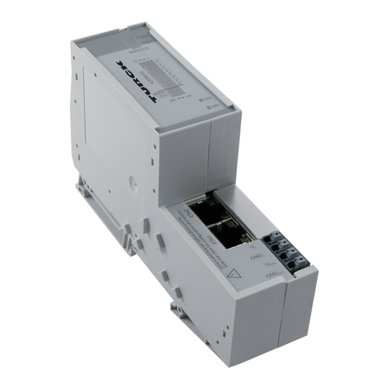
- Page 22 Setting of fieldbus address and bus terminating resistor (PROFIBUS-DP, DeviceNet, CANopen) via DIP-switches Service interface for commissioning with DTM (without PLC). Fig. 1: Gateway BL20-E-GW-EN Hans Turck GmbH & Co. KG | T +49 208 4952-0 | F +49 208 4952-264 | more@turck.com | www.turck.com...
- Page 23 Gateways with integrated power supply All standard gateways BL20-GWBR-××× as well as the BL20-gateways for DPV1 and Ethernet (BL20- GW-DPV1, BL20-GW-EN, BL20-GW-EN-IP, BL20-GW-EN-PN, BL20-PG-EN and BL20-PG-EN-IP) offer an integrated power supply unit for feeding the gateway and the connected I/O modules. It is not necessary to supply each individual module with a separate voltage.
- Page 24 Fig. 3: Electronics module in slice design (left) and in Block design (right) Hans Turck GmbH & Co. KG | T +49 208 4952-0 | F +49 208 4952-264 | more@turck.com | www.turck.com...
- Page 25 4.1.4 ECO electronics modules New ECONOMY modules with a high signal density and exceptionally low channel price expand the BL20 I/O bus terminal system. Depending on type, up to 16 digital inputs and outputs can be connected on only 13 mm. This high connection density considerably reduces the mounting width required for typical applications.
- Page 26 Fig. 5: Base module with tension clamp connection Fig. 6: Base module with screw connection Fig. 7: Base module in block design Hans Turck GmbH & Co. KG | T +49 208 4952-0 | F +49 208 4952-264 | more@turck.com | www.turck.com...
- Page 27 4.1.6 End plate An end plate on the right-hand side physically completes the BL20 station. An end bracket mounted into the end plate ensures that the BL20 station remains secure on the mounting rail even when subjected to vibration. Fig. 8: End plate 4.1.7 End bracket A second end bracket to the left of the gateway is necessary, as well as the one mounted into the...
- Page 28 Markers: for colored identification of connection levels of BL20 base modules. Dekafix connector markers: for numbering the mounting slots on BL20 base modules. Fig. 11: Marking material Hans Turck GmbH & Co. KG | T +49 208 4952-0 | F +49 208 4952-264 | more@turck.com | www.turck.com...
- Page 29 4.1.10 Shield connection gateway If the gateway is wired directly to the fieldbus, it is possible to shield the connection using a special gateway-shielding connection attachment (BS3511/KLBUE4-31.5). Fig. 12: Shield connection (gateway) 2020/09...
- Page 30 BL20 I/O System Hans Turck GmbH & Co. KG | T +49 208 4952-0 | F +49 208 4952-264 | more@turck.com | www.turck.com...
- Page 31 General Technical Data of BL20 Modules This chapter describes the general Technical data valid for all BL20 modules. The following chapters contain all information about the BL20 I/O, power supply and base modules as well as all module specific Technical data. NOTE The Technical data, diagnostic options as well as the parameterizing options for the gate- ways as well as all other fieldbus specific information are described in the bus-specific...
- Page 32 Fig. 14: Rear view of complete BL20 module in slice design 100.8 / 3.97 Fig. 15: Rear view of complete BL20 module in block design Hans Turck GmbH & Co. KG | T +49 208 4952-0 | F +49 208 4952-264 | more@turck.com | www.turck.com...
- Page 33 74.1 / 2.92 Fig. 16: Side view electronic module 12.6 / 0.49 Fig. 17: Rear view of electronic module in slice design 100.8 / 3.97 Fig. 18: Rear view of electronic module in block design 154.5 / 6.08 128.9 / 5.07 117.6 / 4.63 Fig.
- Page 34 Fig. 20: Base module with screw connection Fig. 21: Base module in slice design (top view) Fig. 22: Base module in block design (top view) Hans Turck GmbH & Co. KG | T +49 208 4952-0 | F +49 208 4952-264 | more@turck.com | www.turck.com...
- Page 35 5.1.4 Dimensions of the BL20-ECO modules 129.5 Fig. 23: Side view BL20-E-8D× 161.5 Fig. 24: Side view BL20-E-16D× Fig. 25: Rear view BL20-E-… complete module 2020/09...
- Page 36 Drop and topple Height of fall (weight < 10 kg) 1.0 m Height of fall (weight 10 to 40 kg) 0.5 m Hans Turck GmbH & Co. KG | T +49 208 4952-0 | F +49 208 4952-264 | more@turck.com | www.turck.com...
- Page 37 Technical data Test runs Device with packaging, electrically tested printed-circuit board. Electromagnetic compatibility (EMC) according to EN 50 50082-2 (Industry) Static electricity according to EN 61 000-4-2 – Discharge through air (direct) 8 kV – Relay discharge (indirect) 4 kV Electromagnetic HF fields according to 10 V/m EN 61 61000-4-3 and ENV 50 204...
- Page 38 Rated temperature Min. 75 ° C Min. 75 °C Pollution severity TOP connection technology Tension clamp or screw connection Screw connection Hans Turck GmbH & Co. KG | T +49 208 4952-0 | F +49 208 4952-264 | more@turck.com | www.turck.com...
- Page 39 Power Distribution Modules Power distribution (power feeding modules) Power Feeding modules distribute the required 24 VDC or 120/230 VAC field voltage to the I/O modules. They are necessary when groups of modules with different potentials are planned within a BL20 station, or if the rated supply voltage cannot be guaranteed. The adjoining power supply module and modules to the left are potentially isolated.
- Page 40 According to EN 61131-2 Maximum operating current I 10 A Voltage anomalies According to EN 61 000-4-11/ EN 61 131-2 Hans Turck GmbH & Co. KG | T +49 208 4952-0 | F +49 208 4952-264 | more@turck.com | www.turck.com...
- Page 41 6.2.2 Diagnostic and status messages The diagnostic functions monitor the supply voltages (system and field supply) supplied by the user for undervoltage. The diagnostic functions indicate errors via the ”DIA” LED and transmit the corre- sponding diagnostic information to the gateway. LED status displays Display Meaning...
- Page 42 Wiring diagram – 24 V DC Fig. 30: Wiring diagram BL20-P3T-SBB – 24 V DC Fig. 31: Wiring diagram BL20-P4x-SBBC Hans Turck GmbH & Co. KG | T +49 208 4952-0 | F +49 208 4952-264 | more@turck.com | www.turck.com...
- Page 43 Power Feeding module, 120/230 VDC, with diagnostics DANGER Dangerous contact voltage at earth faults Acute danger to life in case of incorrect grounding † Always observe the correct grounding of the system when using 120/230 V modules. Fig. 32: BL20-PF-120/230VAC-D Logik Galvanische Trennung der Diagnose U L...
- Page 44 Bit 1 Bit 0 No field voltage ”No field voltage” Monitoring of the external power supply to the field Hans Turck GmbH & Co. KG | T +49 208 4952-0 | F +49 208 4952-264 | more@turck.com | www.turck.com...
- Page 45 6.3.3 Base modules Fig. 34: Base module BL20-P3T-SBB Fig. 35: Base module BL20-P4T-SBBC with tension clamp connection BL20-P3T-SBB BL20-P4T-SBBC with screw connection BL20-P3S-SBB BL20-P4S-SBBC 6.3.4 Wiring diagram Fig. 36: Wiring diagram BL20-P3T-SBB 2020/09...
- Page 46 Error signals and diagnostic statuses are indicated via LEDs on the module. The corresponding diag- nostic information is transmitted to the gateway via diagnostic bits. 6.4.1 Module overview BL20-BR-24VDC-D Hans Turck GmbH & Co. KG | T +49 208 4952-0 | F +49 208 4952-264 | more@turck.com | www.turck.com...
- Page 47 Bus Refreshing module with diagnostics Fig. 38: BL20-BR-24VDC-D Diagnostics 5 V DC Logic 24 V DC Galvanic isolation of the diagnostics U L EMC Filter EMC Filter V DC Supply U sys V DC Supply U L Fig. 39: Block Diagram 6.5.1 Technical data Technical data...
- Page 48 Field power supply via Check the wiring to the field power supply. external power supply Check the external power supply unit. unit faulty Hans Turck GmbH & Co. KG | T +49 208 4952-0 | F +49 208 4952-264 | more@turck.com | www.turck.com...
- Page 49 Diagnostics This module has the following diagnostic data per channel: Bit 7 Bit 6 Bit 5 Bit 4 Bit 3 Bit 2 Bit 1 Bit 0 No field voltage Module bus voltage warning “Module bus voltage warning” Monitoring of the external power supply to the system U = 24 VDC.
- Page 50 24 V DC BL20-P3×-SBB-B without gateway power supply Module bus supply – – 24 V DC Field supply Fig. 43: Wiring diagram Hans Turck GmbH & Co. KG | T +49 208 4952-0 | F +49 208 4952-264 | more@turck.com | www.turck.com...
- Page 51 BL20-P4×-SBBC with gateway power supply 24 V DC BL20-P4×-SBBC-B without gateway power supply Module bus supply – – 24 V DC Field supply Fig. 44: Wiring diagram 2020/09...
- Page 52 Power Distribution Modules Hans Turck GmbH & Co. KG | T +49 208 4952-0 | F +49 208 4952-264 | more@turck.com | www.turck.com...
- Page 53 Digital Input Modules Digital input modules (DI) detect electrical high- and low-level values through the base module con- nections and transmit the corresponding digital value to the gateway via the module bus. The module bus electronics of the digital input modules are galvanically isolated from the field level via an optocoupler.
- Page 54 Input voltage, nominal value at 24 VDC Low level U - 30 V…+5 V High level U 11 V…30 V HIGH Input current Hans Turck GmbH & Co. KG | T +49 208 4952-0 | F +49 208 4952-264 | more@turck.com | www.turck.com...
- Page 55 Technical data Low level I 0…1.5 mA High level I 2…10 mA HIGH Input delay < 200 s < 200 s 2-wire initiators (Bero) can be connected with a permissible closed-circuit current of 1.5 mA 7.3.2 Base modules Fig. 47: Base module BL20-S3T-SBB Fig.
- Page 56 For DeviceNet, EtherNet/IP and Modbus TCP a detailed mapping table can be created with the Turck BL20 DTM in PACTware. Process data Value Meaning Digital input inactive Digital input active Hans Turck GmbH & Co. KG | T +49 208 4952-0 | F +49 208 4952-264 | more@turck.com | www.turck.com...
- Page 57 7.3.5 Diagnostic and status messages LED status displays Display Meaning Remedy Module bus communi- Check if more than two ad-joining electronics modules cation failure have been pulled. Check the supply of the module bus. No error messages or – diagnostics Green Status channel 1 = 1...
- Page 58 Input voltage, nominal value at 24 VDC High level U 0 V…+5 V Low level U > (U - 11 V) Input current Hans Turck GmbH & Co. KG | T +49 208 4952-0 | F +49 208 4952-264 | more@turck.com | www.turck.com...
- Page 59 Technical data High level U 1.3…6 mA HIGH Low level 0…1.2 mA Input delay < 200 s < 200 s 2-wire initiators (Bero) can be connected with a permissible closed-circuit current of 1.5 mA 7.4.2 Base modules Fig. 53: Base module BL20-S3T-SBB Fig.
- Page 60 For DeviceNet, EtherNet/IP and Modbus TCP a detailed mapping table can be created with the Turck BL20 DTM in PACTware. Process data Value Meaning Digital input inactive Digital input active Hans Turck GmbH & Co. KG | T +49 208 4952-0 | F +49 208 4952-264 | more@turck.com | www.turck.com...
- Page 61 7.4.5 Diagnostic and status messages LED status displays Display Meaning Remedy Module bus commu- Check if more than two ad-joining electronics nication failure modules have been pulled. Check the supply of the module bus. No error messages or – diagnostics Green Status channel 1 = 1...
- Page 62 Input voltage, nominal value at 120/230 VAC Low level U 0…20 VAC High level U 79…265 VAC HIGH Frequency range 47.5 Hz…63 Hz Hans Turck GmbH & Co. KG | T +49 208 4952-0 | F +49 208 4952-264 | more@turck.com | www.turck.com...
- Page 63 Technical data Input current Low level I 0…1 mA High level I 3…10 mA HIGH Input delay < 20 ms < 20 ms 7.5.2 Base modules Fig. 59: Base module BL20-S3T-SBB Fig. 60: Base module BL20-S4T-SBBC with tension clamp connection ...
- Page 64 For DeviceNet, EtherNet/IP and Modbus TCP a detailed mapping table can be created with the Turck BL20 DTM in PACTware. Process data Value Meaning Digital input inactive Digital input active Hans Turck GmbH & Co. KG | T +49 208 4952-0 | F +49 208 4952-264 | more@turck.com | www.turck.com...
- Page 65 7.5.5 Diagnostic and status messages LED status displays Display Meaning Remedy Module bus commu- Check if more than two ad-joining electronics nication failure modules have been pulled. Check the supply of the module bus. No error messages or – diagnostics Green Status channel 1 = 1...
- Page 66 Input voltage, nominal value at 24 VDC Low level U - 30 V…+5 V High level U 15 V…30 V HIGH Input current Hans Turck GmbH & Co. KG | T +49 208 4952-0 | F +49 208 4952-264 | more@turck.com | www.turck.com...
- Page 67 Technical data Low level I 0…1.5 mA High level I 2…10 mA HIGH Input delay < 200 s < 200 s 7.6.2 Base modules Fig. 65: Base module BL20-S4T-SBBS Fig. 66: Base module BL20-S6T-SBBSBB with tension clamp connection BL20-S4T-SBBS BL20-S6T-SBBSBB with screw connection ...
- Page 68 Digital Input Modules 7.6.3 Wiring diagram Fig. 67: Wiring diagram BL20-S4x-SBBS – – – – Fig. 68: Wiring diagram BL20-S6x-SBBSBB Hans Turck GmbH & Co. KG | T +49 208 4952-0 | F +49 208 4952-264 | more@turck.com | www.turck.com...
- Page 69 For DeviceNet, EtherNet/IP and Modbus TCP a detailed mapping table can be created with the Turck BL20 DTM in PACTware. Process data Value Meaning...
- Page 70 Input voltage, nominal value at 24 VDC High level U 0 V…+5 V Low level U > (U - 11 V) Input current Hans Turck GmbH & Co. KG | T +49 208 4952-0 | F +49 208 4952-264 | more@turck.com | www.turck.com...
- Page 71 Technical data High level U 1.3…6 mA HIGH Low level 0…1.2 mA Input delay < 200 s < 200 s 7.7.2 Base modules Fig. 71: Base module BL20-S4T-SBBS Fig. 72: Base module BL20-S6T-SBBSBB with tension clamp connection BL20-S4T-SBBS BL20-S6T-SBBSBB with screw connection ...
- Page 72 Digital Input Modules 7.7.3 Wiring diagram Fig. 73: Wiring diagram BL20-S4x-SBBS – – – – Fig. 74: Wiring diagram BL20-S6x-SBBSBB Hans Turck GmbH & Co. KG | T +49 208 4952-0 | F +49 208 4952-264 | more@turck.com | www.turck.com...
- Page 73 For DeviceNet, EtherNet/IP and Modbus TCP a detailed mapping table can be created with the Turck BL20 DTM in PACTware. Process data Value Meaning...
- Page 74 40 mA (input) NAMUR 1.74 mA switch-on threshold switch-off threshold 1.45 mA 0.08 mA switch-on threshold switch-off threshold 0.12 mA Hans Turck GmbH & Co. KG | T +49 208 4952-0 | F +49 208 4952-264 | more@turck.com | www.turck.com...
- Page 75 Technical data switch-on threshold 6.2 mA 5.9 mA switch-off threshold Isolation voltage (module bus/ field) 2500 VDC (field supply/ FE) 1000 VDC 7.8.2 Base modules Fig. 77: Base module BL20-S4T-SBBS with tension clamp connection BL20-S4T-SBBS with screw connection BL20-S4S-SBBS 7.8.3 Wiring diagram...
- Page 76 Status channel 2 = 0 Green Status channel 3 = 1 Short circuit or wire break Status channel 3 = 0 Hans Turck GmbH & Co. KG | T +49 208 4952-0 | F +49 208 4952-264 | more@turck.com | www.turck.com...
- Page 77 NOTE The actual configuration files (GSD-, GSDML-, EDS-files) with the new parameters can be found under www.turck.com. If you use older configuration files with old parameter texts (issue date before April 2014), then you can find a cross reference list in the manual's appendix (see...
- Page 78 Activate wire break diagnostics Bit 6 Bit 6 Bit 6 Input on diagnostic Bit 7 Bit 7 Bit 7 Substitute value Hans Turck GmbH & Co. KG | T +49 208 4952-0 | F +49 208 4952-264 | more@turck.com | www.turck.com...
- Page 79 Parameters Value Invert digital input 0 = no 1 = yes Activate input filter 0 = no, filter time = 0.25 ms 1 = yes, filter time = 2.5 ms Activate overcurrent monitoring 0 = no 1 = yes Activate overcurrent diagnostics 0 = no 1 = yes Activate wire break monitoring...
- Page 80 High level U 11 V…30 V HIGH Input current Low level I -1…1.5 mA High level I 2…5 mA HIGH Hans Turck GmbH & Co. KG | T +49 208 4952-0 | F +49 208 4952-264 | more@turck.com | www.turck.com...
- Page 81 Technical data Input delay < 100 s < 200 s Isolation voltage Module bus/ channels 500 V 7.9.2 Wiring diagram 24 V DC Fig. 81: Wiring diagram 24 V DC Fig. 82: Wiring diagram with sensor supply 2020/09...
- Page 82 Status channel 1 = 1 Status channel 1 = 0 … … … Green Status channel 8 = 1 Status channel 8 = 0 Hans Turck GmbH & Co. KG | T +49 208 4952-0 | F +49 208 4952-264 | more@turck.com | www.turck.com...
- Page 83 7.10 Digital input module, 16DI, 24 VDC, positive switching (sinking) Fig. 83: BL20-16DI-24VDC-P Logic Galvanic isolation 24 V DC Filter 16 Filter 1 Field Fig. 84: Block Diagram 7.10.1 Technical data Technical data Designation BL20-16DI-24VDC-P Number of channels Nominal voltage from supply terminal U 24 VDC 40 mA Nominal current from supply terminal I...
- Page 84 7.1.1 Base modules Fig. 85: Base module BL20-B3T-SBB Fig. 86: Base module BL20-B4T-SBBC with tension clamp connection BL20-B3T-SBB BL20-B4T-SBBC Hans Turck GmbH & Co. KG | T +49 208 4952-0 | F +49 208 4952-264 | more@turck.com | www.turck.com...
- Page 85 For DeviceNet, EtherNet/IP and Modbus TCP a detailed mapping table can be created with the Turck BL20 DTM in PACTware. Process data Value Meaning...
- Page 86 Status channel 16 = 0 NOTE The numbering of the channel LEDs corresponds to the numbering of the connectors at the base module. Hans Turck GmbH & Co. KG | T +49 208 4952-0 | F +49 208 4952-264 | more@turck.com | www.turck.com...
- Page 87 7.11 Digital input module, BL20 Economy, 16 DI, 24 VDC, positive switching (sinking) Fig. 89: BL20-E-16DI-24VDC-P 16 x Logic GND (5 V DC) 5 V DC (24 V DC) . . . Filter Filter Filter Field Fig. 90: Block Diagram 7.11.1 Technical data Technical data...
- Page 88 VN 01-02 < 300 µs VN 02-00 < 60 µs Isolation voltage Module bus/ channels 500 V Weight 65 g Hans Turck GmbH & Co. KG | T +49 208 4952-0 | F +49 208 4952-264 | more@turck.com | www.turck.com...
- Page 89 7.11.2 Wiring diagram (24 V DC) Fig. 91: Wiring diagram (24 V DC) Fig. 92: Wiring diagram with sensor supply 2020/09...
- Page 90 For DeviceNet, EtherNet/IP and Modbus TCP a detailed mapping table can be created with the Turck BL20 DTM in PACTware. Process data Value Meaning Digital input inactive Digital input active Hans Turck GmbH & Co. KG | T +49 208 4952-0 | F +49 208 4952-264 | more@turck.com | www.turck.com...
- Page 91 7.11.4 Diagnostic and status messages LED status displays Display Meaning Remedy Module bus communi- Check if more than two ad-joining electronics modules cation failure have been pulled. Check the supply of the module bus. No error messages or – diagnostics Green Status channel 1 = 1 Status channel 1 = 0...
- Page 92 Input voltage, nominal value at 24 VDC Low level U > (U - 5 V) High level U < (U - 11 V) HIGH Input current Hans Turck GmbH & Co. KG | T +49 208 4952-0 | F +49 208 4952-264 | more@turck.com | www.turck.com...
- Page 93 Technical data Low level I -1…1.5 mA High level I 2…5 mA HIGH Input delay < 20 s < 125 s Isolation voltage Module bus/ channels 500 V Weight 65 g 7.12.2 Wiring diagram (24 V DC) Fig. 95: Wiring diagram 2020/09...
- Page 94 For DeviceNet, EtherNet/IP and Modbus TCP a detailed mapping table can be created with the Turck BL20 DTM in PACTware. Process data Value Meaning Digital input inactive Digital input active Hans Turck GmbH & Co. KG | T +49 208 4952-0 | F +49 208 4952-264 | more@turck.com | www.turck.com...
- Page 95 7.12.4 Diagnostic and status messages LED status displays Display Meaning Remedy Module bus communi- Check if more than two ad-joining electronics modules cation failure have been pulled. Check the supply of the module bus. No error messages or – diagnostics Green Status channel 1 = 1 Status channel 1 = 0...
- Page 96 Nominal current from module bus I < 45 mA Power loss of the module, typical < 4,2 W Input voltage, nominal value at 24 VDC Hans Turck GmbH & Co. KG | T +49 208 4952-0 | F +49 208 4952-264 | more@turck.com | www.turck.com...
- Page 97 Technical data Low level U - 30 V…+5 V High level U 15 V…30 V HIGH Input current Low level I < 1.5 mA High level I 2…10 mA HIGH Input delay < 200 s < 200 s 7.13.2 Base modules Fig.
- Page 98 For DeviceNet, EtherNet/IP and Modbus TCP a detailed mapping table can be created with the Turck BL20 DTM in PACTware. Process data Value Meaning Digital input inactive Digital input active Hans Turck GmbH & Co. KG | T +49 208 4952-0 | F +49 208 4952-264 | more@turck.com | www.turck.com...
- Page 99 7.13.5 Diagnostic and status messages LED status displays Display Meaning Remedy Module bus commu- Check if more than two ad-joining electronics modules nication failure have been pulled. Check the supply of the module bus. No error messages or – diagnostics Green Status channel 1 = 1 Status channel 1 = 0...
- Page 100 Digital Input Modules Hans Turck GmbH & Co. KG | T +49 208 4952-0 | F +49 208 4952-264 | more@turck.com | www.turck.com...
- Page 101 Analog Input Modules Analog input modules (AI) detect standard electrical signals at the connections of the base modules, digitalize them and transmit the corresponding measurement values to the gateway via the internal module bus. The module bus electronics of the analog input modules are galvanically isolated from the field level via an optocoupler.
- Page 102 Analog Input Modules 8.0.3 Module overview Module Number of channels BL20-1AI-I(0/4…20MA) BL20-2AI-I(0/4…20MA) BL20-1AI-U(-10/0...+10VDC) BL20-2AI-U(-10/0...+10VDC) BL20-2AI-PT/NI-2/3 BL20-2AI-THERMO-PI BL20-4AI-U/I BL20-E-8AI-U/I-4PT/NI BL20-2AIH-I BL20-E-4AI-TC Hans Turck GmbH & Co. KG | T +49 208 4952-0 | F +49 208 4952-264 | more@turck.com | www.turck.com...
- Page 103 Analog input module, 1AI, 0/4...20 mA Fig. 100: BL20-1AI-I(0/4…20MA) Logic Galvanic isolation 24 V DC A/D Converter Reference R < 125 O Sensor power supply max. 250 mA Field Fig. 101: Block Diagram 8.1.1 Technical data Technical data Designation BL20-1AI-I(0/4…20MA) Number of channels Nominal voltage from supply terminal 24 VDC...
- Page 104 Fig. 102: Base module BL20-S3T-SBB Fig. 103: Base module BL20-S4T-SBBS with tension clamp connection BL20-S3T-SBB BL20-S4T-SBBS with screw connection BL20-S3S-SBB BL20-S4S-SBBS Hans Turck GmbH & Co. KG | T +49 208 4952-0 | F +49 208 4952-264 | more@turck.com | www.turck.com...
- Page 105 8.1.3 Wiring diagram Fig. 104: 2-wire sensor with sensor supply via base module BL20-S4×-SBBS U/I+ Fig. 105: 3-wire sensor with sensor supply via base module BL20-S4×-SBBS U/I + U/I - Fig. 106: 4-wire sensor with sensor supply via base module BL20-S4×-SBBS 2020/09...
- Page 106 Check if more than two ad-joining electronics nication failure modules have been pulled. Check the supply of the module bus. No error messages or – diagnostics Hans Turck GmbH & Co. KG | T +49 208 4952-0 | F +49 208 4952-264 | more@turck.com | www.turck.com...
- Page 107 4…20 mA (I < 3 mA) 8.1.6 Module parameters NOTE Due to a product actualization, the parameter texts of the Turck I/O-products have been revised. The actual configuration files (GSD-, GSDML-, EDS-files) with the new parameters can be found under www.turck.com.
- Page 108 A detailed description of the measurement value representation for the analog input modules in 16 or 12 bit can be found in the Appendix, s. 493. Hans Turck GmbH & Co. KG | T +49 208 4952-0 | F +49 208 4952-264 | more@turck.com | www.turck.com...
- Page 109 Analog input module, 2AI, 0/4...20mA Fig. 108: BL20-2AI-I(0/4…20MA) Logic Galvanic isolation 24 V DC A/D Converter Reference + Multiplexer R < 125 O Sensor power supply max. 250 mA Field Fig. 109: Block Diagram 8.2.1 Technical data Technical data Designation BL20-2AI-I(0/4…20MA) Number of channels Nominal voltage from...
- Page 110 Fig. 110: Base module BL20-S3T-SBB Fig. 111: Base module BL20-S4T-SBBS with tension clamp connection BL20-S3T-SBB BL20-S4T-SBBS with screw connection BL20-S3S-SBB BL20-S4S-SBBS Hans Turck GmbH & Co. KG | T +49 208 4952-0 | F +49 208 4952-264 | more@turck.com | www.turck.com...
- Page 111 8.2.3 Wiring diagram Fig. 112: 2-wire sensor with sensor supply via base module BL20-S4×-SBBS U/I+ U/I+ Fig. 113: 3-wire sensor with sensor supply via base module BL20-S4×-SBBS U/I + U/I + U/I - U/I - Fig. 114: 4-wire sensor with external sensor supply BL20-S3×-SBB 2020/09...
- Page 112 Bit 6 Bit 5 Bit 4 Bit 3 Bit 2 Bit 1 Bit 0 Wire break Measured value out of range Hans Turck GmbH & Co. KG | T +49 208 4952-0 | F +49 208 4952-264 | more@turck.com | www.turck.com...
- Page 113 8.2.6 Module parameters NOTE Due to a product actualization, the parameter texts of the Turck I/O-products have been revised. The actual configuration files (GSD-, GSDML-, EDS-files) with the new parameters can be found under www.turck.com. If you use older configuration files with old parameter texts (issue date before April 2014),...
- Page 114 Bit 4 reserved Bit 5 Bit 13 Bit 5 Bit 6 Bit 14 Bit 6 Bit 7 Bit 15 Bit 7 Hans Turck GmbH & Co. KG | T +49 208 4952-0 | F +49 208 4952-264 | more@turck.com | www.turck.com...
- Page 115 The default values are written in bold Parameters Value Measurement range 0 = 0…20 mA 1 = 4…20 mA 0 = 15 bit + sign Data format 1 = 12 bit (left-justified) Deactivate all diagnostics 0 = no 1 = yes Deactivate channel 0 = no 1 = yes...
- Page 116 Power loss of module, typical < 1 W Input voltage -10/0…+10 V Maximum input voltage 35 V continuous 98,5 k Input resistance (burden) Hans Turck GmbH & Co. KG | T +49 208 4952-0 | F +49 208 4952-264 | more@turck.com | www.turck.com...
- Page 117 Technical data Cutoff frequency (-3 dB) 200 Hz Basic error at 23 °C / 73.4 °F < 0,2 % Repeatability 0,05 % 300 ppm/°C from end value Temperature coefficient Resolution of the A/D converter gradual approximation Measuring principle Delta Sigma Measured value 16 bit signed integer /12 bit signed integer left-justi- representation...
- Page 118 Fig. 120: 3-wire sensor with sensor supply via base module BL20-S4×-SBBS U/I + U/I - Fig. 121: 4-wire sensor with sensor supply via base module BL20-S4×-SBBS Hans Turck GmbH & Co. KG | T +49 208 4952-0 | F +49 208 4952-264 | more@turck.com | www.turck.com...
- Page 119 For DeviceNet, EtherNet/IP and Modbus TCP a detailed mapping table can be created with the TURCK BL20 DTM in PACTware. Process data Meaning AI1 LSB...
- Page 120 Overvoltage: (U > 10,1 V); Undervoltage: (U < -10,1 V) at-10…+10 V (U < -0,1 V) at 0…10 V Hans Turck GmbH & Co. KG | T +49 208 4952-0 | F +49 208 4952-264 | more@turck.com | www.turck.com...
- Page 121 8.3.6 Module parameters NOTE Due to a product actualization, the parameter texts of the Turck I/O-products have been revised. The actual configuration files (GSD-, GSDML-, EDS-files) with the new parameters can be found under www.turck.com. If you use older configuration files with old parameter texts (issue date before April 2014),...
- Page 122 BL20-2AI-U(-10/0...+10VDC) Number of channels Nominal voltage from 24 VDC supply terminal U 12 mA Nominal current from supply terminal I Hans Turck GmbH & Co. KG | T +49 208 4952-0 | F +49 208 4952-264 | more@turck.com | www.turck.com...
- Page 123 Technical data 35 mA Nominal current from module bus I Power loss of the module, typical < 1 W Input voltage -10/0…+10 V Maximum input voltage 35 V continuous 98,5 k Input resistance (burden) 50 Hz Cutoff frequency (-3 dB) Basic error at 23 °C / 73.4 °F <...
- Page 124 Fig. 128: 3-wire sensor with sensor supply via base module BL20-S4×-SBBS U/I + U/I + U/I - U/I - Fig. 129: 4-wire sensor with external sensor supply BL20-S3×-SBB Hans Turck GmbH & Co. KG | T +49 208 4952-0 | F +49 208 4952-264 | more@turck.com | www.turck.com...
- Page 125 For DeviceNet, EtherNet/IP and Modbus TCP a detailed mapping table can be created with the TURCK BL20 DTM in PACTware. Process data Meaning AI1 LSB...
- Page 126 If you use older configuration files with old parameter texts (issue date before April 2014), then you can find a cross reference list in the manual's appendix (see Cross reference list parameters (page 523)). Hans Turck GmbH & Co. KG | T +49 208 4952-0 | F +49 208 4952-264 | more@turck.com | www.turck.com...
- Page 127 Standard PROFIBUS Parameters Byte Word PROFINET oriented oriented Channel 1 Bit 0 Bit 0 Bit 0 Measurement range Bit 1 Bit 1 Bit 1 Data format Bit 2 Bit 2 Bit 2 Deactivate all diagnostics Bit 3 Bit 3 Bit 3 Deactivate channel Bit 4 Bit 4...
- Page 128 Nominal current from module bus I Power loss of the module, typical < 1 W Measurement current < 1 mA Destruction limit > 30 VDC Hans Turck GmbH & Co. KG | T +49 208 4952-0 | F +49 208 4952-264 | more@turck.com | www.turck.com...
- Page 129 Technical data Platinum sensors According to DIN IEC 751 Nickel sensors According to EN 43 760 0,1% Offset error Linearity < 0,1 % Basic error at 23 °C / 73.4 °F < 0,2 % from end value Repeatability 0,05 % 300 ppm/°C from end value Temperature coefficient 130 ms per channel...
- Page 130 BL20-S3S-SBB BL20-S4S-SBBS 8.5.3 Wiring diagram 2-wire measurement: Fig. 134: Wiring diagram BL20-S3x-SBB 3-wire measurement: Fig. 135: Wiring diagram BL20-S4x-SBBS Hans Turck GmbH & Co. KG | T +49 208 4952-0 | F +49 208 4952-264 | more@turck.com | www.turck.com...
- Page 131 For DeviceNet, EtherNet/IP and Modbus TCP a detailed mapping table can be created with the TURCK BL20 DTM in PACTware. Process data Meaning AI1 LSB...
- Page 132 In 3-wire measurement with PT100- sensor and at temperatures of below -177 °C, the module can not distinguish between short-circuit and wire break. In this case a ”short- circuit”- diagnostic is generated. Hans Turck GmbH & Co. KG | T +49 208 4952-0 | F +49 208 4952-264 | more@turck.com | www.turck.com...
- Page 133 8.5.6 Module parameters NOTE Due to a product actualization, the parameter texts of the Turck I/O-products have been revised. The actual configuration files (GSD-, GSDML-, EDS-files) with the new parameters can be found under www.turck.com. If you use older configuration files with old parameter texts (issue date before April 2014),...
- Page 134 1 = 12 bit (left-justified) Deactivate all diagnostics 0 = no 1 = yes 0 = no Deactivate channel 1 = yes Hans Turck GmbH & Co. KG | T +49 208 4952-0 | F +49 208 4952-264 | more@turck.com | www.turck.com...
- Page 135 Parameters Value RTD type 0000 = Pt100, -200…850 °C 0001 = Pt100, -200…150 °C 0010 = Ni100, -60…250 °C 0011 = Ni100, -60…150 °C 0100 = Pt200, -200…850 °C 0101 = Pt200, -200…150 °C 0110 = Pt500, -200…850 °C 0111 = Pt500, -200…150 °C 1000 = Pt1000, -200…850 °C 1001 = Pt1000, -200…150 °C 1010 = Ni1000, -60…250 °C...
- Page 136 Fig. 136: BL20-2AI-THERMO-PI Logic Galvanic isolation 24 V DC D/A Converter Reference Channel selection Base terminal Field Fig. 137: Block Diagram Hans Turck GmbH & Co. KG | T +49 208 4952-0 | F +49 208 4952-264 | more@turck.com | www.turck.com...
- Page 137 8.6.1 Technical data Technical data Designation BL20-2AI-THERMO-PI Number of channels Nominal voltage from supply terminal U 24 VDC 30 mA Nominal current from supply terminal I 45 mA Nominal current from module bus I Power loss of the module, typical <...
- Page 138 BL20-S4S-SBBS-CJ 8.6.3 Wiring diagram Cold junction compensation in base module – PT1000 PT1000 – Fig. 139: Wiring diagram BL20-S4×-SBBS-CJ Hans Turck GmbH & Co. KG | T +49 208 4952-0 | F +49 208 4952-264 | more@turck.com | www.turck.com...
- Page 139 Basic errors and repeat accuracies Thermocouple Temperature range/ °C Basic error at 23°C / % of positive end value type K -200…1370 ± 0,2 Type J -210…1200 ± 0,2 Type B 500…1820 ± 0,2 type N -150…1300 ± 0,2 Type E -180…1000 ±...
- Page 140 Wire break range Diagnostics Meaning Measured value out of range threshold: 1 % of the positive measurement range end value Hans Turck GmbH & Co. KG | T +49 208 4952-0 | F +49 208 4952-264 | more@turck.com | www.turck.com...
- Page 141 T when the temperature falls below -271.6 °C. 8.6.6 Module parameters NOTE Due to a product actualization, the parameter texts of the Turck I/O-products have been revised. The actual configuration files (GSD-, GSDML-, EDS-files) with the new parameters can be found under www.turck.com.
- Page 142 1 = 12 bit (left-justified) 0 = no Deactivate all diagnostics 1 = yes Deactivate channel 0 = no 1 = yes Hans Turck GmbH & Co. KG | T +49 208 4952-0 | F +49 208 4952-264 | more@turck.com | www.turck.com...
- Page 143 0000 = Typ K, -270…1370 °C Thermocouple type 0001 = Type B, +100…1820 °C 0010 = Type E, -270…1000 °C 0011 = Type J, -210…1200 °C 0100 = Type N, -270…1300 °C 0101 = Type R, -50…1760 °C 0110 = Type S, -50…1540 °C 0111 = Type T, -270…400 °C 1000 = ±50 mV 1001 = ±100 mV...
- Page 144 A/D converter Reference + multiplexer R < 62 O in current mode R > 98,5 kO in voltage mode field Hans Turck GmbH & Co. KG | T +49 208 4952-0 | F +49 208 4952-264 | more@turck.com | www.turck.com...
- Page 145 8.7.1 Technical data Technical data Designation BL20-4AI-U/I Number of channels Nominal voltage from supply terminal U 24 VDC 0 mA Nominal current from supply terminal I 50 mA Nominal current from module bus I Power loss of the module, typical <...
- Page 146 BR/PF BR/PF Klemme 13 Klemme 13 Fig. 143: 2-wire sensors with sensor supply via UL or BR/PF-module, base module BL20-S6×-SBCSBC Hans Turck GmbH & Co. KG | T +49 208 4952-0 | F +49 208 4952-264 | more@turck.com | www.turck.com...
- Page 147 U/I+ U/I+ – – Kanal 1 Kanal 2 U L bzw. U L bzw. BR/PF BR/PF Klemme 13 Klemme 13 U/I+ U/I+ – – Kanal 3 Kanal 4 U L bzw. U L bzw. BR/PF BR/PF Klemme 13 Klemme 13 Fig.
- Page 148 Bit 6 Bit 5 Bit 4 Bit 3 Bit 2 Bit 1 Bit 0 Wire break Measured value out of range Hans Turck GmbH & Co. KG | T +49 208 4952-0 | F +49 208 4952-264 | more@turck.com | www.turck.com...
- Page 149 8.7.6 Module parameters NOTE Due to a product actualization, the parameter texts of the Turck I/O-products have been revised. The actual configuration files (GSD-, GSDML-, EDS-files) with the new parameters can be found under www.turck.com. If you use older configuration files with old parameter texts (issue date before April 2014),...
- Page 150 Bit 5 Bit 5 Bit 5 Data representation Bit 6 Bit 6 Bit 6 Bit 7 Bit 7 Bit 7 Hans Turck GmbH & Co. KG | T +49 208 4952-0 | F +49 208 4952-264 | more@turck.com | www.turck.com...
- Page 151 The default values are written in bold Parameters Value Measurement range 0 = 0…10 V/ 0…20 mA 1 = -10…+10 V/ 4…20 mA 0 = 15 bit + sign Data format 1 = 12 bit (left-justified) Deactivate all diagnostics 0 = no 1 = yes Deactivate channel 0 = no...
- Page 152 Fig. 146: BL20-E-8AI-U/I-4PT/NI logic galvanic isolation 24 V DC A/D converter Reference + multiplexer field Fig. 147: Block Diagram Hans Turck GmbH & Co. KG | T +49 208 4952-0 | F +49 208 4952-264 | more@turck.com | www.turck.com...
- Page 153 8.8.1 Technical data Technical data Designation BL20-E-8AI-U/I-4PT/NI Number of channels 8 (U/I) /4 (Pt/Ni/R) Nominal voltage from supply terminal U 24 VDC (18 VDC…30 VDC) Nominal current from typ. 35 mA (without measurement signal) supply terminal I 30 mA Nominal current from module bus I Power loss of module, typical <...
- Page 154 > 30 VDC Cutoff frequency f 1.5 Hz Basic error 0.2 % (nominal range at 23 °C) Temperature coefficient 200 ppm/ °C Hans Turck GmbH & Co. KG | T +49 208 4952-0 | F +49 208 4952-264 | more@turck.com | www.turck.com...
- Page 155 8.8.2 Wiring diagram The terminal assignment depends on the sensor type. PT/NI 2-Leiter 2-Leiter 3-Leiter – é é – I – I – – é é – I – I – – é é – I – I – – é...
- Page 156 BL20 system are automatically BL20-Gateway E-8AI sensor on the same GND potential. AI – AI + Fig. 151: 2-wire-sensor (U/I) Hans Turck GmbH & Co. KG | T +49 208 4952-0 | F +49 208 4952-264 | more@turck.com | www.turck.com...
- Page 157 For DeviceNet, EtherNet/IP and Modbus TCP a detailed mapping table can be created with the TURCK BL20 DTM in PACTware. Process data Meaning AI1 LSB...
- Page 158 Green channel is in overrange flashing 4 Hz Green channel is in under- flashing range 0.5 Hz channel inactive Hans Turck GmbH & Co. KG | T +49 208 4952-0 | F +49 208 4952-264 | more@turck.com | www.turck.com...
- Page 159 Please observe the module’s maximum input voltage! 8.8.5 Module parameters NOTE Due to a product actualization, the parameter texts of the Turck I/O-products have been revised. The actual configuration files (GSD-, GSDML-, EDS-files) with the new parameters can be found under www.turck.com.
- Page 160 Bit 5 Bit 6 Bit 14 Bit 6 Data format Bit 7 Bit 15 Bit 7 Deactivate all diagnostics … Hans Turck GmbH & Co. KG | T +49 208 4952-0 | F +49 208 4952-264 | more@turck.com | www.turck.com...
- Page 161 Standard PROFIBUS Parameters Byte Word PROFINET oriented oriented Channel 7 Bit 0 Bit 0 Bit 0 Mode Bit 1 Bit 1 Bit 1 Bit 2 Bit 2 Bit 2 Bit 3 Bit 3 Bit 3 Bit 4 Bit 4 Bit 4 Bit 5 Bit 5 Bit 5...
- Page 162 0 = 15 bit + sign 1 = 12 bit (left-justified) Deactivate all diagnostics 0 = no 1 = yes Hans Turck GmbH & Co. KG | T +49 208 4952-0 | F +49 208 4952-264 | more@turck.com | www.turck.com...
- Page 163 8.8.6 Process input data For input-parameterization as Pt-/Ni-or R, the measurement value can be found in the channel with the lower number of the used channels (K1, K3, K5, K7). Chan- Byte 1 Byte 0 Byte 3 Byte 2 Byte 5 Byte 4 Byte 7 Byte 6...
- Page 164 -0.1 mA atDIA 0000 Measured value out of range < -0.2 mA at DIA 0000 Measured value out of range Hans Turck GmbH & Co. KG | T +49 208 4952-0 | F +49 208 4952-264 | more@turck.com | www.turck.com...
- Page 165 4…20 mA unipolar Diagnostics dec. hex. current value = (dec. value × 4,883 × 10 ) + 4 mA > 20.2000 mA atDIA 32767 7FFF Measured value out of range 20,1000 mA at DIA 32767 7FFF Measured value out of range 20.0000 mA 32767...
- Page 166 -2048 × 16 800× Measured value out of range < -10.1000 V atDIA -2048 × 16 800× Measured value out of range Hans Turck GmbH & Co. KG | T +49 208 4952-0 | F +49 208 4952-264 | more@turck.com | www.turck.com...
- Page 167 0…10 V unipolar Diagnostics dec. hex. Voltage value U = (dec. value/ 16 × 2,442 × 10 > 10.1000 V atDIA 4095 × 16 FFF× Measured value out of range 10,0500 V at DIA 4095 × 16 FFF× Measured value out of range 10.0000 V 4095 ×...
- Page 168 Measured value out of range 3.0000 mA atDIA 000× Wire break < 2.9000 mA at DIA 000× Wire break Hans Turck GmbH & Co. KG | T +49 208 4952-0 | F +49 208 4952-264 | more@turck.com | www.turck.com...
- Page 169 8.8.8 Extended Range - value representation for voltage/current 16-bit representation -10…10 V bipolar Diagnostics dec. hex. Voltage value U = (dec. value × 3.617 × 10 11,851490 V Overflow 32767 7FFF 11,7593 V atDIA 32512 7F00 Measured value out of range 11.7589 V out of range...
- Page 170 Overflow/ -0,050 V at DIA Underflow 0000 underflow, OUFL Overflow/ < -0.100 V at DIA 0000 underflow, OUFL Hans Turck GmbH & Co. KG | T +49 208 4952-0 | F +49 208 4952-264 | more@turck.com | www.turck.com...
- Page 171 0…20 mA bipolar Diagnostics dec. hex. Current value I = (dec. value × 7.234 × 10 ) mA 23.70298 mA Overflow 32767 7FFF 23.51852 mA atDIA 32512 7F00 Measured value out of range 23.517795 mA out of range 32511 7EFF ...
- Page 172 1.185185 -4864 ED00 1,184606 mA Underflow at DIA -4865 ECFF Measured value out of range 0.0000 mA -6912 E500 Hans Turck GmbH & Co. KG | T +49 208 4952-0 | F +49 208 4952-264 | more@turck.com | www.turck.com...
- Page 173 12-bit-representation (left-justified) The representation of the 12 bit values corresponds to that of the 16 bit values. Only bits 0 to 3 are set to ”0”. Diagnostic data are not mapped to the process data. -10…10 V bipolar Diagnostics dec. hex.
- Page 174 1 × 16 0010 0.00000 V 0000 -0,050 V Underflow atDIA 0000 Overflow/underflow, OUFL < -0.100 V at DIA 0000 Overflow/underflow, OUFL Hans Turck GmbH & Co. KG | T +49 208 4952-0 | F +49 208 4952-264 | more@turck.com | www.turck.com...
- Page 175 0…20 mA bipolar Diagnostics dec. hex. Current value I = (dec. value/16 × 0,01157) mA 23.6921 mA Overflow 2047 × 16 7FF0 23.51852 mA atDIA 2032 × 16 7F00 Measured value out of range 23.5069 mA out of range 2031 × 16 7EF0 ...
- Page 176 ECF0 1,1759 mA Measured value out of -305 × 16 Underflow range 0,000 mA -432 × 16 E500 Hans Turck GmbH & Co. KG | T +49 208 4952-0 | F +49 208 4952-264 | more@turck.com | www.turck.com...
- Page 177 8.8.9 Value representation for process automation (NE 43) for voltage/current 16-bit representation The hexadecimal value transmitted by the module has to be interpreted as decimal value, which corresponds, if multiplied with a defined factor, to the analog value. Example: Input current: 15.02 mA Process value: dec.
- Page 178 0001 0.000 V 0000 - 0,05 V Underflow atDIA 0000 Overflow/underflow, OUFL < -0.10 V at DIA 0000 Overflow/underflow, OUFL Hans Turck GmbH & Co. KG | T +49 208 4952-0 | F +49 208 4952-264 | more@turck.com | www.turck.com...
- Page 179 0…20 mA unipolar Diagnostics dec. hex. Current value I = (dec. value × 0,001) mA 22.000 mA Overflow atDIA 22000 55F0 Overflow/underflow, OUFL 21,999 mA at DIA 21999 55EF Overflow/underflow, OUFL 21.001 mA atDIA 21001 5209 Measured value out of 21.000 mA out of range 21000...
- Page 180 2.001 mA atDIA 2001 07D1 Wire break 2,000 mA at DIA 2000 07D0 Wire break 0.000 mA 0000 0000 Hans Turck GmbH & Co. KG | T +49 208 4952-0 | F +49 208 4952-264 | more@turck.com | www.turck.com...
- Page 181 12-bit-representation (left-justified) The ”12-bit-representation (left-justified)” in process automation corresponds to the 16-bit-repre- sentation in which the lower 4 bits of the analog value are overwritten with diagnostic data. -10…10 V bipolar Diagnostics dec. hex. Voltage value U = (dec. value × 0,001) V ...
- Page 182 001× 0,0000 V 000× -0,05 V Underflow atDIA 000× Overflow/underflow, OUFL < -0.1 V at DIA 000× Overflow/underflow, OUFL Hans Turck GmbH & Co. KG | T +49 208 4952-0 | F +49 208 4952-264 | more@turck.com | www.turck.com...
- Page 183 0…20 mA unipolar Diagnostics dec. hex. Current value I = (dec. value/16 × 0,001) mA 22.000 mA Overflow atDIA 22000 55F× Overflow/underflow, OUFL 21,984 mA at DIA 21984 55E× Overflow/underflow, OUFL 21.024 mA 21024 522× 21.008 mA out of range atDIA 21008...
- Page 184 2.001 mA atDIA 2001 07D× Wire break 2.000 mA at DIA 2000 07D× Wire break 0.000 mA 0000 000× Hans Turck GmbH & Co. KG | T +49 208 4952-0 | F +49 208 4952-264 | more@turck.com | www.turck.com...
- Page 185 8.8.10 Standard value representation for Pt-/ Ni- and resistance measurement Wire break and short circuit diagnostic in Pt-/Ni-measurement Wire break (WB) if resistance = end value of measurement range Short circuit (SC) if resistance = loop resistance < 5 ...
- Page 186 FDA8 Measured value out of range -101.0 % -60,60 °C at DIA -600 FDA8 Measured value out of range Hans Turck GmbH & Co. KG | T +49 208 4952-0 | F +49 208 4952-264 | more@turck.com | www.turck.com...
- Page 187 Measurement range, Ni -60…150 °C Transmitted value Ni100, Ni1000 dec. hex. temperature T = (dec. value × 0,01) °C 151,50 °C 101.0 % at DIA 15000 3A98 Measured value out of range 150,70 °C at DIA 100.5 % 15000 3A98...
- Page 188 4000 399,988 49.998 % 16383 3FFF … … … … 0.02441 0.003 % 0001 0,0000 0000 Hans Turck GmbH & Co. KG | T +49 208 4952-0 | F +49 208 4952-264 | more@turck.com | www.turck.com...
- Page 189 Measurement range, R Transmitted value 0…2000 dec. hex. = (dec. value × 0,061037) Resistance R 2020,0 101.0 % atDIA 32767 7FFF Measured value out of range 2010,0 100.5 % atDIA 32767 7FFF Measured value out of range 2000,0 ...
- Page 190 Measured value out of range -202,0 °C -101.0 % at DIA -2000 × 16 830× Measured value out of range Hans Turck GmbH & Co. KG | T +49 208 4952-0 | F +49 208 4952-264 | more@turck.com | www.turck.com...
- Page 191 Measurement range, Ni -60…250 °C Transmitted value Ni100, Ni1000, Ni100TK5000 dec. hex. temperature T = (dec. value/16 × 0,5) °C 252,50 °C 101.0 % atDIA 500 × 16 1F4× Measured value out of range 251,20 °C 100.5 % atDIA 500 ×...
- Page 192 7FFF … … … … 0,09768 0.024 % 1 × 16 001× 0,0000 0 × 16 000× Hans Turck GmbH & Co. KG | T +49 208 4952-0 | F +49 208 4952-264 | more@turck.com | www.turck.com...
- Page 193 Measurement range, R Transmitted value 0…800 dec. hex. = (dec. value/16 × 0.19536) Resistance R 808,0 101.0 % atDIA 4095 × 16 FFF× Measured value out of range 804,0 100.5 % atDIA 4095 × 16 FFF×...
- Page 194 7FFF … … … … 0.024 % 0.9768 1 × 16 001× 0,0000 0 × 16 000× Hans Turck GmbH & Co. KG | T +49 208 4952-0 | F +49 208 4952-264 | more@turck.com | www.turck.com...
- Page 195 Analog input module, 2 AI, current, HART This analog input module provides 2 HART inputs for current measurement. The two channels of the module are galvanically isolated. Additionally, the modules provides gal- vanic isolation between field level and module bus connection. NOTE The following restriction is only valid for the use of PROFIBUS gateways: The BL20-2AOH-I can only be used with the BL20-DPV1-gateways (BL20-GW-DPV1, BL20-...
- Page 196 Measurement value representation 16 bit signed integer, NE 43 (PA), extended range 8.9.2 Base modules Fig. 154: Base module BL20-S4T-SBBS Hans Turck GmbH & Co. KG | T +49 208 4952-0 | F +49 208 4952-264 | more@turck.com | www.turck.com...
- Page 197 8.9.3 Wiring diagram 2 wire-connection for passive HART-sensors: – – 4 wire-connection for passive HART-sensors: – – Fig. 155: Connection options with base module BL20-S4x-SBBS 2020/09...
- Page 198 TURCK BL20 DTM in PACTware. Process data Meaning AI1 LSB low byte of the analog value AIx MSB high byte of the analog value Hans Turck GmbH & Co. KG | T +49 208 4952-0 | F +49 208 4952-264 | more@turck.com | www.turck.com...
- Page 199 8.9.5 Diagnostic and status messages LED status displays Display Meaning Description/remedy Red, Diagnostics pending flashing 0.5 Hz Module bus communi- Check if more than two ad-joining electronics mod- cation failure ules have been pulled. Check the supply of the module bus. No error messages or –...
- Page 200 ”0”. NOTE If an error message from the sensor occurs, the HART-status is set to ”1”. Hans Turck GmbH & Co. KG | T +49 208 4952-0 | F +49 208 4952-264 | more@turck.com | www.turck.com...
- Page 201 8.9.6 Module parameters NOTE Due to a product actualization, the parameter texts of the Turck I/O-products have been revised. The actual configuration files (GSD-, GSDML-, EDS-files) with the new parameters can be found under www.turck.com. If you use older configuration files with old parameter texts (issue date before April 2014),...
- Page 202 Bit 5 Bit 13 Bit 5 Bit 6 Bit 14 Bit 6 Mapped variable VB Bit 7 Bit 15 Bit 7 Hans Turck GmbH & Co. KG | T +49 208 4952-0 | F +49 208 4952-264 | more@turck.com | www.turck.com...
- Page 203 Standard PROFIBUS Parameters Byte Word PROFINET oriented oriented HART-Var.C Bit 0 Bit 0 Bit 0 Mapped channel VC Bit 1 Bit 1 Bit 1 reserved Bit 2 Bit 2 Bit 2 Bit 3 Bit 3 Bit 3 Bit 4 Bit 4 Bit 4 Bit 5 Bit 5...
- Page 204 Measured value under- range < 3.6000 mA 0000 Wire break 3.0000 mA at DIA Wire break 0000 < 2.9000 mA 0000 Hans Turck GmbH & Co. KG | T +49 208 4952-0 | F +49 208 4952-264 | more@turck.com | www.turck.com...
- Page 205 Extended Range value representation, 16-bit-representation 0…20 mA bipolar Diagnostics dec. hex. Current value I = (dec. value × 7.234 × 10 ) mA 23.70298 mA Overflow 32767 7FFF 23.51852 mA atDIA 32512 7F00 Measured value over- range 23.517795 mA out of range 32511 7EFF ...
- Page 206 20000 4E20 … … … nominal range 10.000 mA 10000 2710 … … … 0.016 mA 0010 0.0000 mA 0000 Hans Turck GmbH & Co. KG | T +49 208 4952-0 | F +49 208 4952-264 | more@turck.com | www.turck.com...
- Page 207 4…20 mA unipolar Diagnostics dec. hex. Current value I = (dec. value × 0,001) mA Overcurrent at DIA approx. 22 mA Overcurrent 22000 55F0 21.008 mA Overflow 21008 5210 20,496 mA atDIA 20496 5010 Measured value over- range 20.016mA 20016 4E30 20.000 mA...
- Page 208 Analog input module, 4 AI, thermocouples Fig. 156: BL20-E-4AI-TC Logic Galvanic isolation 24VDC D/A Converter Reference Channel selection Base terminal Field Fig. 157: Block Diagram Hans Turck GmbH & Co. KG | T +49 208 4952-0 | F +49 208 4952-264 | more@turck.com | www.turck.com...
- Page 209 8.10.1 Technical data Technical data Designation BL20-E-4AI-TC Number of channels Nominal voltage from supply terminal U 24 VDC 30 mA Nominal current from supply terminal I 50 mA Nominal current from module bus I Power loss of the module, typical <...
- Page 210 8.10.2 Wiring diagram Cold junction compensation with integrated Pt1000-sensors – – – – Fig. 158: Wiring diagram Hans Turck GmbH & Co. KG | T +49 208 4952-0 | F +49 208 4952-264 | more@turck.com | www.turck.com...
- Page 211 For DeviceNet, EtherNet/IP and Modbus TCP a detailed mapping table can be created with the TURCK BL20 DTM in PACTware. Process data Meaning AI1 LSB...
- Page 212 If non-insulated sensors are used, it can be necessary to connect the sensors to channels of different sensor groups (i.e. channel 1 and channel 3). Hans Turck GmbH & Co. KG | T +49 208 4952-0 | F +49 208 4952-264 | more@turck.com | www.turck.com...
- Page 213 ”0”. 8.10.5 Module parameters NOTE Due to a product actualization, the parameter texts of the Turck I/O-products have been revised. The actual configuration files (GSD-, GSDML-, EDS-files) with the new parameters can be found under www.turck.com.
- Page 214 1101 = Type K, -454..2498 °F 1110 = Type C 0… 2315 °C 1111 = Type G 0… 2315 °C Hans Turck GmbH & Co. KG | T +49 208 4952-0 | F +49 208 4952-264 | more@turck.com | www.turck.com...
- Page 215 8.10.6 Measurement value representation Temperature measurement 16-bit representation The measured temperature is multiplied by 10. Example: 10,1 °C 101 0x0065 12-bit representation Value representation depends on the measuring unit (°C or °F). Celsius: The measured temperature is shifted 4 bit to the left. Example (°C): 10,1 °C ...
- Page 216 NOTE In 12 bit representation, the module‘s diagnostic data are mapped into bit 0 - 3 of the input data. Hans Turck GmbH & Co. KG | T +49 208 4952-0 | F +49 208 4952-264 | more@turck.com | www.turck.com...
- Page 217 Digital Output Modules Digital output modules (DO) receive output values from the gateway via the internal module bus. The modules convert these values and transmit the corresponding high or low level signals for each channel to the field level via the base modules. The outputs are rated according to EN 61 131-2 Type 2.
- Page 218 Min. L+ (-1 V) HIGH Output current High level (nominal) 0.5 A High level I (nominal) < 0.6 A HIGH Hans Turck GmbH & Co. KG | T +49 208 4952-0 | F +49 208 4952-264 | more@turck.com | www.turck.com...
- Page 219 Technical data Delay at signal change and resistive load From low to high level < 100 s < 100 s From high to low level 1 k Load impedance range Synchronization factor 100 % Resistive, inductive and lamp loads can be connected Min.
- Page 220 For DeviceNet, EtherNet/IP and Modbus TCP a detailed mapping table can be created with the TURCK BL20 DTM in PACTware. Hans Turck GmbH & Co. KG | T +49 208 4952-0 | F +49 208 4952-264 | more@turck.com | www.turck.com...
- Page 221 Process data Value Meaning Digital output inactive Digital output active 9.1.5 Diagnostic and status messages LED status displays Display Meaning Remedy red, flashing, Diagnostics pending 0.5 Hz Module bus communi- Check if more than two ad-joining electronics mod- cation failure ules have been pulled.
- Page 222 < 1 W Output voltage (loaded) High level U Max. GND +1 V Output current High level (nominal value) 0.5 A Hans Turck GmbH & Co. KG | T +49 208 4952-0 | F +49 208 4952-264 | more@turck.com | www.turck.com...
- Page 223 Technical data Permissible < 0.6 A Delay at signal change and resistive load (R < 1 k) < 100 s From low to high level < 100 s From high to low level Synchronization factor 100 % Resistive, inductive and lamp loads can be connected Min.
- Page 224 BL20-S3S-SBC BL20-S4S-SBCS 9.2.3 Wiring diagram Fig. 169: Wiring diagram BL20-S3x-SBC – – – – Fig. 170: Wiring diagram BL20-S4x-SBCS Hans Turck GmbH & Co. KG | T +49 208 4952-0 | F +49 208 4952-264 | more@turck.com | www.turck.com...
- Page 225 For DeviceNet, EtherNet/IP and Modbus TCP a detailed mapping table can be created with the TURCK BL20 DTM in PACTware. Process data Value Meaning...
- Page 226 Bit 6 Bit 5 Bit 4 Bit 3 Bit 2 Bit 1 Bit 0 overcurrent overcurrent Channel 1 (short-circuit channel 0) Hans Turck GmbH & Co. KG | T +49 208 4952-0 | F +49 208 4952-264 | more@turck.com | www.turck.com...
- Page 227 Digital output module, 2DO, 2 A, positive switching (sourcing) Fig. 171: BL20-2DO-24VDC-2A-P Logic Galvanic isolation 24 V DC Driver Driver 24V 2 A P 24V 2 A P Field Fig. 172: Block Diagram 2020/09...
- Page 228 Switching frequency Resistive load 5 kHz (R < 1 k) Lamp load 10 Hz Short-circuit proof According to EN 61131-2 Hans Turck GmbH & Co. KG | T +49 208 4952-0 | F +49 208 4952-264 | more@turck.com | www.turck.com...
- Page 229 9.3.2 Base modules Fig. 173: Base module BL20-S3T-SBC Fig. 174: Base module BL20-S3T-SBC with tension clamp connection BL20-S3T-SBC BL20-S4T-SBCS with screw connection BL20-S3S-SBC BL20-S4S-SBCS 9.3.3 Wiring diagram – – Fig. 175: Wiring diagram BL20-S3x-SBC 2020/09...
- Page 230 For DeviceNet, EtherNet/IP and Modbus TCP a detailed mapping table can be created with the TURCK BL20 DTM in PACTware. Process data Value Meaning Digital output inactive Digital output active Hans Turck GmbH & Co. KG | T +49 208 4952-0 | F +49 208 4952-264 | more@turck.com | www.turck.com...
- Page 231 9.3.5 Diagnostic and status messages LED status displays Display Meaning Remedy Red, Diagnostics pending flashing 0.5 Hz Module bus communi- Check if more than two ad-joining electronics mod- cation failure ules have been pulled. Check the supply of the module bus. No error messages or –...
- Page 232 Min. L+ (-1 V) Output current High level (nominal) 0.5 A High level I < 1,0 A, max. 5 minutes HIGH (short-time overload) Hans Turck GmbH & Co. KG | T +49 208 4952-0 | F +49 208 4952-264 | more@turck.com | www.turck.com...
- Page 233 Technical data Delay at signal change and resistive load (R < 1 k) From low to high level < 250 s < 250 s From high to low level 48 …1 k Load impedance range Synchronization factor 100 % Resistive, inductive and lamp loads can be connected Min.
- Page 234 BL20-S4T-SBCS BL20-S6T-SBCSBC with screw connection BL20-S4S-SBCS BL20-S6S-SBCSBC 9.4.3 Wiring diagram – – Fig. 183: Wiring diagram BL20-S4x-SBCS Hans Turck GmbH & Co. KG | T +49 208 4952-0 | F +49 208 4952-264 | more@turck.com | www.turck.com...
- Page 235 For DeviceNet, EtherNet/IP and Modbus TCP a detailed mapping table can be created with the TURCK BL20 DTM in PACTware. Process data Value Meaning...
- Page 236 (at least 1 channel sends diagnostics) NOTE If overcurrent is diagnosed the overloaded channel has to be switched off. Hans Turck GmbH & Co. KG | T +49 208 4952-0 | F +49 208 4952-264 | more@turck.com | www.turck.com...
- Page 237 Digital input module, BL20 Economy, 8 DO, 0.5 A, positive switching (sourcing) Fig. 185: BL20-8DO-24VDC-0.5A-P Logic GND (5 V DC) 5 V DC GND (24 V DC) Driver 1 Driver 8 Driver 7 24 V DC 24V 0,5 A 24V 0,5 A 24V 0,5 A FIeld 9 10...
- Page 238 Isolation voltage Module bus/ channels 500 V Short-circuit proof According to EN 61131-2 Reset after eliminating a short circuit Automatic Hans Turck GmbH & Co. KG | T +49 208 4952-0 | F +49 208 4952-264 | more@turck.com | www.turck.com...
- Page 239 For DeviceNet, EtherNet/IP and Modbus TCP a detailed mapping table can be created with the TURCK BL20 DTM in PACTware. Process data Value Meaning...
- Page 240 Status channel 1 = 1 Status channel 1 = 0 … … … Green Status channel 8 = 1 channel 8 = 0 Hans Turck GmbH & Co. KG | T +49 208 4952-0 | F +49 208 4952-264 | more@turck.com | www.turck.com...
- Page 241 Digital output module, 16DO, 0.5 A, positive switching (sourcing) Fig. 188: BL20-16DO-24VDC-0.5A-P Logic Galvanic isolation 24 V DC Driver Driver Driver Driver 4 x 24 V 4 x 24 V 4 x 24 V 4 x 24 V 0.5 A P 0.5 A P 0.5 A P 0.5 A P...
- Page 242 According to EN 61131-2 9.6.2 Base modules Fig. 190: Base module BL20-B3T-SBCS with tension clamp connection BL20-B3T-SBC with screw connection BL20-B3S-SBC Hans Turck GmbH & Co. KG | T +49 208 4952-0 | F +49 208 4952-264 | more@turck.com | www.turck.com...
- Page 243 For DeviceNet, EtherNet/IP and Modbus TCP a detailed mapping table can be created with the TURCK BL20 DTM in PACTware. Process data Value Meaning...
- Page 244 Status channel 16 = 0 NOTE The numbering of the channel LEDs corresponds to the numbering of the connectors at the base module. Hans Turck GmbH & Co. KG | T +49 208 4952-0 | F +49 208 4952-264 | more@turck.com | www.turck.com...
- Page 245 Diagnostics This module has the following diagnostic data per channel (group short-circuit recognition): Bit 7 Bit 6 Bit 5 Bit 4 Bit 3 Bit 2 Bit 1 Bit 0 overcurrent overcurrent overcurrent overcurrent (short-cir- (short-cir- (short-cir- (short-cir- cuit) channel cuit) channel cuit) channel cuit) channel 13-16...
- Page 246 < 3 mA VN 02-00 < 2mA Nominal current from module bus I VN 01-02 < 25 mA Hans Turck GmbH & Co. KG | T +49 208 4952-0 | F +49 208 4952-264 | more@turck.com | www.turck.com...
- Page 247 Technical data VN 02-00 < 15 mA (outputs inactive) < 30 mA (outputs active) Output voltage (loaded) High level U Min. L+ (-1 V) HIGH Output current High level (nominal) 0.5 A Permissible (max. for 5 minutes) Delay at signal change and resistive load (R <...
- Page 248 For DeviceNet, EtherNet/IP and Modbus TCP a detailed mapping table can be created with the TURCK BL20 DTM in PACTware. Process data Value Meaning Digital output inactive Digital output active Hans Turck GmbH & Co. KG | T +49 208 4952-0 | F +49 208 4952-264 | more@turck.com | www.turck.com...
- Page 249 9.7.4 Diagnostic and status messages LED status displays Display Meaning Remedy Module bus communi- Check if more than two ad-joining electronics mod- cation failure ules have been pulled. Check the supply of the module bus. No error messages or – diagnostics Green Status channel 1 = 1...
- Page 250 < 15 mA (outputs inactive) < 30 mA (outputs active Output voltage (loaded) High level U Min. L+ (-1 V) HIGH Hans Turck GmbH & Co. KG | T +49 208 4952-0 | F +49 208 4952-264 | more@turck.com | www.turck.com...
- Page 251 Technical data Output current High level (nominal) 0.5 A Permissible (max. for 5 minutes) Delay at signal change and resistive load (R < 1 k) From low to high level 50 µs From high to low level 350 µs Total current for all outputs Max.
- Page 252 For DeviceNet, EtherNet/IP and Modbus TCP a detailed mapping table can be created with the TURCK BL20 DTM in PACTware. Process data Value Meaning Digital output inactive Digital output active Hans Turck GmbH & Co. KG | T +49 208 4952-0 | F +49 208 4952-264 | more@turck.com | www.turck.com...
- Page 253 9.8.4 Diagnostic and status messages LED status displays Display Meaning Remedy Module bus communi- Check if more than two ad-joining electronics mod- cation failure ules have been pulled. Check the supply of the module bus. No error messages or – diagnostics Green Status channel 1 = 1...
- Page 254 Nominal current from module bus I 30 mA Power loss of the module, typical < 4 W Output voltage (loaded) Hans Turck GmbH & Co. KG | T +49 208 4952-0 | F +49 208 4952-264 | more@turck.com | www.turck.com...
- Page 255 Technical data High level U Min. L+ (-1 V) HIGH Output current (for supply of actuators/the output is switched on) In order to increase the maximum output current up to 1 A, the parallel switching of outputs is possible. Even in this case, the outputs are short circuit proof according to EN 61131-2.
- Page 256 BL20-B6T-SBCSBC with screw connection BL20-B6S-SBCSBC 9.9.3 Wiring diagram – – – – Fig. 200: Wiring diagram BL20-B6x-SBCSBC Hans Turck GmbH & Co. KG | T +49 208 4952-0 | F +49 208 4952-264 | more@turck.com | www.turck.com...
- Page 257 For DeviceNet, EtherNet/IP and Modbus TCP a detailed mapping table can be created with the TURCK BL20 DTM in PACTware. Process data Value Meaning...
- Page 258 29-32 25-28 21-24 17-20 13-16 9-12 Hans Turck GmbH & Co. KG | T +49 208 4952-0 | F +49 208 4952-264 | more@turck.com | www.turck.com...
- Page 259 9.10 Digital output module, 2 DO, 0.5 A, 120/230 VAC Fig. 201: BL20-2DO-120/230VAC-0.5A WARNING Leakage currents in inactive state Danger due to electrical current † Do not touch the output contacts † Connect a load Zero cross- over switch 0,5A Module Load interface...
- Page 260 High level (nominal) 0.5 A High level I (permissible range) < 0.6 A HIGH Isolation voltage (fieldbus to channels) 2500 V Hans Turck GmbH & Co. KG | T +49 208 4952-0 | F +49 208 4952-264 | more@turck.com | www.turck.com...
- Page 261 9.10.2 Base modules Fig. 203: Base module BL20-S3T-SBC Fig. 204: Base module BL20-S4T-SBCS with tension clamp connection BL20-S3T-SBC BL20-S4T-SBCS with screw connection BL20-S3S-SBC BL20-S4S-SBCS 9.10.3 Wiring diagram – – Fig. 205: Wiring diagram BL20-S3x-SBC 2020/09...
- Page 262 No error messages or – diagnostics Green Status channel 1 = 1 Status channel 1 = 0 Green Status channel 2 = 1 Hans Turck GmbH & Co. KG | T +49 208 4952-0 | F +49 208 4952-264 | more@turck.com | www.turck.com...
- Page 263 NOTE The numbering of the channel LEDs corresponds to the numbering of the connectors at the base module. NOTE The indication elements are supplied by the field voltage (and not by the module bus volt- age). They only indicate switch status correctly when this voltage is fully present on the Power Feeding module.
- Page 264 Digital Output Modules Hans Turck GmbH & Co. KG | T +49 208 4952-0 | F +49 208 4952-264 | more@turck.com | www.turck.com...
- Page 265 10 Analog Output Modules Analog output modules (AO) receive output values from the gateway via the internal module bus. The modules convert these values and transmit the corresponding signals for each channel to the field level via the base modules. The module bus electronics of the analog input modules are galvanically isolated from the field level via an optocoupler, and provide reverse polarity protection.
- Page 266 Analog output module, 1AO, 0/4...20 mA Fig. 207: BL20-1AO-I(0/4…20MA) Logic Galvanic isolation 24 V DC D/A Converter Reference Field Fig. 208: Block Diagram Hans Turck GmbH & Co. KG | T +49 208 4952-0 | F +49 208 4952-264 | more@turck.com | www.turck.com...
- Page 267 10.1.1 Technical data Technical data Designation BL20-1AO-I(0/4…20MA) Number of channels Nominal voltage from 24 VDC supply terminal 50 mA Nominal current from supply terminal I 39 mA Nominal current from module bus I Power loss of the module, typical <...
- Page 268 BL20-S3T-SBB with screw connection BL20-S3S-SBB 10.1.3 Wiring diagram – Fig. 210: Wiring diagram BL20-S3x-SBB Hans Turck GmbH & Co. KG | T +49 208 4952-0 | F +49 208 4952-264 | more@turck.com | www.turck.com...
- Page 269 10.1.6 Module parameters NOTE Due to a product actualization, the parameter texts of the Turck I/O-products have been revised. The actual configuration files (GSD-, GSDML-, EDS-files) with the new parameters can be found under www.turck.com. If you use older configuration files with old parameter texts (issue date before April 2014),...
- Page 270 Bit 7 Bit 7 Bit 8 reserved Bit 9 Bit 10 Bit 11 Bit 12 Bit 13 Bit 14 Bit 15 Hans Turck GmbH & Co. KG | T +49 208 4952-0 | F +49 208 4952-264 | more@turck.com | www.turck.com...
- Page 271 The default values are written in bold Parameters Value Output range 0 = 0…20 mA 1 = 4…20 mA 0 = 15 bit + sign Data format 1 = 12 bit (left-justified) Substitute value Substitute value 0 1. The substitute value defined here will be sent in consequence of certain events parameterized in the gateway.
- Page 272 0/4...20 mA Burden resistance < 450 Resistive load R Inductive load R < 1 mH Transmission frequency < 200 Hz Hans Turck GmbH & Co. KG | T +49 208 4952-0 | F +49 208 4952-264 | more@turck.com | www.turck.com...
- Page 273 Technical data Basic error at 23 °C / 73.4 °F 0.2 % Temperature coefficient 150 ppm/°C from end value 2 ms (at 450 Settling time (maximum) Measurement value representation 16 bit signed integer/ 12 bit full range, left-justified NOTE Negative values are automatically displayed as 0 mA or 4 mA, depending on the config- ured measurement range.
- Page 274 Check if more than two ad-joining electronics mod- cation failure ules have been pulled. Check the supply of the module bus. No error messages or – diagnostics Hans Turck GmbH & Co. KG | T +49 208 4952-0 | F +49 208 4952-264 | more@turck.com | www.turck.com...
- Page 275 10.2.6 Module parameters NOTE Due to a product actualization, the parameter texts of the Turck I/O-products have been revised. The actual configuration files (GSD-, GSDML-, EDS-files) with the new parameters can be found under www.turck.com. If you use older configuration files with old parameter texts (issue date before April 2014),...
- Page 276 Bit 4 Bit 5 Bit 5 Bit 5 Bit 6 Bit 6 Bit 6 Bit 7 Bit 7 Bit 7 Hans Turck GmbH & Co. KG | T +49 208 4952-0 | F +49 208 4952-264 | more@turck.com | www.turck.com...
- Page 277 The default values are written in bold Parameters Value Output range 0 = 0…20 mA 1 = 4…20 mA 0 = 15 bit + sign Data format 1 = 12 bit (left-justified) Deactivate channel 0 = no 1 = yes Output on module bus error 00 = substitute value 01 = keep current value...
- Page 278 Power loss of the module, typical < 1 W Output current -10/0…+10 V Burden resistance Resistive load R > 1 k Hans Turck GmbH & Co. KG | T +49 208 4952-0 | F +49 208 4952-264 | more@turck.com | www.turck.com...
- Page 279 Technical data Inductive load R < 1 mH Short-circuit current 40 mA Transmission frequency < 100 Hz Basic error at 23 °C / 73.4 °F < 0,2 % Temperature coefficient 300 ppm/°C from end value Settling time (maximum) Resistive load 0.1 ms Inductive load 0.5 ms...
- Page 280 Check if more than two ad-joining electronics mod- cation failure ules have been pulled. Check the supply of the module bus. No error messages or – diagnostics Hans Turck GmbH & Co. KG | T +49 208 4952-0 | F +49 208 4952-264 | more@turck.com | www.turck.com...
- Page 281 10.3.6 Module parameters NOTE Due to a product actualization, the parameter texts of the Turck I/O-products have been revised. The actual configuration files (GSD-, GSDML-, EDS-files) with the new parameters can be found under www.turck.com. If you use older configuration files with old parameter texts (issue date before April 2014),...
- Page 282 Bit 4 Bit 5 Bit 5 Bit 5 Bit 6 Bit 6 Bit 6 Bit 7 Bit 7 Bit 7 Hans Turck GmbH & Co. KG | T +49 208 4952-0 | F +49 208 4952-264 | more@turck.com | www.turck.com...
- Page 283 Standard PROFIBUS Parameters byte- word- PROFINET oriented oriented Bit 0 Bit 0 Bit 0 Channel 2 Output range Bit 1 Bit 1 Bit 1 Data format Bit 2 Bit 2 Bit 2 reserved Bit 3 Bit 3 Bit 3 Bit 4 Bit 4 Bit 4 Bit 5...
- Page 284 A detailed description of the measurement value representation for the analog outoput modules in 16 or 12 bit can be found in the , s. Appendix Hans Turck GmbH & Co. KG | T +49 208 4952-0 | F +49 208 4952-264 | more@turck.com | www.turck.com...
- Page 285 10.4 Analog output module, 4AO, voltage/ current, Economy This 4-channel analog output module provides 4 analog outputs for voltage or current. The function-setting is carried out via channel-oriented parameters. The module provides galvanic isolation between the field and the module bus connection. Fig.
- Page 286 – Capacitive load < 2 ms Basic error 0.2 % (nominal range at 23 °C) Temperature coefficient 200 ppm/ °C Hans Turck GmbH & Co. KG | T +49 208 4952-0 | F +49 208 4952-264 | more@turck.com | www.turck.com...
- Page 287 10.4.2 Wiring diagram – – – – – – – – Fig. 220: Connectors NOTE Each channel can be parameterized for voltage or current output. Non used output termi- nals have to remain free! 2020/09...
- Page 288 U not con- Check the field voltage nected. No error messages or – diagnostics Hans Turck GmbH & Co. KG | T +49 208 4952-0 | F +49 208 4952-264 | more@turck.com | www.turck.com...
- Page 289 ”0”. 10.4.5 Module parameters NOTE Due to a product actualization, the parameter texts of the Turck I/O-products have been revised. The actual configuration files (GSD-, GSDML-, EDS-files) with the new parameters can be found under www.turck.com.
- Page 290 Deactivate all diagnostics Bit 6 Bit 6 Bit 6 Output on module bus error Bit 7 Bit 7 Bit 7 Hans Turck GmbH & Co. KG | T +49 208 4952-0 | F +49 208 4952-264 | more@turck.com | www.turck.com...
- Page 291 Standard PROFIBUS Parameters byte- word- PROFINET oriented oriented Channel 2 Bit 0 Bit 8 Bit 0 Substitute value (low byte) Bit 1 Bit 9 Bit 1 Bit 2 Bit 10 Bit 2 Bit 3 Bit 11 Bit 3 Bit 4 Bit 12 Bit 4 Bit 5...
- Page 292 Bit 4 Bit 5 Bit 5 Bit 5 Bit 6 Bit 6 Bit 6 Bit 7 Bit 7 Bit 7 Hans Turck GmbH & Co. KG | T +49 208 4952-0 | F +49 208 4952-264 | more@turck.com | www.turck.com...
- Page 293 The default values are written in bold Parameters settings Mode 0000 = voltage -10…10 V DC standard 0001 = voltage 0…10 V DC standard 0010 = voltage -10…10 VDC PA (NE 43) 0011 = voltage 0…10 VDC PA (NE 43) 0100 = voltage -10…10 VDC extended range 0101 = voltage 0…10 VDC extended range 1000 = current 0…20 mA standard...
- Page 294 -16384 C000 -5.0000 V … … … -99.99695 % -32767 8001 -9.9997 V -100.00 % -32768 8000 - 10.0000 V Hans Turck GmbH & Co. KG | T +49 208 4952-0 | F +49 208 4952-264 | more@turck.com | www.turck.com...
- Page 295 dec. hex. unipolar 0…10 V dec. value = 3276,7 [1/V] × voltage value [V] 100.00 % 32767 7FFF nominal range 10.0000 V 99.99695 % 32766 7FFE 9.9997 V … … … 50.00153 % 16384 4000 5.0002 V … … … 0.00305 % 0001 0.000305 V...
- Page 296 2048 × 16 800× 5.0021 V … … … 0.0244 % 1 × 16 001× 0.002442 V 0.00000 % 000× 0.000000 V Hans Turck GmbH & Co. KG | T +49 208 4952-0 | F +49 208 4952-264 | more@turck.com | www.turck.com...
- Page 297 dec. hex. unipolar 0…20 mA dec. value = 204,75 [1/mA] × current value [mA] × 16 100.00 % 4095 × 16 FFF× nominal range 20.0000 mA 99.9756 % 4094 × 16 FFEx 19.995117 mA … … … 50.0122% 2048 × 16 800×...
- Page 298 -32513 80FF 11.7596 V range ON at 08FF…8000 -118.461 % -32752 80F0 -11.846 V -118.519 % -32768 8000 -11.852 V Hans Turck GmbH & Co. KG | T +49 208 4952-0 | F +49 208 4952-264 | more@turck.com | www.turck.com...
- Page 299 dec. hex. unipolar 0…10 V dec. value = 2764,8 [1/V] × voltage value [V] Output value out of 118.515 % 32767 7FFF 11.851 V range ON at 7F00…7FFF 118.461 % 32752 7FF0 11.846 V 117.593 % 32512 7F00 11.7593 V 117.589 % 32511 7EFF...
- Page 300 0.0000 mA -117.596 % -32513 80FF 0.0000 mA -118.461 % -32752 80F0 0.0000 mA -118.519 % -32768 8000 0.0000 mA Hans Turck GmbH & Co. KG | T +49 208 4952-0 | F +49 208 4952-264 | more@turck.com | www.turck.com...
- Page 301 dec. hex. unipolar 4…20 mA dec. value = 1728 [1/mA] × (current value [mA] - 4 mA) Output value out of 118.515 % 32767 7FFF 22.962 mA range ON at F00…7FFF 118.461 % 32752 7FF0 22.954 mA 117.593 % 32512 7F00 22.8148 mA 117.589 %...
- Page 302 -11.000 V -110.01 % -11001 D507 Overflow/underflow, -11,00 0 V OUFL ON at D507…8000 -327.68 % -32768 8000 -11.000 V Hans Turck GmbH & Co. KG | T +49 208 4952-0 | F +49 208 4952-264 | more@turck.com | www.turck.com...
- Page 303 dec. hex. unipolar 0…10 V dec. value = 1000 [1/V] × voltage value [V] Overflow/underflow, 655.35 % 65535 FFFF 11.000 V OUFL 110, 01 % 11001 2AF9 11.000 V at 2AF9…FFFF Output value out of 110.00 % 11000 2AF8 11.000 V range 105.01 % 10501...
- Page 304 The representation of the 12 bit values corresponds to that of the 16 bit values. Only bits 0 to 3 are set to ”0”. Hans Turck GmbH & Co. KG | T +49 208 4952-0 | F +49 208 4952-264 | more@turck.com | www.turck.com...
- Page 305 10.5 Analog output module, 2 AO, current, HART This analog input module provides 2 current HART-outputs. The two channels of the module are galvanically isolated. Additionally, the modules provides gal- vanic isolation between field level and module bus connection. NOTE For PROFIBUS: The BL20-2AOH-I can only be used with the BL20-DPV1-gateways (BL20-GW-DPV1, BL20-E- GW-DP)!
- Page 306 Measurement value representation 16 bit signed integer, NE 43 (PA), extended range 10.5.2 Base modules Fig. 223: Base module BL20-S4T-SBBS Hans Turck GmbH & Co. KG | T +49 208 4952-0 | F +49 208 4952-264 | more@turck.com | www.turck.com...
- Page 307 10.5.3 Wiring diagram – – Fig. 224: Connection options with base module BL20-S4x-SBBS 10.5.4 Process data mapping Process input data Data Byte Byte DP/ Bit 7 Bit 6 Bit 5 Bit 4 Bit 3 Bit 2 Bit 1 Bit 0 Input n + 3 n + 1...
- Page 308 For DeviceNet, EtherNet/IP and Modbus TCP a detailed mapping table can be created with the TURCK BL20 DTM in PACTware. Hans Turck GmbH & Co. KG | T +49 208 4952-0 | F +49 208 4952-264 | more@turck.com | www.turck.com...
- Page 309 10.5.5 Diagnostic and status messages LED status displays Display Meaning Remedy Red, Diagnostics pending flashing 0.5 Hz Module bus communi- Check if more than two ad-joining electronics mod- cation failure or field ules have been pulled. voltage UL not con- Check the field voltage nected.
- Page 310 ”0”. NOTE If an error message from the sensor occurs, the HART-status is set to ”1”. Hans Turck GmbH & Co. KG | T +49 208 4952-0 | F +49 208 4952-264 | more@turck.com | www.turck.com...
- Page 311 10.5.6 Module parameters NOTE Due to a product actualization, the parameter texts of the Turck I/O-products have been revised. The actual configuration files (GSD-, GSDML-, EDS-files) with the new parameters can be found under www.turck.com. If you use older configuration files with old parameter texts (issue date before April 2014),...
- Page 312 Bit 4 Bit 5 Bit 5 Bit 5 Bit 6 Bit 6 Bit 6 Bit 7 Bit 7 Bit 7 Hans Turck GmbH & Co. KG | T +49 208 4952-0 | F +49 208 4952-264 | more@turck.com | www.turck.com...
- Page 313 Standard PROFIBUS Parameters byte- word- PROFINET oriented oriented Channel 2 Bit 0 Bit 8 Bit 0 Deactivate channel Bit 1 Bit 9 Bit 1 Deactivate all diagnostics Bit 2 Bit 10 Bit 2 reserved Bit 3 Bit 11 Bit 3 Mode Bit 4 Bit 12...
- Page 314 Bit 5 Bit 13 Bit 5 Bit 6 Bit 14 Bit 6 Mapped variable VD Bit 7 Bit 15 Bit 7 Hans Turck GmbH & Co. KG | T +49 208 4952-0 | F +49 208 4952-264 | more@turck.com | www.turck.com...
- Page 315 The default values are written in bold Parameters settings Deactivate channel 0 = no 1 = yes Deactivate all diagnostics 0 = no 1 = yes Mode 0 = 0… 20 mA (HART-status polling not possible) 1 = 4… 20 mA (HART-status polling not possible) 2 = 4…20 mA HART active Cyclic polling of HART-status activated.
- Page 316 -50.00000 % -16384 C000 4.000000 mA … … … -99.99695 % -32767 8001 4.000000 mA -100.00 % -32768 8000 4.000000 mA Hans Turck GmbH & Co. KG | T +49 208 4952-0 | F +49 208 4952-264 | more@turck.com | www.turck.com...
- Page 317 10.5.8 Extended Range value representation, 16-bit-representation dec. hex. unipolar 0…20 mA dec. value = 1382,4 [1/mA] × current value [mA] 118.515 % 32767 7FFF 23.703 mA Value above upper lim- 118.461 % 32752 7FF0 23.692 mA itON at 7F00…7FFF 117.593 % 32512 7F00 23.5185 mA...
- Page 318 0.0000 mA -117.596 % -32513 80FF 0.0000 mA -118.461 % -32752 80F0 0.0000 mA -118.519 % -32768 8000 0.0000 mA Hans Turck GmbH & Co. KG | T +49 208 4952-0 | F +49 208 4952-264 | more@turck.com | www.turck.com...
- Page 319 10.5.9 Value representation process automation (NE 43), 16 bit representation The hexadecimal value transmitted by the module has to be interpreted as decimal value, which corresponds, if multiplied with a defined factor, to the analog value. Example: Process value: – dec.
- Page 320 ON at 0E0F…0000 -12.505 % < 1999 07CF 1.999 mA -24.994 % 0001 0.001 mA -25.000 % 0000 0.000 mA Hans Turck GmbH & Co. KG | T +49 208 4952-0 | F +49 208 4952-264 | more@turck.com | www.turck.com...
- Page 321 11 Relay Modules 11.1 Load limit curve with resistive load At 1 000 switching cycles, no sustained arcs with a burning life > 10 ms may occur. Fig. 225: Definition of load limit curve ATTENTION Switching of too high loads/power Destruction of contacts †...
- Page 322 5 V DC / Logic 24 V DC C-rail Relay/NC Relay/NC FIeld Jumper Fig. 228: Block diagram with base module BL20-S4x-SBCS Hans Turck GmbH & Co. KG | T +49 208 4952-0 | F +49 208 4952-264 | more@turck.com | www.turck.com...
- Page 323 11.3.1 Technical data Technical data Designation BL20-2DO-R-NC Number of channels 2 normally closed contacts Nominal voltage from supply terminal 24 VDC Nominal current from supply terminal I < 20 mA 28mA Nominal current from module bus I Power loss of the module, typical <...
- Page 324 Fig. 229: Base module BL20-S4T-SBBS Fig. 230: Base module BL20-S4T-SBCS with tension clamp connection BL20-S4T-SBBS BL20-S4T-SBCS with screw connection BL20-S4S-SBBS BL20-S4S-SBCS Hans Turck GmbH & Co. KG | T +49 208 4952-0 | F +49 208 4952-264 | more@turck.com | www.turck.com...
- Page 325 11.3.3 Wiring diagram 1 The potential free contacts 11 and 14 or 21 and 24 can be used directly. 2 In addition to that, the following wiring diagrams show different possibilities for a common power supply of the connected loads. With externally connected supply and cross-connected root: Fig.
- Page 326 † It is only permitted to load the C-rail with a maximum of 24 V, not with 230 V! NOTE Contact designations used for base modules are not designations of relay contacts according to DIN. Hans Turck GmbH & Co. KG | T +49 208 4952-0 | F +49 208 4952-264 | more@turck.com | www.turck.com...
- Page 327 For DeviceNet, EtherNet/IP and Modbus TCP a detailed mapping table can be created with the TURCK BL20 DTM in PACTware. Process data Value Meaning...
- Page 328 5 V DC / Logic 24 V DC C-rail Relay/NO Relay/NO Field Jumper Fig. 237: Block diagram with base module BL20-S4x-SBCS Hans Turck GmbH & Co. KG | T +49 208 4952-0 | F +49 208 4952-264 | more@turck.com | www.turck.com...
- Page 329 11.4.1 Technical data Technical data Designation BL20-2DO-R-NO Number of channels 2 normally open contacts Nominal voltage from supply terminal 24 VDC Nominal current from supply terminal I < 20 mA 28mA Nominal current from module bus I Power loss of the module, typical <...
- Page 330 Fig. 238: Base module BL20-S4T-SBBS Fig. 239: Base module BL20-S4T-SBCS with tension clamp connection BL20-S4T-SBBS BL20-S4T-SBCS with screw connection BL20-S4S-SBBS BL20-S4S-SBCS Hans Turck GmbH & Co. KG | T +49 208 4952-0 | F +49 208 4952-264 | more@turck.com | www.turck.com...
- Page 331 11.4.3 Wiring diagram The potential free contacts 11 and 14 or 21 and 24 can be used directly. In addition to that, the following wiring diagrams show different possibilities for a common power supply of the connected loads. With supply via C-rail and cross-connected root: Fig.
- Page 332 † It is only permitted to load the C-rail with a maximum of 24 V, not with 230 V! NOTE Contact designations used for base modules are not designations of relay contacts according to DIN. Hans Turck GmbH & Co. KG | T +49 208 4952-0 | F +49 208 4952-264 | more@turck.com | www.turck.com...
- Page 333 For DeviceNet, EtherNet/IP and Modbus TCP a detailed mapping table can be created with the TURCK BL20 DTM in PACTware. Process data Value Meaning...
- Page 334 Fig. 244: BL20-2DO-R-CO 5 V DC / Logic 24 V DC Relay/CO Relay/CO Field Fig. 245: Block diagram with base module BL20-S4x-SBBS Hans Turck GmbH & Co. KG | T +49 208 4952-0 | F +49 208 4952-264 | more@turck.com | www.turck.com...
- Page 335 11.5.1 Technical data Technical data Designation BL20-2DO-R-CO Number of channels 2 change over contacts Nominal voltage from supply terminal 24 VDC Nominal current from supply terminal I < 20 mA 28mA Nominal current from module bus I Power loss of the module, typical <...
- Page 336 Fig. 246: Base module BL20-S4T-SBBS Fig. 247: Base module BL20-S4T-SBCS with tension clamp connection BL20-S4T-SBBS with screw connection BL20-S4S-SBBS Hans Turck GmbH & Co. KG | T +49 208 4952-0 | F +49 208 4952-264 | more@turck.com | www.turck.com...
- Page 337 11.5.3 Wiring diagram The potential free contacts 11/12 and 14 or 21/23 and 24 can be used directly. In addition to that, the following wiring diagrams show different possibilities for a common power supply of the connected loads. Fig. 248: Wiring diagram BL20-S4x-SBBS Electronics module Fig.
- Page 338 1 = 1 Status channel 1 = 0 Green Status channel 2 = 1 Status channel 2 = 0 Hans Turck GmbH & Co. KG | T +49 208 4952-0 | F +49 208 4952-264 | more@turck.com | www.turck.com...
- Page 339 12 Technology Modules 12.1 Counter module – BL20-1CNT-24VDC 12.1.1 Technical features Fig. 250: BL20-1CNT-24VDC Logic Galvanic isolation 24 V DC Signal processing for count and measurement operations Filter Driver Alignment recognition Filter 24 V 2 A Pulse processing Sensor power supply max.
- Page 340 100 Hz with inductive load 2 Hz with lamp load 10 Hz Lamp load R 10 W Hans Turck GmbH & Co. KG | T +49 208 4952-0 | F +49 208 4952-264 | more@turck.com | www.turck.com...
- Page 341 Technical data 100 s Output delay (resistive load) Short-circuit proof Response threshold 2.6…4 mA Inductive suppression L+ -(50…60 V) Measurement ranges Frequency measurement 0.1…200 kHz Revolutions speed measurement 1 U/min.…25 000 U/min. Period duration measurement 5…120 s Count modes Signal evaluation (A,B) pulse and direction rotary sensor, single rotary sensor, double...
- Page 342 It is not permitted to invert the level of the digital input when using the latch-retrigger-function Main count direction wrong Lower limit wrong Hans Turck GmbH & Co. KG | T +49 208 4952-0 | F +49 208 4952-264 | more@turck.com | www.turck.com...
- Page 343 Count mode Measurement mode Assignment (byte, bit) Operating mode wrong Operation mode = 0 Operation mode = 1 Bit 7 = 1 (measuring mode) is only displayed if one other diagnostic bit is set 12.1.3 Base modules Fig. 252: Base module BL20-S4T-SBBS with tension clamp connection ...
- Page 344 Pulse generator with 2 Channel A at terminal 11 and chan- Up, down 90° offset spur lines nel B at terminal 21 Hans Turck GmbH & Co. KG | T +49 208 4952-0 | F +49 208 4952-264 | more@turck.com | www.turck.com...
- Page 345 12.1.5 Operation modes The BL20 counter module offers the connection of a pulse generator for measuring 24 VDC signals (11…30 VDC), up to a frequency of 200 kHz. Moreover, the module provides the sensor with 24 VDC. The electronics module supports the following operating modes: Count modes: Continuous count ...
- Page 346 ”Load value direct” or ”Load value in preparation”. STS_LOAD Status of load function is set, if the Load function is running. STS_DN 1: Status direction down. Hans Turck GmbH & Co. KG | T +49 208 4952-0 | F +49 208 4952-264 | more@turck.com | www.turck.com...
- Page 347 Description STS_UP 1: Status direction up. STS_DO2 The DO2 status bit indicates the status of digital output DO2. STS_DO1 The DO1 status bit indicates the status of digital output DO1. STS_DI The DI status bit indicates the status of digital input DI. STS_GATE 1: Counting operation running.
- Page 348 Unlike the physical digital output DO1, output DO2 is only a data value that is indicated with the data bit STS_DO2 of the process input. Hans Turck GmbH & Co. KG | T +49 208 4952-0 | F +49 208 4952-264 | more@turck.com | www.turck.com...
- Page 349 Description MODE_DO2 MODE_DO2 is only valid, if LOAD_DO_PARAM: 0 A 1. The virtual output DO2 can show the status of the data bit SET_DO2 or comparison results if CTRL_DO2 = 1. MODE_DO2 defines which function DO2 is to accept: – 00: The output DO2 shows the status of the control bit SET_DO2.
- Page 350 Parameter definition of reference value 2 “0“ “1“: The value in bytes 0…3 is accepted as a reference value 2. CMP_VAL2 Hans Turck GmbH & Co. KG | T +49 208 4952-0 | F +49 208 4952-264 | more@turck.com | www.turck.com...
- Page 351 Count mode - parameters Standard PROFIBUS Parameter byte- word- PROFINET oriented oriented Bit 0 Bit 0 Bit 0 Counter mode Bit 1 Bit 1 Bit 1 Bit 2 Bit 2 Bit 2 Bit 3 Bit 3 Bit 3 Bit 4 Bit 4 Bit 4 Bit 5...
- Page 352 Bit 4 Bit 5 Bit 5 Bit 5 Bit 6 Bit 6 Bit 6 Bit 7 Bit 7 Bit 7 Hans Turck GmbH & Co. KG | T +49 208 4952-0 | F +49 208 4952-264 | more@turck.com | www.turck.com...
- Page 353 Standard PROFIBUS Parameter byte- word- PROFINET oriented oriented Bit 0 Bit 0 Bit 0 Upper count limit (HWORD) Bit 1 Bit 1 Bit 1 Bit 2 Bit 2 Bit 2 Bit 3 Bit 3 Bit 3 Bit 4 Bit 4 Bit 4 Bit 5 Bit 5...
- Page 354 Bit 5 sensor (A) Bit 6 Bit 6 Bit 6 reserved Bit 7 Bit 7 Bit 7 Direction input (B) Hans Turck GmbH & Co. KG | T +49 208 4952-0 | F +49 208 4952-264 | more@turck.com | www.turck.com...
- Page 355 Standard PROFIBUS Parameter byte- word- PROFINET oriented oriented Bit 0 Bit 0 Bit 0 Group diagnostics Bit 1 Bit 1 Bit 1 reserved Bit 2 Bit 2 Bit 2 Bit 3 Bit 3 Bit 3 Bit 4 Bit 4 Bit 4 behavior CPU/ master stop Bit 5 Bit 5...
- Page 356 CPU/ master stop 01 = proceed with operating mode 10 = DO1 switch to substitute value 11 = DO1 hold last value Hans Turck GmbH & Co. KG | T +49 208 4952-0 | F +49 208 4952-264 | more@turck.com | www.turck.com...
- Page 357 Count modes The count modes are used for supporting different counter applications such as the counting of bulk goods. The following modes can be selected: Continuous counting, such as for positioning with 24 VDC incremental sensors Single-action counting, such as for counting units up to a maximum limit ...
- Page 358 Reset states with main count direction set for none/down counting Load value:upper limit Count value:upper limit Reference value 1:upper limit Reference value 2:upper limit Hans Turck GmbH & Co. KG | T +49 208 4952-0 | F +49 208 4952-264 | more@turck.com | www.turck.com...
- Page 359 12.1.9 Limit values of count mode Specific conditions must be fulfilled in order to ensure that internal and external events are pro- cessed correctly. The following sections describe the limit values for both types of events. Minimum number of count pulses between internal events A certain minimum number of count pulses must be ensured between the parameters when setting Upper count limit, Reference value and Lower limit value.
- Page 360 These settings are illustrated in the following diagram: Operating mode: continuous count Main count direction: none, up or down Hans Turck GmbH & Co. KG | T +49 208 4952-0 | F +49 208 4952-264 | more@turck.com | www.turck.com...
- Page 361 Internal release STS_ZC STS_OFLW STS_UFLW RES_STS Fig. 256: Continuous counting with status bit Upper count limit ‚Load value ƒLower count limit Single count Definition In this mode the counter module runs a single-action count after the release signal from the load value to the upper or lower limit value, depending on the main count direction set.
- Page 362 Fig. 257: Single count without main count direction Upper count limit ‚Load value ƒLower count limit „Release stop, internal release … Release stop, automatic Hans Turck GmbH & Co. KG | T +49 208 4952-0 | F +49 208 4952-264 | more@turck.com | www.turck.com...
- Page 363 Internal release STS_OFLW STS_UFLW RES_STS Fig. 258: Single count with main count direction down Upper count limit ‚Load value ƒLower count limit „Release stop, internal release …Release stop, automatic 2020/09...
- Page 364 Fig. 259: Single count with main count direction down Upper count limit ‚Load value ƒLower count limit „Release stop, internal release … Release stop, automatic Hans Turck GmbH & Co. KG | T +49 208 4952-0 | F +49 208 4952-264 | more@turck.com | www.turck.com...
- Page 365 Periodical count Definition In this operating mode the electronic module counts periodically after the release signal is set within the defined counter range and in the defined main count direction: No main count direction If the counter counts up and reaches the upper or lower count limit, it will jump to the load value when another counter signal is received, and will continue to count from there without losing a sig- nal.
- Page 366 Fig. 261: Periodical count with main count direction up Upper count limit ‚Load value ƒLower count limit „Release stop, manual …Overflow † Underflow Hans Turck GmbH & Co. KG | T +49 208 4952-0 | F +49 208 4952-264 | more@turck.com | www.turck.com...
- Page 367 Internal release STS_OFLW STS_UFLW RES_STS Fig. 262: Periodical count with main count direction down Upper count limit ‚Load value ƒLower count limit „Release stop, manual …Overflow †Underflow 2020/09...
- Page 368 0…99 999 999 ms Permissible values for LOAD_UPLIMIT: 1…200 000 000 × 10 1…25 000 000 × 10 U/min. 1…100 000 000 ms Hans Turck GmbH & Co. KG | T +49 208 4952-0 | F +49 208 4952-264 | more@turck.com | www.turck.com...
- Page 369 Description STS_LOAD Status of load function Set, if the load function is running. STS_DN Status direction down. The direction is determined by a signal at the physical input B. The ”signal evaluation parameter (A, B)” must be set to ”pulse and direction”. STS_UP Status direction up.
- Page 370 LOAD LOAD _DO_ _INT- _UP- _LO- PARA TIME LIMIT LIMIT m + 6 m + 1 reserved m + 7 Hans Turck GmbH & Co. KG | T +49 208 4952-0 | F +49 208 4952-264 | more@turck.com | www.turck.com...
- Page 371 Process output data with parameter values for: Integration time Data Byte Byte DP/ Bit 7 Bit 6 Bit 5 Bit 4 Bit 3 Bit 2 Bit 1 Bit 0 Output m + 7 Integration time m + 1 m + 6 m + 2 m + 5 reserved...
- Page 372 0 1: The value in bytes 0…3 is accepted as lower measuring limit.. LOAD_LOLIMIT: 0…199 999 999 x10 0…24 999 999 × 10 U/min 0…99 999 999 ms Hans Turck GmbH & Co. KG | T +49 208 4952-0 | F +49 208 4952-264 | more@turck.com | www.turck.com...
- Page 373 Measurement mode - parameters Standard PROFIBUS Parameters byte- word- PROFINET oriented oriented Bit 0 Bit 0 Bit 0 wiring type Bit 1 Bit 1 Bit 1 Bit 2 Bit 2 Bit 2 Bit 3 Bit 3 Bit 3 Bit 4 Bit 4 Bit 4 Bit 5...
- Page 374 Bit 4 Bit 5 Bit 13 Bit 5 Bit 6 Bit 14 Bit 6 Bit 7 Bit 15 Bit 7 Hans Turck GmbH & Co. KG | T +49 208 4952-0 | F +49 208 4952-264 | more@turck.com | www.turck.com...
- Page 375 Standard PROFIBUS Parameters byte- word- PROFINET oriented oriented Bit 0 Bit 0 Bit 0 Upper count limit (HWORD) Bit 1 Bit 1 Bit 1 Bit 2 Bit 2 Bit 2 Bit 3 Bit 3 Bit 3 Bit 4 Bit 4 Bit 4 Bit 5 Bit 5...
- Page 376 Bit 4 Bit 5 Bit 5 Bit 5 Bit 6 Bit 6 Bit 6 Bit 7 Bit 7 Bit 7 Hans Turck GmbH & Co. KG | T +49 208 4952-0 | F +49 208 4952-264 | more@turck.com | www.turck.com...
- Page 377 Standard PROFIBUS Parameters byte- word- PROFINET oriented oriented Bit 0 Bit 0 Bit 0 Substitute value DO Bit 1 Bit 1 Bit 1 Diagnostic DO1 Bit 2 Bit 2 Bit 2 Function DO1 Bit 3 Bit 3 Bit 3 Bit 4 Bit 4 Bit 4 reserved...
- Page 378 CPU/ master stop 01 = proceed with operating mode 10 = DO1 switch to substitute value 11 = DO1 hold last value Hans Turck GmbH & Co. KG | T +49 208 4952-0 | F +49 208 4952-264 | more@turck.com | www.turck.com...
- Page 379 Measuring procedure The measuring operation is started by setting the internal software release signal, or by setting the hardware and software release signal if the digital input is configured as a hardware release. Measuring is carried out within a definable integration time that can be adjusted via the control interface/process output.
- Page 380 ”lower limit wrong” indicate parameter definitions that are outside of the permissible value range. The diagnostics messages are cleared when valid parameters are entered. Hans Turck GmbH & Co. KG | T +49 208 4952-0 | F +49 208 4952-264 | more@turck.com | www.turck.com...
- Page 381 Range defined via the control interface/process output (LOAD_UPLIMIT/LOAD_LOLIMIT) Lower limit n is 0…24 999 999 × 10 Upper limit n is 1…25 000 000 × 10 The upper limit must be greater than the lower limit. An error is indicated by the ERR_LOAD status bit via the check-back interface/process input.
- Page 382 1000 s/1 ms 10000000 s/10 s With the measuring cycles selected here the display is updated after a maximum of 10 s. Hans Turck GmbH & Co. KG | T +49 208 4952-0 | F +49 208 4952-264 | more@turck.com | www.turck.com...
- Page 383 12.1.11 Functions and explanations Software gate and hardware gate A release signal is required in order to start counting/measuring. The counter module controls the starting and stopping of the counting/measuring operation by means of so-called ”gates”. A software gate and a hardware gate are provided for implementing this control both via the software (process output/control interface) and via a physical output: The software gate initiates the release via the SW_GATE control bit.
- Page 384 ‚Load value ƒLower count limit „Synchronization without release …Release set †1. synchronization ‡2. synchronization ˆStop synchronization ‰No synchronization ŠRelease reset Hans Turck GmbH & Co. KG | T +49 208 4952-0 | F +49 208 4952-264 | more@turck.com | www.turck.com...
- Page 385 Latch-retrigger function This function enables the event-driven evaluation of the counter status. The actual internal counter status of the electronic module is retained when there is an edge at the digital input. The check-back interface/process input data supplies the ”frozen” value. The internal counter status is retriggered, i.e.
- Page 386 Comparison results for comparator 2 are assigned to the virtual output DO2. Permissible value range for the two reference values Hans Turck GmbH & Co. KG | T +49 208 4952-0 | F +49 208 4952-264 | more@turck.com | www.turck.com...
- Page 387 Lower count limit Upper count limit Software release STS_DO1 CC STS_DO2 CC STS_DO1 CC = RV1 pulse STS_DO2 CC = RV2 pulse Fig. 268: Continuous counting with release function Upper count limit ‚Load value ƒLower count limit RV1 = reference value 1 RV2 = reference value 2 CC = counter content The count limits configured represent the upper and lower count limits.
- Page 388 This hysteresis can be set between 0 and 255 (0 means Hysteresis switched off). The hysteresis can also be changed using the LOAD_DO_PARAM control command. Hans Turck GmbH & Co. KG | T +49 208 4952-0 | F +49 208 4952-264 | more@turck.com | www.turck.com...
- Page 389 If the output is set for Switching Reference value, the digital output will have the following behav- ior (example for DO1 - DO2 will respond accordingly): Behavior DO1; count value RV1; hysteresis = 0 Behavior DO1; count value RV; hysteresis > 0 Fig.
- Page 390 STS_DN and STS_UP. NOTE The signals at A and B can be inverted. Hans Turck GmbH & Co. KG | T +49 208 4952-0 | F +49 208 4952-264 | more@turck.com | www.turck.com...
- Page 391 signal A (counter signal) down counting up counting signal B (direction) counter pulses up counting counter pulses down counting Fig. 271: Changing the counter status on counter signal and direction signal Load value direct/in preparation A load value can be assigned to the counter. This value can either be set via the connected control- ler or via the BL20-DTM in PACTware.
- Page 392 Fig. 272: Resetting of status bits Reset requested by the controller ‚Reset by electronic module ƒReset request revoked by controller „Reset executed in electronic module Hans Turck GmbH & Co. KG | T +49 208 4952-0 | F +49 208 4952-264 | more@turck.com | www.turck.com...
- Page 393 12.1.14 Transfer of values/load function Control bits: LOAD_VAL, LOAD_PREPARE, LOAD_CMP_VAL1, LOAD_CMP_VAL2, LOAD_DO_PARAM, LOAD_INTTIME, LOAD_UPLIMIT, LOAD_LOLIMIT Error bit ERR_LOAD Control bit Check-back STS_LOAD Fig. 273: Transferring values with the load function Controller requests value transfer/ value available ‚Reset understood by electronic module ƒRequest revoked by controller/ value available „Value accepted/ transfer complete NOTE...
- Page 394 ƒError bit was reset/ further error detection not possible. „The status bit EXTF_ACK is reset/ further error detection possible. Hans Turck GmbH & Co. KG | T +49 208 4952-0 | F +49 208 4952-264 | more@turck.com | www.turck.com...
- Page 395 12.2 BL20-E-2CNT-2PWM – 2 counter-/encoders, 2 PWM-outputs The description of this technology module can be found in a separate manual on www.turck.de: Type Document no. D301223 BL20-E-2CNT-2PWM 2020/09...
- Page 396 To ensure the error-free data transmission, 2 byte of each data package are used to display status-, control- and diagnosis information. The amount of user data is therefore reduced to 6 byte within a data package Hans Turck GmbH & Co. KG | T +49 208 4952-0 | F +49 208 4952-264 | more@turck.com | www.turck.com...
- Page 397 12.3.3 Technical data micro controller RS232 interface module interface SHLD module bus Fig. 276: Block Diagram Technical Data Designation BL20-1RS232 Number of channels pPower supply vie module bus Voltage from module bus U 5 VDC Voltage range 4.75…5.25 VDC Field supply 24 DC Voltage range 18…30 VDC...
- Page 398 Fig. 277: Base module BL20-S4T-SBBS with tension clamp connection BL20-S4T-SBBS with screw connection BL20-S4S-SBBS Wiring diagram SHLD Fig. 278: Wiring diagram BL20-S4x-SBBS Hans Turck GmbH & Co. KG | T +49 208 4952-0 | F +49 208 4952-264 | more@turck.com | www.turck.com...
- Page 399 12.3.4 Pin assignment Assignment of signals for a 9-pole submin D-plug Pin- no. Signal designation Data Carrier Detect Receive Data Transmit Data Data Terminal Ready Ground Data Set Ready Request To Send Clear To Send Ring Indicator NOTE The table rows highlighted in grey indicate signals that are also available at the terminals of the base module.
- Page 400 Errors in this sequence show the loss of data segments. RX_BYTE_CNT Number of the valid bytes in this data segment. Hans Turck GmbH & Co. KG | T +49 208 4952-0 | F +49 208 4952-264 | more@turck.com | www.turck.com...
- Page 401 Designation Value Description TXBufNotEmpty This bit signalizes that the transmit buffer still contains data. It is automatically reset when the last character is sent. The bit can be used as control bit for actively triggering the sending of the TX data buffer. BufOvfl;...
- Page 402 Errors in this sequence show the loss of data segments. RX_BYTE_CNT Number of the valid bytes in this data segment. Hans Turck GmbH & Co. KG | T +49 208 4952-0 | F +49 208 4952-264 | more@turck.com | www.turck.com...
- Page 403 Designation Value Description TXBufNotEmpty This bit signalizes that the transmit buffer still contains data. It is automatically reset when the last character is sent. The bit can be used as control bit for actively triggering the sending of the TX data buffer. BufOvfl;...
- Page 404 Technology Modules Schematic diagram of the transmit sequence Fig. 280: Schematic diagram of the transmit sequence Hans Turck GmbH & Co. KG | T +49 208 4952-0 | F +49 208 4952-264 | more@turck.com | www.turck.com...
- Page 405 12.3.7 Diagnostic and status messages LED status displays Display Meaning Remedy Module bus communi- Check if more than two ad-joining electronics mod- cation failure ules have been pulled. This concerns modules located between this module and the gateway. Check the supply of the module bus. Diagnostics pending flashing 0.5 Hz...
- Page 406 Data flow control Bit 5 Bit 13 Bit 5 Bit 6 Bit 14 Bit 6 reserved Bit 7 Bit 15 Bit 7 Hans Turck GmbH & Co. KG | T +49 208 4952-0 | F +49 208 4952-264 | more@turck.com | www.turck.com...
- Page 407 Standard PROFIBUS Parameters byte- word- PROFINET oriented oriented Bit 0 Bit 0 Bit 0 XON character Bit 1 Bit 1 Bit 1 Bit 2 Bit 2 Bit 2 Bit 3 Bit 3 Bit 3 Bit 4 Bit 4 Bit 4 Bit 5 Bit 5 Bit 5...
- Page 408 This character is used to stop the transmission of data from the data terminal device if the software handshake is active. Hans Turck GmbH & Co. KG | T +49 208 4952-0 | F +49 208 4952-264 | more@turck.com | www.turck.com...
- Page 409 12.4 RS485/422-interface – BL20-1RS485/422 Fig. 281: BL20-1RS485/422 The module BL20-1RS485/422 allows the transfer of serial data streams via the RS485/422 interface and therefore enables various devices to be connected, such as printers, scanners or bar code read- ers that use the RS485/422 interface for communication. The interface transfers the data received from the device to the PLC or transfers data to be sent from the PLC to the device.
- Page 410 Nominal current from supply terminal (field) I 25 mA Voltage from module bus 4.75…5.25 VDC Nominal current consumption from 5 VDC (module 60 mA bus) I Hans Turck GmbH & Co. KG | T +49 208 4952-0 | F +49 208 4952-264 | more@turck.com | www.turck.com...
- Page 411 Technical data Transmission channels RxD, TxD Data buffer Receive buffer? 128 byte Transmit buffer 64 byte RS422 connection type Two wire simplex Four wire full-duplex RS485 connection type Two wire half-duplex transmission rate Max. 115200 Bit/s (parameterizable) RS485/422 cable length Max.
- Page 412 Fig. 285: Wiring diagram BL20-S4×-SBBS in RS422 operation TxD-/RxD-/N TxD+/RxD+/P Data In TxEnable SHLD SHLD Data Out Fig. 286: Wiring diagram BL20-S4×-SBBS in RS485 operation Hans Turck GmbH & Co. KG | T +49 208 4952-0 | F +49 208 4952-264 | more@turck.com | www.turck.com...
- Page 413 Signal types – Pin assignment RS485 Signal designation Receive Data Receive data Transmit Data Transmit data Ground Signal ground 12.4.6 Process input data The BL××-1RS485/422-module sends the data, received by the device, into a 128-byte receive-buf- fer. The module then transmits the data segmented via the module bus and the gateway to the SPS. The transmission is realized in a 8-byte format which is structured as follows: 1 status byte is required to ensure trouble-free transmission of the data.
- Page 414 These diagnostics are always displayed and independent to the setting of the parameter „Diagnostics”. Schematic diagram of the receive sequence Fig. 287: Schematic diagram of the receive sequence Hans Turck GmbH & Co. KG | T +49 208 4952-0 | F +49 208 4952-264 | more@turck.com | www.turck.com...
- Page 415 12.4.7 Process output data The data received from the PLC are loaded into a transmit-buffer in the BL××-1RS485/422 module. The transmission is realized in a 8-byte format which is structured as follows: 1 control byte is required to ensure trouble-free transmission of the data. ...
- Page 416 The bit can be used as control bit for actively triggering the sending of the TX data buffer. Schematic diagram of the transmit sequence Fig. 288: Schematic diagram of the transmit sequence Hans Turck GmbH & Co. KG | T +49 208 4952-0 | F +49 208 4952-264 | more@turck.com | www.turck.com...
- Page 417 12.4.8 Diagnostic and status messages LED status displays Display Meaning Remedy Module bus communi- Check if more than two ad-joining electronics mod- cation failure ules have been pulled. This concerns modules located between this module and the gateway. Check the supply of the module bus. Diagnostics pending flashing, 0.5 Diagnostics...
- Page 418 Data flow control Bit 5 Bit 13 Bit 5 Bit 6 Bit 14 Bit 6 reserved Bit 7 Bit 15 Bit 7 Hans Turck GmbH & Co. KG | T +49 208 4952-0 | F +49 208 4952-264 | more@turck.com | www.turck.com...
- Page 419 Standard PROFIBUS Parameters byte- word- PROFINET oriented oriented Bit 0 Bit 0 Bit 0 XON character Bit 1 Bit 1 Bit 1 Bit 2 Bit 2 Bit 2 Bit 3 Bit 3 Bit 3 Bit 4 Bit 4 Bit 4 Bit 5 Bit 5 Bit 5...
- Page 420 This character is used to stop the transmission of data from the data terminal device if the software handshake is active. Hans Turck GmbH & Co. KG | T +49 208 4952-0 | F +49 208 4952-264 | more@turck.com | www.turck.com...
- Page 421 12.5 SSI-interface – BL20-1SSI Fig. 289: BL20-1SSI The SSI module is used for connecting SSI encoders with a maximum word length of 32 bits and a maximum bit transmission rate of 1 Mbps. It provides a 24 VDC (500 mA) power supply. In order to read SSI encoder data, the module outputs a clock signal with which the encoder value can be read via the signal input.
- Page 422 Power loss of the module < 1 W Isolation voltage (module bus/ field) 500 V (field/ functional earth) 500 V (field voltage/IO-connectors) field Hans Turck GmbH & Co. KG | T +49 208 4952-0 | F +49 208 4952-264 | more@turck.com | www.turck.com...
- Page 423 12.5.4 Base modules Fig. 291: Base module BL20-S4T-SBBS with tension clamp connection BL20-S4T-SBBS with screw connection BL20-S4S-SBBS 12.5.5 Wiring diagram SSI Device Clock Data Out Fig. 292: Wiring diagram BL20-S4x-SBBS 2020/09...
- Page 424 REG_RD_DATA, data byte 1 n + 6 n + 1 REG_RD_DATA, data byte 2 REG_RD_DATA, data byte 3 n + 7 Hans Turck GmbH & Co. KG | T +49 208 4952-0 | F +49 208 4952-264 | more@turck.com | www.turck.com...
- Page 425 n = offset of input data; depending on extension of station and the corresponding fieldbus. Meaning of the data bits (process input) Designation Value Description SSI_DIAG No enabled status signal is active (SSI_STSx = 0). At least one enabled status signal is active (SSI_STSx = 1) ERR_SSI SSI encoder signal present.
- Page 426 Reading of the register defined in REG_RD_ADR has not been accepted. The user data range (REG_RD_DATA Bytes 0-3) is zero. Hans Turck GmbH & Co. KG | T +49 208 4952-0 | F +49 208 4952-264 | more@turck.com | www.turck.com...
- Page 427 Designation Value Description REG_RD_ADR 0…63 Address of the register to be read. If the read operation is successful (REG_RD_ABORT = 0), the user data is located in REG_RD_DATA of the process input data (bytes 0 to 3). REG_RD_DATA 0…2 Content of the register to be read if REG_RD_ABORT=0. If REG_RD_ABORT =1, then REG_RD_DATA=0.
- Page 428 DATA in the status interface (bytes 4-7). REG_WR_DATA 0…2 Value which has to be written to the register with the address REG_WR_ADR. Hans Turck GmbH & Co. KG | T +49 208 4952-0 | F +49 208 4952-264 | more@turck.com | www.turck.com...
- Page 429 12.5.9 Internal registers - read and write operations The SSI module is provided with a universal register interface that enables access to up to 64 regis- ters. These are accessed via the process data. For write access, it must be ensured beforehand that the register write interface is in the default status and that a write access operation is therefore not cur- rently active.
- Page 430 REG_UPPER_LIMIT non volatile REG_OFFSET non volatile REG_SSI_MASK non volatile NOTE The non volatile registers can be written maximum 100.000 times. Hans Turck GmbH & Co. KG | T +49 208 4952-0 | F +49 208 4952-264 | more@turck.com | www.turck.com...
- Page 431 Comparison value 1, comparison value 2 The recorded encoder position can be compared with two loadable values. The character ”x” below stands for ”1” or ”2”. The register contents are loaded into the register REG_CMPx using in a write operation. The comparison functions are activated by setting bit EN_CMPx = 1 in the process output data.
- Page 432 It is also possible to output the ”SSI encoder group diagnostics message” with an acyclic diagnostics operation when a status message is initiated. Hans Turck GmbH & Co. KG | T +49 208 4952-0 | F +49 208 4952-264 | more@turck.com | www.turck.com...
- Page 433 Masking with REG_SSI_MASK Process input data REG_SSI_MASK Byte Bit 7 Bit 6 SSI_STS0 EN_ D0_RMS0 EN_D0_DS SSI_FRAME_BIT_SEL0 SSI_STS1 EN_ D1_RMS1 EN_D1_DS SSI_FRAME_BIT_SEL1 SSI_STS2 EN_ D2_RMS2 EN_D2_DS SSI_FRAME_BIT_SEL2 SSI_STS3 EN_ D3_RMS3 EN_D3_DS SSI_FRAME_BIT_SEL3 Designation Value Description EN_D×_RMSx The transfer of the SSI status messages to the process input data is not activated The transfer of the SSI status messages to the process input data is acti- vated...
- Page 434 SSI encoder value above upper limit. Overflow occurred. Underflow SSI encoder value below lower limit. Underflow occurred. Parameterization error The parameter settings can not be supported. Hans Turck GmbH & Co. KG | T +49 208 4952-0 | F +49 208 4952-264 | more@turck.com | www.turck.com...
- Page 435 12.5.11 Module parameters Standard PROFIBUS Parameters byte- word- PROFINET oriented oriented Bit 0 Bit 0 Bit 0 reserved Bit 1 Bit 1 Bit 1 Bit 2 Bit 2 Bit 2 Bit 3 Bit 3 Bit 3 Bit 4 Bit 4 Bit 4 Bit 5 Bit 5...
- Page 436 LSB. (Default 0 bit = 0× 0). INVALID_BITS_MSB +INVALID_BITS_LSB must always be less than SSI_FRAME_LEN. Hans Turck GmbH & Co. KG | T +49 208 4952-0 | F +49 208 4952-264 | more@turck.com | www.turck.com...
- Page 437 Parameter name Value Invalid bits (MSB) 0…7 Number of invalid bits on the MSB side of the position value supplied by the SSI encoder. The meaningful word width of the position value transferred to the module bus master is as follows: SSI_FRAME_LEN - INVALID_BITS_MSB - INVALID_BITS_LSB.
- Page 438 Turck. The product BL20-E-1SWIRE connects the motor starters networked via SWIRE as local components to different standard fieldbus systems. Hans Turck GmbH & Co. KG | T +49 208 4952-0 | F +49 208 4952-264 | more@turck.com | www.turck.com...
- Page 439 The maximum number of BL20-E-1SWIRE modules per BL20 station is restricted by: the number of process data, diagnostics, parameter and configuration bytes of the BL20-E- 1SWIRE: – 8 byte input data – 8 byte output data – 24 byte parameter data –...
- Page 440 SWIRE Slave 13 SO14 SO13 SWIRE Slave 16 SWIRE Slave 15 SO16 SO15 n+8 ff. Data of modules to the right Hans Turck GmbH & Co. KG | T +49 208 4952-0 | F +49 208 4952-264 | more@turck.com | www.turck.com...
- Page 441 Design. Status Comment relay x SOx is transferred as the switch status of the contactor coil from the SWIRE bus master to the appropriate SWIRE bus slave. Contactor not switched on Contactor switched on 12.6.2 Function parameterization Scan physical structure and store in the BL20-E-1SWIRE In order for the SWIRE bus to start operation, the physical structure must match the SWIRE configu- ration stored in the BL20-E-1SWIRE.
- Page 442 – After the physical structure was stored in the BL20-E-1SWIRE: Automatically (if the automatic SWIRE configuration is activated) Hans Turck GmbH & Co. KG | T +49 208 4952-0 | F +49 208 4952-264 | more@turck.com | www.turck.com...
- Page 443 Or manually (if the automatic SWIRE configuration is deactivated), by pressing the CFG button (only functions if the SW LED is flashing). – After the physical structure has been rectified. The operation is aborted if the ”Moeller Conformance” function is activated. The SWIRE bus only ...
- Page 444 SWIRE communication is aborted for the entire SWIRE bus, if a bus modification or slave failure is detected during operation. The physical structure is then compared cyclically with the configura- tion stored in the BL20-E-1SWIRE. Hans Turck GmbH & Co. KG | T +49 208 4952-0 | F +49 208 4952-264 | more@turck.com | www.turck.com...
- Page 445 The SWIRE bus starts operation as soon as the matching configurations are detected: – After the physical structure was stored in the BL20-E-1SWIRE: Automatically (if the automatic SWIRE configuration is activated) Or manually (if the automatic SWIRE configuration is deactivated), by pressing the CFG button (only functions if the SW LED is flashing).
- Page 446 Power supply current of all SWIRE slaves (short-circuit max 500 mA protected) Insulation voltage between SWIRE and the module 500 V Hans Turck GmbH & Co. KG | T +49 208 4952-0 | F +49 208 4952-264 | more@turck.com | www.turck.com...
- Page 447 Technical data Insulation voltage between power supply of contac- 500 V tors and the field voltage Insulation voltage between SWIRE and power supply none of contactors Product standard EN 61131-2 Protection class IP 20 Approved SWIRE slaves The following slaves on the SWIRE bus are currently approved for the BL20-E-1SWIRE: Device Manufacturer 0×20...
- Page 448 PIN 3 and PIN 4 are bridged internally! GND frame potential relay power supply PIN 4 and PIN 6 are bridged internally! relay power supply Hans Turck GmbH & Co. KG | T +49 208 4952-0 | F +49 208 4952-264 | more@turck.com | www.turck.com...
- Page 449 12.6.7 Diagnostic and status messages LED status displays Display Meaning Module diagnostics No error messages or diagnostics Module bus communication faulty red, flashing Module indicates a diagnostics message Configuration status SWIRE bus not active – Green The SWIRE bus is ready for data exchange. –...
- Page 450 SD No error is present or diagnostics function has been deactivated via the parameter setting. An error is present. Hans Turck GmbH & Co. KG | T +49 208 4952-0 | F +49 208 4952-264 | more@turck.com | www.turck.com...
- Page 451 Designation Value Comment Overcurrent protective circuit-breaker If the parameter PKZ A is set for group diagnostics, this bit indicates an error as soon as only one PKZ of a slave has tripped. No PKZ has tripped or diagnostics function has been deactivated via the parameter setting.
- Page 452 , TYP , TYP Sx, PKZ , PKZ Sx, SD and SD Sx can be AUXERR deactivated by a respective parameterization. Hans Turck GmbH & Co. KG | T +49 208 4952-0 | F +49 208 4952-264 | more@turck.com | www.turck.com...
- Page 453 12.6.8 Module parameters Standard PROFIBUS Parameters byte- word- PROFINET oriented oriented Bit 0 Bit 0 Bit 0 reserved Bit 1 Bit 1 Bit 1 Disable Cfg Bit 2 Bit 2 Bit 2 Configuration Bit 3 Bit 3 Bit 3 Bit 4 Bit 4 Bit 4 Bit 5...
- Page 454 Bit 4 Bit 5 Bit 13 Bit 5 Bit 6 Bit 14 Bit 6 Bit 7 Bit 15 Bit 7 Hans Turck GmbH & Co. KG | T +49 208 4952-0 | F +49 208 4952-264 | more@turck.com | www.turck.com...
- Page 455 Standard PROFIBUS Parameters byte- word- PROFINET oriented oriented Bit 0 Bit 0 Bit 0 DIAG Bit 1 Bit 1 Bit 1 DIAG Bit 2 Bit 2 Bit 2 DIAG Bit 3 Bit 3 Bit 3 DIAG Bit 4 Bit 4 Bit 4 DIAG Bit 5...
- Page 456 Bit 4 Bit 5 Bit 13 Bit 5 Bit 6 Bit 14 Bit 6 Bit 7 Bit 15 Bit 7 Hans Turck GmbH & Co. KG | T +49 208 4952-0 | F +49 208 4952-264 | more@turck.com | www.turck.com...
- Page 457 Standard PROFIBUS Parameters byte- word- PROFINET oriented oriented Bit 0 Bit 0 Bit 0 Device ID, slave x Bit 1 Bit 1 Bit 1 Bit 2 Bit 2 Bit 2 Bit 3 Bit 3 Bit 3 Bit 4 Bit 4 Bit 4 Bit 5 Bit 5...
- Page 458 Single diagnostics is activated inactive Single diagnostics is not activated Hans Turck GmbH & Co. KG | T +49 208 4952-0 | F +49 208 4952-264 | more@turck.com | www.turck.com...
- Page 459 Parameter name Value Group PKZ error field Activate slave diagnostics PKZ . As soon as a slave on the bus clears its PKZ bit, this is indi- cated as an individual error depending on the parameter setting. active Single diagnostics is activated inactive Single diagnostics is not activated Configuration error field...
- Page 460 Not until the next power up is operation of the bus with faulty slaves discontinued. Hans Turck GmbH & Co. KG | T +49 208 4952-0 | F +49 208 4952-264 | more@turck.com | www.turck.com...
- Page 461 System behavior with the configuration checks (”Moeller conformance” Parameter setting: Parameter „MC“ = 1 System behavior with configuration checks The physical structure of the SWIRE bus is scanned when U is switched on (power up) and com- pared with the configuration stored in the BL20-E-1SWIRE. The SWIRE bus starts operation (SW LED lit) if the physical structure of the SWIRE bus matches the ...
- Page 462 The description of these modules can be found in separate manuals. The complete BL ident-documentation is part of the BL ident-CD: Ident no. Type Document no. 1545052 BLIDENT-CD D101659 Hans Turck GmbH & Co. KG | T +49 208 4952-0 | F +49 208 4952-264 | more@turck.com | www.turck.com...
- Page 463 13 Potential Distribution Modules The potential distribution modules provide 10 or 16 terminals for potential distribution. The use of potential distribution modules allows the transmission of 24 VDC from UL or the GND potential of UL without the use of further terminal blocks. The potential distribution modules have to be considered for the maximum station extension of BL20 with a maximum number of 74 modules.
- Page 464 24 VDC 24 VDC 24 VDC 24 VDC 24 VDC 24 VDC 24 VDC 24 VDC Fig. 299: Wiring diagram Hans Turck GmbH & Co. KG | T +49 208 4952-0 | F +49 208 4952-264 | more@turck.com | www.turck.com...
- Page 465 13.3 BL20-E-10GNDL The module provides the GND potential from the field supply UL from the gateway or a Power Feed- ing module. Technical data Technical data Number of channels Nominal voltage from supply terminal 24 VDC Permissible range 18…30 VDC Output current Max.
- Page 466 24 VDC 24 VDC 24 VDC 24 VDC 24 VDC 24 VDC 24 VDC 24 VDC Fig. 301: Wiring diagram Hans Turck GmbH & Co. KG | T +49 208 4952-0 | F +49 208 4952-264 | more@turck.com | www.turck.com...
- Page 467 13.5 BL20-E-16GNDL The module provides the GND potential from the field supply UL from the gateway or a Power Feed- ing module. Technical data Technical data Number of channels Nominal voltage from supply terminal 24 VDC Permissible range 18…30 VDC Output current Max.
- Page 468 Potential Distribution Modules Hans Turck GmbH & Co. KG | T +49 208 4952-0 | F +49 208 4952-264 | more@turck.com | www.turck.com...
- Page 469 14 Mounting and Wiring 14.1 Mechanical mounting 14.1.1 General mounting rules Keep space to the left of the gateway free for the first end bracket. This end bracket can be mounted first (before the gateway) or after having mounted the complete station. The gateway is the first electronics component on a BL20 station.
- Page 470 † Tilt the top of the gateway away from you and towards the mounting rail. ‚ Hans Turck GmbH & Co. KG | T +49 208 4952-0 | F +49 208 4952-264 | more@turck.com | www.turck.com...
- Page 471 † Press the gateway until it locks in with an audible click ƒ ƒ Fig. 304: Locating hook on the gateway 2020/09...
- Page 472 (should this be the first base module to be mounted) or into the next base module . This provides a stable connection and guarantees communication via the module bus. ƒ Hans Turck GmbH & Co. KG | T +49 208 4952-0 | F +49 208 4952-264 | more@turck.com | www.turck.com...
- Page 473 14.1.4 Mounting slot identification and color markers Slot identification Fig. 306: Slot identification with Dekafix Please observe: Dekafix labels can be used to label mounting slots. There is room for a six-digit label on every base module. For example, the six-digit device short name, which you can define in the BL20 DTM.
- Page 474 † Press the jumper as far as it will go into the slots provided on the front (facing down) of two adjoining base modules. Hans Turck GmbH & Co. KG | T +49 208 4952-0 | F +49 208 4952-264 | more@turck.com | www.turck.com...
- Page 475 14.1.6 Mounting end brackets and end plates End bracket ƒ ‚ Fig. 309: Mounting end brackets Please observe: BL20 stations must be fixed securely onto the mounting rail using two end brackets (BL20-WEW- 35/2-SW). The first end bracket is mounted to the left of the gateway, the second is mounted together with the end plate at the end of the station.
- Page 476 † To secure the end bracket, insert a screwdriver into the hole provided in the end plate and tighten the screw …. Hans Turck GmbH & Co. KG | T +49 208 4952-0 | F +49 208 4952-264 | more@turck.com | www.turck.com...
- Page 477 14.1.7 Wiring with tension clamp connections Fig. 311: Tension clamp connections Method: † Place the screwdriver in the rectangular opening of a connection level on the base module. When you feel a slight resistance, push the screwdriver into the opening until it comes up against a stop.
- Page 478 † Turn the screw clockwise until the wire is fully secured, and cannot be pulled out. Hans Turck GmbH & Co. KG | T +49 208 4952-0 | F +49 208 4952-264 | more@turck.com | www.turck.com...
- Page 479 14.1.9 Mounting the electronics modules Fig. 313: Plugging the electronic modules Please observe: The correct base module must have been previously mounted onto the mounting rail. Electronics modules are fitted onto the previously mounted and wired base modules. NOTE Before plugging the electronics modules, it is advisable to blow-clean the station with compressed air.
- Page 480 (no false mounting, no empty slots, etc). The field voltage should be applied only when the correct functioning of the station has been established. Hans Turck GmbH & Co. KG | T +49 208 4952-0 | F +49 208 4952-264 | more@turck.com | www.turck.com...
- Page 481 14.1.11 Switchgear cabinet layout f 10 mm f 10 mm Fig. 315: Switchgear cabinet layout BL20 modules are suitable for installation and operation in confined spaces. The minimum distance to any passive components should be 10 mm/0.39 inch. Should the adjoining component be an active element (for example load-current supply, transformers), then a minimum distance of 75 mm/2.95 inch must be kept, to comply with EMC regulations and to prevent overheating.
- Page 482 † Loosen/remove end bracket and end plate † Dismount base modules † Dismount gateway Dismounting electronics modules ‚ Fig. 316: Dismounting electronics modules Hans Turck GmbH & Co. KG | T +49 208 4952-0 | F +49 208 4952-264 | more@turck.com | www.turck.com...
- Page 483 Please observe: Tools are not usually required to dismount electronics modules. Method: † Squeeze both locating hooks towards one another; these are located at either end of the elec- tronics modules and pull the module away from the base module‚. Dismounting end brackets and end plates ...
- Page 484 Pull the module away to the right until the rear locating hook disengages. Remove the screwdriver Hans Turck GmbH & Co. KG | T +49 208 4952-0 | F +49 208 4952-264 | more@turck.com | www.turck.com...
- Page 485 † Pull the modules apart at the rear by hand (the module to be dismounted and the adjoining module) . This ”drawing apart” motion automatically disengages the locating hook which con- ƒ nects both modules at the front. † … „...
- Page 486 † Tilt the top end of the gateway with the screwdriver towards you and away from the mounting rail ƒ Hans Turck GmbH & Co. KG | T +49 208 4952-0 | F +49 208 4952-264 | more@turck.com | www.turck.com...
- Page 487 14.3 Plugging and pulling electronics modules BL20 enables the pulling and plugging of electronics modules without having to disconnect the field wiring. The BL20 station remains in operation if an electronics module is pulled. The voltage and current supplies as well as the protective earth connections are not interrupted ATTENTION Interruption of the module bus communication Non-defined states of in- and outputs...
- Page 488 (BL20-B-…T-…). A combination with base modules using the screw connection technology (BL20-B-…S-…) is not possible. Fig. 324: BL20 Economy modules combined with tension clamp modules Hans Turck GmbH & Co. KG | T +49 208 4952-0 | F +49 208 4952-264 | more@turck.com | www.turck.com...
- Page 489 All electrical and electronics components for BL20 stations are supplied with labels to guarantee clear identification. In addition, Turck offers marking and labeling materials which enable individual and application specific labeling of each component. Fundamentally, the differences are as follows.
- Page 490 NOTE The individual colored markers assigned to the connection levels should be chosen in accordance with the electronics modules used. Hans Turck GmbH & Co. KG | T +49 208 4952-0 | F +49 208 4952-264 | more@turck.com | www.turck.com...
- Page 491 Dekafix connection markers can be used to label the mounting slots for the electronics modules. Insert the connection into the mounting slots to the rear of the base module. Fig. 328: Slot identification with Dekafix 15.2 Labels Each electronics module is supplied with a label to enable application-specific identification. Labels are available as accessories (see Anhang).
- Page 492 Module Labeling Hans Turck GmbH & Co. KG | T +49 208 4952-0 | F +49 208 4952-264 | more@turck.com | www.turck.com...
- Page 493 16 BL20-Approvals for Zone 2/ Division 2 NOTE The Zone 2 - approval certificates for BL20 can be found in a separate manual for approvals D301255 under www.turck.de. 2020/09...
- Page 494 BL20-Approvals for Zone 2/ Division 2 Hans Turck GmbH & Co. KG | T +49 208 4952-0 | F +49 208 4952-264 | more@turck.com | www.turck.com...
- Page 495 17 Appendix 17.1 Analog value representation (analog input modules) The analog values can either be represented with16 bit or 12 bit. The two's-complement represen- tation allow the representation of positive as well as negative values. The bits marked with an ”X” are not relevant for the analog value representation.
- Page 496 (positive numerical values) and as two’s complement. Fig. 332: Dual number and two's complement Hans Turck GmbH & Co. KG | T +49 208 4952-0 | F +49 208 4952-264 | more@turck.com | www.turck.com...
- Page 497 17.1.1 Equations for 16-bit representation Current values from 0 to 20 mA Before using the equation below, the hexadecimal or binary value has to be converted into a deci- mal value. The value range: 0…20 mA is displayed as follows: 0000 …7FFF (decimal: 0…32767)
- Page 498 F830 FFFF (decimal: -2000…-1) hex… The value range: 0 °C…850°C is displayed as follows: 0000 2134 (decimal: 0…8500) hex… Hans Turck GmbH & Co. KG | T +49 208 4952-0 | F +49 208 4952-264 | more@turck.com | www.turck.com...
- Page 499 For the parameterization ”Pt100, -200…150°C” ”Ni100, -60…150°C” ”Pt200, -200…150°C” ”Pt500, -200…150°C” ”Pt1000, -200…150°C” ”Ni1000, -60…150°C” use the equation: temperature value = 0.1 °C × decimal value The value range: -200 °C…-0,01°C is displayed as follows: B1E0 FFFF (decimal: -20000…-1) hex…...
- Page 500 -50 mV…-0,002 mV; -100 mV…-0,003 mV; -500 mV…-0,015 mV; -1000 mV…-0.031 mV is displayed as follows: 8000 FFFF (deimal: -32768…-1) hex… Hans Turck GmbH & Co. KG | T +49 208 4952-0 | F +49 208 4952-264 | more@turck.com | www.turck.com...
- Page 501 The value range: 0 mV…50 mV; 0 mV…100 mV; 0 mV…500 mV; 0 mV…1000 mV; is displayed as follows: 0000 to 7FFF (decimal: 0…32767) For the parameterization ”±50mV”: voltage value = 0.001526 mV x decimal value For the parameterization ”±100mV”: voltage value = 0.003052 mV x decimal value For the parameterization ”±500mV”: voltage value = 0.015259 mV x decimal value...
- Page 502 The value range: 0 V…10 V is displayed as follows: 0000 …7FFF (decimal: 0…32767) voltage value = 0.001526 mV × decimal value Hans Turck GmbH & Co. KG | T +49 208 4952-0 | F +49 208 4952-264 | more@turck.com | www.turck.com...
- Page 503 17.1.2 Equations for 12-bit representation The 12-bit-representation is ”left-justified”. The value is transmitted with 16 bit. The last 4 digits of the binary number or respectively the last digit position of the hexadecimal value are used as diag- nostic bits! Before using the equation below, the hexadecimal or binary value has to be converted into a deci- mal value.
- Page 504 ”Pt100, -200…150°C” ”Ni100, -60…150°C” ”Pt200, -200…150°C” ”Pt500, -200…150°C” ”Pt1000, -200…150°C” ”Ni1000, -60…150°C” Temperature value = 0.1 °C × decimal value Hans Turck GmbH & Co. KG | T +49 208 4952-0 | F +49 208 4952-264 | more@turck.com | www.turck.com...
- Page 505 The value range: -200 °C…-0.1°C is displayed as follows: …FFF (decimal: -2000…-1) The value range: 0 °C…150°C is displayed as follows: …5DC (decimal: 0…1500) For representation of resistance values only positive numbers (hexadecimal/binary) are used. The positive values can easily be converted into decimal ones. The resistance values can now be calculated according to the parameterization.
- Page 506 = 0.24426 mV x decimal value For the parameterization ”±1000mV”: voltage value = 0.488523 mV x decimal value Hans Turck GmbH & Co. KG | T +49 208 4952-0 | F +49 208 4952-264 | more@turck.com | www.turck.com...
- Page 507 The value range: -50 mV…-0,024 mV; -100 mV…-0,049mV; -500 mV…-0,244mV; -1000 mV…-0,489mV; is displayed as follows: …7FFF (decimal: -2048…-1) The value range: 0 mV…50 mV; 0 mV…100 mV; 0 mV…500 mV; 0 mV…1000 mV; is displayed as follows: …7FF (decimal: 0…2047) Voltages from 0…10 VDC The hexadecimal/binary value can easily be converted into a decimal value, because all numbers belong to the positive range of the two’s complement.
- Page 508 = 0.004883 V × decimal value The value range: -10 V…-0.0049 V is displayed as follows: …7FFF (decimal: -2048…-1) Hans Turck GmbH & Co. KG | T +49 208 4952-0 | F +49 208 4952-264 | more@turck.com | www.turck.com...
- Page 509 17.2 Analog value representation (analog output modules) 17.2.1 Resolution of analog value representations In the bipolar mode the digitalized analog values are represented as a two’s complement. The 16 bit or the 12-bit-representation (left justified) can be chosen by setting the respective module param- eter.
- Page 510 = 3276.8 /1V × voltage value The value range: -10 V…-3.052 10 is displayed as follows: 8000 …FFFF (decimal:-32768…-1) Hans Turck GmbH & Co. KG | T +49 208 4952-0 | F +49 208 4952-264 | more@turck.com | www.turck.com...
- Page 511 Conversion of the decimal values into hexadecimal/ binary values The decimal value can easily be converted into hexadecimal value. The two’s complement for the 16 bit values corresponds to the dual numbers in the positive range. The conversion of negative decimal values into hexadecimal values is more complicated, because the values have to be coded as a two’s complement.
- Page 512 …7FFF (decimal: 0…4095) 510). The decimal value can easily be changed into a hexadecimal value (see s. Hans Turck GmbH & Co. KG | T +49 208 4952-0 | F +49 208 4952-264 | more@turck.com | www.turck.com...
- Page 513 Voltage values from 0…10 VDC The decimal values for the current values from 0…10 VDC can be calculated by means of the follow- ing equation: decimal value = 409.5 1/V ÷ voltage value The value range: 0 V…10 V is displayed as follows: …7FFF 0…4095) hex (decimal:...
- Page 514 ”0” and the binary value with 4 ”0”. B34 B340 (1011.0011.0100 1011.0011.0100.0000) 7 The result is: -1228,8 B340 Hans Turck GmbH & Co. KG | T +49 208 4952-0 | F +49 208 4952-264 | more@turck.com | www.turck.com...
- Page 515 17.3 Ident codes the BL20-modules Each module is identified by the gateway using a unique identifier. Module ident code Digital input modules BL20-2DI-24VDC-P 0×210020×× BL20-2DI-24VDC-N 0×220020×× BL20-2DI-120/230VAC 0×230020×× BL20-4DI-24VDC-P 0×410030×× BL20-4DI-24VDC-N 0×420030×× BL20-4DI-NAMUR 0×015640×× BL20-E-8DI-24VDC-P 0×610040×× BL20-16DI-24VDC-P 0×810050×× BL20-E-16DI-24VDC-P 0×820050×× BL20-32DI-24VDC-P 0×A10070××...
- Page 516 0×017BCC×× BL20-1RS232 0×014799×× BL20-1RS485/422 0×024799×× BL20-1SSI 0×044799×× BL20-E-1SWIRE 0×169C99×× BL20-2RFID-x 0×242224×× Power distribution modules BL20-BR-24VDC-D 0×013000×× BL20-PF-24VDC-D 0×023000×× BL20-PF-120/230VAC-D 0×053000×× Hans Turck GmbH & Co. KG | T +49 208 4952-0 | F +49 208 4952-264 | more@turck.com | www.turck.com...
- Page 517 17.4 Nominal current consumption and power loss 17.4.1 Nominal current consumption of BL20-modules from the supply terminal I Module Power supply Nominal current consumption gateway – BL20-BR-24VDC-D 10 A BL20-PF-24VDC-D 10 A BL20-PF-120/230VAC-D 10 A BL20-2DI-24VDC-P 20 mA 20 mA BL20-2DI-24VDC-N ...
- Page 518 40 mA BL20-4DI-NAMUR 45 mA BL20-16DI-24VDC-P 30 mA BL20-32DI-24VDC-P 41 mA BL20-1AI-I(0/4…20MA) 35 mA BL20-2AI-I(0/4…20MA) BL20-1AI-U(-10/0...+10VDC) 41 mA 35 mA BL20-2AI-U(-10/0...+10VDC) Hans Turck GmbH & Co. KG | T +49 208 4952-0 | F +49 208 4952-264 | more@turck.com | www.turck.com...
- Page 519 Module Power supply Nominal current consumption 45 mA BL20-2AI-PT/NI-2/3 BL20-2AI-THERMO-PI 45 mA 50 mA BL20-4AI-U/I BL20-E-8AI-U/I-4PT/NI < 50 mA BL20-2AIH-I 30 mA 50 mA BL20-E-4AI-TC 32 mA BL20-2DO-24VDC-0.5A-P 32 mA BL20-2DO-24VDC-0.5A-N 33 mA BL20-2DO-24VDC-2A-P 30 mA BL20-4DO-24VDC-0.5A-P 45 mA BL20-16DO-24VDC-0.5A-P 30 mA BL20-32DO-24VDC-0.5A-P...
- Page 520 1 W BL20-2AO-I(0/4..20MA) 1 W BL20-2AO-U(-10/0..+10VDC) BL20-E-4AO-U/I 1.5 W 1W BL20-2AOH-I 1 W BL20-2DO-R-NC BL20-2DO-R-NO 1 W 1 W BL20-2DO-R-CO Hans Turck GmbH & Co. KG | T +49 208 4952-0 | F +49 208 4952-264 | more@turck.com | www.turck.com...
- Page 521 Modules Power loss (typical) 1.3 W BL20-1CNT-24VDC BL20-E-2CNT-2PWM 2 W 1 W BL20-1RS232 1 W BL20-1RS485/422 BL20-1SSI 1 W 1 W BL20-E-1SWIRE 1 W BL20-2RFID-x 17.5 Abbreviations Abbrev. Designation Example ABPL End plate for right-sided termination of a BL20 station BL20-ABPL Analog input module BL20-1AI-…...
- Page 522 Partly for ”S” or ”T” in the designations of base modules BL20-S3×-SBB with screw or tension clamp connection Hans Turck GmbH & Co. KG | T +49 208 4952-0 | F +49 208 4952-264 | more@turck.com | www.turck.com...
- Page 523 17.6 Assignment electronic and base modules Electronic module Digital input BL20-2DI-24VDC-P BL20-2DI-24VDC-N BL20-2DI-120/230VAC BL20-4DI-24VDC-P BL20-4DI-24VDC-N BL20-16DI-24VDC-P BL20-32DI-24VDC-P BL20-4DI-NAMUR Analog input BL20-1AI-I(0/4…20MA) BL20-2AI-I(0/4…20MA) BL20-1AI-U(-10/0...+10VDC) BL20-2AI-U(-10/0...+10VDC) BL20-2AI-PT/NI-2/3 BL20-2AI-THERMO-PI BL20-4AI-U/I BL20-2AIH-I Digital output BL20-2DO-24VDC-2A-P BL20-2DO-24VDC-0.5A-P BL20-2DO-24VDC-0.5A-N BL20-4DO-24VDC-0.5A-P BL20-16DO-24VDC-0.5A-P BL20-32DO-24VDC-0.5A-P BL20-2DO-120/230VAC-0.5A Analog output BL20-1AO-I(0/4…20MA) BL20-2AO-I(0/4…20MA) BL20-2AO-U(-10/0…+10VDC) BL20-2AOH-I...
- Page 524 BL20-BR-24VDC-D BL20-PF-24VDC-D BL20-PF-120/230VAC-D 1) base modules for gateway supply 2) base modules for the bus refreshing wihtin a station Hans Turck GmbH & Co. KG | T +49 208 4952-0 | F +49 208 4952-264 | more@turck.com | www.turck.com...
- Page 525 17.7 Cross reference list parameters NOTE Due to a product actualization, the parameter texts of the Turck I/O-products have been revised. The actual configuration files (GSD-, GSDML-, EDS-files) with the new parameters can be found under www.turck.com. Please use the following cross reference list if you work with old configuration files with old parameter texts (release date before April 2014).
- Page 526 1011 = current 4…20 mA NE43 1100 = current 0…20 mA ext. range 1101 = current 4…20 mA ext. range Hans Turck GmbH & Co. KG | T +49 208 4952-0 | F +49 208 4952-264 | more@turck.com | www.turck.com...
- Page 527 Parameters OLD Parameters NEW Mode – BL20-E-8AI-U/I-4PT/NI 000000 = voltage -10…10 V DC standard 000001 = voltage 0…10 V DC standard 000010 = voltage -10…10 V DC PA (NE 43) 000011 = voltage 0…10 V DC PA (NE 43) 000100 = voltage -10…10 V DC extended range 000101 = voltage 0…10 V DC extended range 001000 = current 0…20 mA standard 001001 = current 4…20 mA standard...
- Page 528 1101 = Type J, -346…2192 °F 1110 = Type C 0… 2320 °C 1111 = Type G 0… 2320 °C Hans Turck GmbH & Co. KG | T +49 208 4952-0 | F +49 208 4952-264 | more@turck.com | www.turck.com...
- Page 529 Parameters OLD Parameters NEW HART-Diagnostics Activate HART diagnostics 0 = release 0 = no 1 = block 1 = yes Mapped channel Mapped channel VA 0 = channel 1 1 = channel 2 Mapped variable Mapped variable VA 00 = PV (1. HART variable) 01= SV (2nd HART variable) 10 = TV (3rd HART variable) 11 = QV (4th HART variable)
- Page 530 Data flow control – BL20-1RS485/422 00 = none 01 = XON/XOFF Parity 00 = none 01 = odd 10 = even Hans Turck GmbH & Co. KG | T +49 208 4952-0 | F +49 208 4952-264 | more@turck.com | www.turck.com...
- Page 531 Parameters OLD Parameters NEW Reduced control mode Extended status/control mode 0 = 01:07 0 = no 1 = 2:06 AM 1 = yes RS422 / RS485 0 = RS422 1 = RS485 Stop bits 0 = 1 bit 1 = 2 bit XOFF character 0 –...
- Page 532 1 = slave oriented MC (Moeller Conformance) 0 = deactivate 1 = activate PLC configuration check 0 = activate 1 = deactivate Hans Turck GmbH & Co. KG | T +49 208 4952-0 | F +49 208 4952-264 | more@turck.com | www.turck.com...
- Page 533 Parameters OLD Parameters NEW Technology modules BL20-1CNT-24VDC – Diagnostic DO1 0 = 1 1 = off Digital input DI 0 = normal 1 = inverted Substitute value DO 0 = 0 1 = 1 Function DI (count mode) 00 = input 01 = HW gate 10 = Latch-Retrigger when edge pos.
- Page 534 00 = pulse and direction 01 = rotary sensor: single 10 = rotary sensor: double 11 = rotary sensor: fourfold Hans Turck GmbH & Co. KG | T +49 208 4952-0 | F +49 208 4952-264 | more@turck.com | www.turck.com...
- Page 535 Parameters OLD Parameters NEW synchronization 0 = single-action 1 = periodical Gate function 0 = abort count procedure 1 = interrupt count procedure Lower limit 0…16 777 214 × 10 Lower limit (HWORD) 0…255 (Unsigned8) Lower limit (LWORD) 0…65535 Lower count limit -2 147 483 648 (-2 )…0 Lower count limit (HWORD)
- Page 536 Appendix Hans Turck GmbH & Co. KG | T +49 208 4952-0 | F +49 208 4952-264 | more@turck.com | www.turck.com...
- Page 537 Over 30 subsidiaries and over 60 representations worldwide! D300717 | 2020/09 *D300717* www.turck.com...
Need help?
Do you have a question about the BL20 Series and is the answer not in the manual?
Questions and answers