
Related Manuals for KMC Controls KMD-5205


Summary of Contents for KMC Controls KMD-5205
- Page 1 Installation and Operation Guide KMD-5205 LanLite Controller KMD-5270 WebLite Controller Revision J 909-019-01J...
- Page 2 The material in this manual is for information purposes only. The contents and the product it describes are subject to change without notice. KMC Controls, Inc. makes no representations or warranties with respect to this manual. In no event shall KMC Controls, Inc.
-
Page 3: Table Of Contents
KMD-5205 and KMD-5270 Installation and Operation Contents Section 1 About the controllers Introduction .......................... 5 Internet operation ........................ 5 BACnet 8802-3 option ......................5 Modbus option ........................5 Specifications ........................6 Models and options ......................10 Accessories and replacement parts ................. 10 Controls and connections .................... - Page 4 KMC Controls Section 5 Using a web browser (KMD-5270 models only) Applicable models ......................35 Browser requirements ....................... 36 Opening the WebLite home page ..................36 Viewing and editing ......................38 PID controllers ........................40 Trend Logs .......................... 40 Schedules ..........................42...
-
Page 5: About The Controllers
KMD-5270 WebLite controllers. Safety information is included also. Review this material before installing or operating the controllers. Introduction The KMD-5205 and KMD-5270 both provide programmable control and high-level LAN connectivity for facilities management systems. These powerful, direct-digital-controllers operate on a peer-to-peer, token passing protocol, using either Ethernet or EIA-485 networks. -
Page 6: Specifications
About the controllers Specifications KMC Controls Specifications Specifications for the KMD-5205 and KMD-5270 series of controllers are subject to change without notice. Inputs 8 universal inputs Key features Software selectable for analog or digital signals. Standard and custom units of measure. - Page 7 About the controllers KMD-5205 and KMD-5270 Installation and Operation Specifications Logging Trend logs 16 trend logs each supporting up to 6 analog, digital or virtual elements or points. Trend logs displayed as text or graphics. Runtime logs 16 runtime logs with time and date stamp and...
- Page 8 About the controllers Specifications KMC Controls Supported network protocols KMDigital All WebLite controllers support connections to controllers on KMDigital networks. Tier 1—10Base-T Ethernet port supports connection to 31 KMC Tier 1 controllers. Tier 2—Supports connections to 64 KMDigital controllers on the RS–485 port. KMD Tier 2 is not available on models with Modbus RTU protocol.
- Page 9 About the controllers KMD-5205 and KMD-5270 Installation and Operation Specifications Dimensions STATUS H O A STATUS H O A STATUS H O A STATUS H O A STATUS H O A STATUS H O A STATUS H O A STATUS...
-
Page 10: Models And Options
About the controllers Models and options KMC Controls Models and options See Table 1-2 on page 10 for available models and protocols. Table 1-2 Available models Protocol Model KMD Tier 1 KMD Tier 2 Browser enabled BACnet 8802.3 Modbus RTU ◆... -
Page 11: Controls And Connections
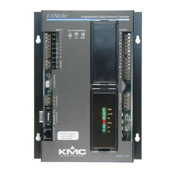
About the controllers KMD-5205 and KMD-5270 Installation and Operation Controls and connections Controls and Before installing a KMD-5205 or KMD-5270, take some time to become familiar with the location of the components of the controller. connections Pull-up jumpers STATUS H O A... -
Page 12: Safety Considerations
KMC Controls Safety considerations KMC Controls assumes the responsibility for providing you a safe product and safety guidelines during its use. Safety means protection to all individuals who install, operate, and service the equipment as well as protection of the equipment itself. -
Page 13: Installing The Controllers
Review this information carefully for proper installation. Mounting Mount the controller inside of a metal enclosure. KMC Controls recommends using a UL-approved Enclosed Energy Management Equipment Panel such as a KMC model HCO-1034, HCO-1035 or HCO-1036. Insert #6 hardware through the two mounting holes on each side of the controller to securely fasten it to a flat surface. -
Page 14: Connecting Outputs
An LED for assessment of the output state. Install the output override cards in the area under the plastic cover next to the output terminals. The following output cards are available from KMC Controls. Table 2-1 Output override cards Card model number... -
Page 15: Connecting To Networks
Ethernet configuration. Initializing with HCM KMC Tier 2 networks Connect KMC Tier 2 controllers to a KMD-5205 or KMD-5270 at the RS-485 connector. The KMC Tier 2 network uses shielded twisted pair cable to connect controllers together. See Initializing with HCM... - Page 16 Set the end-of-line termination to using the switches. The KMD-5205 and KMD-5270 end-of-line termination is set with two switches located near the RS–485 connector. Termination in other KMC controllers may be set with moveable jumpers or fixed resistors.
-
Page 17: Bacnet 8802-3 (Optional)
Installing the controllers KMD-5205 and KMD-5270 Installation and Operation BACnet 8802-3 (optional) Note Set the End-of-Line termination at the controllers where only one wire is attached to the A and B terminals. STATUS H O A STATUS H O A... -
Page 18: Modbus (Optional)
Modbus (optional) KMC Controls Modbus (optional) Connect Modus slave controllers to a KMD-5205 or KMD-5270 at the RS-485 connector. The Modbus network uses shielded twisted pair cable to connect controllers together. To set up the controller, see on page 27... - Page 19 Installing the controllers KMD-5205 and KMD-5270 Installation and Operation Modbus (optional) Modbus end-of-line termination switches The controllers on the physical ends of the Modus wiring segment must have end-of-line termination installed for proper network operation. For the KMD controllers the end-of-line termination is set with two switches located near the RS-485 connector.
-
Page 20: Connecting Power
The controllers require an external, 24 volt, AC power source. Use the following guidelines when choosing and wiring transformers. ◆ Use a KMC Controls Class–2 transformer of the appropriate size to supply power to the controllers. When installing a controller in a system with other controllers, you may ◆... -
Page 21: Connecting To A Computer Through The Serial Port
H O A KMD–5673 cable STATUS H O A STATUS H O A STATUS H O A STATUS H O A STATUS H O A STATUS H O A S-LAN COLL Illustration 2-7 Direct connection to KMD-5205 and KMD-5270 Revision J... -
Page 22: Connecting To A Modem
Detail KMC Controls recommends using U.S. Robotics modems for off-site communications. KMC does not offer support for other modem installations. To install a modem: 1. Use HCM to configure the controller for the modem function. See on page 27 for setup details. -
Page 23: Operating The Controller
KMD-5205 and KMD-5270 Installation and Operation SECTION 3 Operating the controller This section provides general operating parameters of your KMC controller and a detailed description of the front panel display. Lights and indicators Isolation bulbs Two small bulbs located next to the RS-485 connector are protective isolation bulbs for the Tier 2 networks. -
Page 24: Powering The Controller
Operating the controller Powering the controller KMC Controls LED indicators Six LEDs on the front of the controller display system status. Use the LEDs to confirm proper operation or as an aid when troubleshooting. PWR Flashes green during normal operation. The normal cycle is one second on and one second off. -
Page 25: Resetting The Controller
Operating the controller KMD-5205 and KMD-5270 Installation and Operation Resetting the controller Resetting the Use the reset button for either of the following functions. controller Restore the modem settings. ◆ ◆ Restore all configuration settings to the factory default settings. - Page 26 Operating the controller Resetting the controller KMC Controls Revision J...
-
Page 27: Configuration And Programming
SECTION 4 Configuration and programming This section lists initialization settings and describes programming functions that are unique to configuring the KMD-5205 and KMD-5270 controllers. Other programming features and more detailed instructions are covered in the WinControl XL User’s Plus Reference... - Page 28 Enter the address that is assigned to the controller on the KMD Tier 1 network. Valid entries are 1–31. Last Panel Not applicable on any KMD-5205 or KMD-5270 models. SubLAN A Sets the connection speed of the Tier 2 port to which the controller is connected.
- Page 29 3. Open an MS-DOS window on your computer and Ping the controller’s IP address. If the controller is operating correctly, you should receive a response to the ping command. If you are unfamiliar with the above steps, contact KMC Controls for assistance Revision J...
-
Page 30: Setting Up For Bacnet Networks
Not applicable to KMD-5205 or KMD–5270 models. Detail BACnet device settings are covered in more detail in BACstage or TotalControl help. The BACstage and TotalControl reference guides are available also in Adobe Acrobat format on the KMC Controls web site. Revision J... -
Page 31: Control Basic Programming For Bacnet
◆ other objects on other BACnet devices. KMC Controls recommends that all BACnet services have adequate error handling protocols within your control program. The following Control Basic code segment demonstrates reading the state of binary input BI8 in a BACnet device with instance number 1. -
Page 32: Setting Up For Modbus Networks
Data Set to even, odd or no parity bits Programming for Use WinControl XL Plus to map Modbus registers to variables in the KMD-5205 and KMD-5270 Modbus licensed controllers. Once the registers are mapped to Modbus in variables, the variables are handled with Control Basic to read from and write to WinControl XL Plus the registers. -
Page 33: Firewalls And Network Communications
Configuration and programming KMD-5205 and KMD-5270 Installation and Operation Firewalls and network communications Firewalls and Firewalls are commonly installed on networks to prevent unauthorized traffic or electronic probes from entering the network. If the controller must communicate network with a network where a firewall is in place, the following actions must be taken. -
Page 34: System Graphics
Configuration and programming System graphics KMC Controls System graphics These topics apply only to the following models: ◆ KMD-5270 ◆ KMD-5270-005 ◆ KMD-5270-001 ◆ KMD-5270-006 The KMD-5270 WebLite models can store up to eight system group background graphics which can then be served to a standard web browser. Use the following procedure in WinControl XL Plus to make a graphic available for browser access. -
Page 35: Using A Web Browser (Kmd-5270 Models Only)
KMD-5205 and KMD-5270 Installation and Operation SECTION 5 Using a web browser (KMD-5270 models only) This section explains how to view and control a KMD-5270 with a web browser. Through the embedded HTTP server in the KMD-5270, you can use a web browser to view and make changes to the following functions in the controller. -
Page 36: Browser Requirements
Using a web browser (KMD-5270 models only) Browser requirements KMC Controls Browser Use only Microsoft Internet Explorer to view the web pages in a KMD-5270 controller. The browser requires the Java Virtual Machine, a product of Oracle, to requirements view the trend graphs in the controller. Download the Java Virtual Machine at the following address. - Page 37 Using a web browser (KMD-5270 models only) KMD-5205 and KMD-5270 Installation and Operation Opening the WebLite home page Log in and security When the home page is open, click Login and then enter your user name and password. Only assigned operators can view or make changes to a WebLite controller.
-
Page 38: Viewing And Editing
Using a web browser (KMD-5270 models only) Viewing and editing KMC Controls Viewing and editing Controlling a system through a WebLite is limited to making changes to values, setting the state of manual overrides and changing times and dates in schedules. - Page 39 Using a web browser (KMD-5270 models only) KMD-5205 and KMD-5270 Installation and Operation Viewing and editing To make changes to values: 1. Click Edit. The Edit window opens. 2. Enter a new value. 3. Click and the change is sent to the controller.
-
Page 40: Pid Controllers
Using a web browser (KMD-5270 models only) PID controllers KMC Controls PID controllers PID controllers are managed the same as the input function described in Viewing and editing on page Illustration 5-6 PID control loop Trend Logs Trend logs may be viewed as either a table or graph. - Page 41 Using a web browser (KMD-5270 models only) KMD-5205 and KMD-5270 Installation and Operation Trend Logs 2. Click No Zoom to return to normal view. Illustration 5-7 Trend log graph Revision J...
-
Page 42: Schedules
Using a web browser (KMD-5270 models only) Schedules KMC Controls Schedules Weekly and annual schedules are managed much the same as with WinControl. The method for editing a weekly schedule is described in Viewing and editing page Illustration 5-8 Weekly and annual schedules...
Need help?
Do you have a question about the KMD-5205 and is the answer not in the manual?
Questions and answers