
Related Manuals for KMC Controls KMD-5210


Summary of Contents for KMC Controls KMD-5210
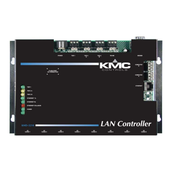
- Page 1 Installation and Operation Guide KMD-5210 LAN Controller KMD-5210–001 LAN Controller with BACnet 802.3 KMD-5210–002 LAN Controller with BACnet MS/TP Revision E 883-019-07E...
- Page 2 KMC Controls, Inc. makes no representations or warranties with respect to this manual. In no event shall KMC Controls, Inc. be liable for any damages, direct or incidental, arising out of or related to the use of this manual.
-
Page 3: Table Of Contents
KMD–5210 Installation and Operation Contents Section 1 About the LAN controller Introduction .......................... 5 BACnet options ........................5 Specifications ........................6 Options and Accessories ..................... 9 Controls and Connections ....................10 Safety Considerations ....................... 11 Section 2 Installation Mounting ..........................13 Network connections ...................... - Page 4 KMC Controls Revision E...
-
Page 5: About The Lan Controller
HVACR equipment. The KMD-5210 uses a token passing protocol in Tier 1 networks using an Ethernet network to communicate with other LAN Controllers. The LAN Controller also supports Tier 2 networks with two dedicated EIA–485 ports. -
Page 6: Specifications
12–22 AWG wire. Note: Use the Tier 1 connection only when replacing KMD–5110 MultiNet controllers and Ethernet is not available. Contact KMC Controls techncial support for networking details. Tier 2 A and B EIA–485 protocol at rates up to 38 kilobaud. - Page 7 About the LAN controller KMD–5210 Installation and Operation Specifications Programmable Features Control Basic Programs 128 user-definable program areas Networked Points In 512 from each Tier 2 network 127 from Tier 1 network Networked Points Out 64 to each Tier 2 network 64 out to a Tier 1 network 64 PID control loops PID Control Loops...
- Page 8 Software WinControl XL Plus 1.06 or later TotalControl 1.8.1 or later Controllers Compatible with Tier 1 controllers firmware build 2.01 or later Dimensions Illustration 1-1 KMD-5210 Components Table 1-1 KMD-5210 Dimensions Height (not shown) 10.50 in. 6.50 in. 0.25 in.
-
Page 9: Options And Accessories
About the LAN controller KMD–5210 Installation and Operation Options and Accessories Options and Accessories Modules KMD-5220 Input Module KMD-5221 Output Module Ribbon Cables for Input and Output Modules KMD-5660 6 inch (15 cm) ribbon cable KMD-5668 9 inch (23 cm) ribbon cable 14 inch (36 cm) ribbon cable KMD-5661 KMD-5662... -
Page 10: Controls And Connections
About the LAN controller Controls and Connections KMC Controls Controls and Connections Before installing the KMD-5210 LAN Controller, take some time to become familiar with the controller layout and components. Tier 1 Tier 2 BACnet Reset button Power EIA–485 EIA–485... -
Page 11: Safety Considerations
Safety Considerations Safety Considerations KMC controls assumes the responsibility for providing you with a safe product and safety guidelines for its proper use. Safety means protection to all individuals who install, operate and service the equipment as well as protection of the equipment itself. To promote safety, we use hazard alert labeling in this manual. - Page 12 About the LAN controller Safety Considerations KMC Controls Revision E...
-
Page 13: Installation
KMD-5210 LAN Controller. Carefully review this information prior to installation. Mounting Mount the controller inside of a metal enclosure. KMC Controls recommends using a UL-approved Enclosed Energy Management Equipment Panel such as a KMC model HCO–1034, HCO–1035 or HCO–1036. Insert #6 or #8 hardware through the two mounting holes on each side of the controller to securely fasten it to a flat surface. -
Page 14: Network Connections
An example of a typical installation is shown in Illustration 2-2. Each KMD-5210 in a KMC digital network may operate in either a stand-alone mode or connected by network to other controllers. The LAN Controller may be connect to other controllers using one or more of four network technologies. - Page 15 Installation KMD–5210 Installation and Operation Network connections Up to 32 LAN Controllers can be connected to the same Ethernet backbone in a common Ethernet network. This configuration also allows multiple PCs to access the system through the Ethernet network. Connect the controller to the network by connecting a standard 10BaseT Ethernet cable (CAT 5) to the Ethernet/BACnet port on the controller and to a port on the network hub or router.
-
Page 16: Eia-485 Networks
◆ Use the Tier 1 port (marked Main Net on older controllers) to connect several KMD-5210. This is an alternative to connecting LAN Controllers to each other with Ethernet. This port will allow up to 31 controllers to be connected together by network. - Page 17 Installation KMD–5210 Installation and Operation EIA–485 networks Refer to Illustration 2-4 for an example of typical EIA–485 connections. KMC controller connections Illustration 2-4 Typical EIA–484 Wiring Configuration End-of-line termination Each EIA–485 network segment requires end-of-line termination for proper operation of the network. Proper termination prevents signal degradation and EMI type interference with other system wiring.
-
Page 18: Bacnet Networks
Programming for BACnet in WinControl XL BACnet features. Note The BACnet options are licensed for each controller. To upgrade a KMD-5210 controller to BACnet, contact KMC Controls for license information. BACnet 802.3 The KMD-5210–001, the BACnet 802.3 version of the LAN controller, connects to the LAN in the same manner as the standard LAN controller. - Page 19 Installation KMD–5210 Installation and Operation BACnet networks BACnet MS/TP Connect a KMD-5210–002 controller to a BACnet MS/TP network at the connector . See on page 16 for network wiring EIA–485 EIA–485 networks techniques. To configure a KMD-5210–002 for network connections, see...
-
Page 20: Planning For Input And Output Modules
Planning for input and output modules To connect inputs or output devices to a KMD-5210 controller, use KMD-5220 input and KMD-5221 output modules. The KMD-5210 controller includes eight universal I/O ports for up to eight KMD-5220 input modules, eight KMD-5221 output modules or any combination of up to eight modules. -
Page 21: Module Installation
1. Position and mount the modules in the enclosure using the supplied mounting holes. 2. Connect the ribbon cable to the LAN Controller. Estimate the required cable length and select from one of the cables from KMC Controls. See on page 9 in the Options and Ribbon Cables for Input and Output Modules Accessories section. -
Page 22: Connecting Power
The controller does not use an power switch. See Applying power page 27 for additional information. Caution Use only a KMC Controls power supply. Powering the controller with an improper supply may result in damage to the controller. Revision E... -
Page 23: Connecting To A Computer
Computer B port is disabled and is not available for direct connection with a computer. Note KMC Controls recommends using U.S. Robotics modems for off-site communications. KMC does not offer support for other modem installations. KMD–5569 modem Standard 9–pin to... - Page 24 Down 4. Use HCM to initialize Computer Port B for modem operation. Connecting a KMD-5210 to an Ethernet LAN To connect a PC to the controller via the Ethernet, the PC a must have a valid IP address on the Ethernet network that connects to the controller and install the PC on the Ethernet.
- Page 25 Installation KMD–5210 Installation and Operation Connecting to a Computer Note EIA–232 port B is assigned the same address as the modem port. When the modem port is in use, a PC cannot be connected to the controller through serial port B.
- Page 26 Installation Connecting to a Computer KMC Controls Revision E...
-
Page 27: Operation
Carefully review this information as it applies to the task at hand. Applying power The KMD-5210 LAN Controller is automatically powered when the power supply module is connected and plugged in. Verify all external connections are complete before applying power to the controller. - Page 28 KMC Flash Wizard. Erratic or Repeating Pattern Blink – If the LED is blinking, but not at a steady rate, the controller is indicating there is a problem with the license. Contact KMC Controls for assistance. Revision E...
-
Page 29: Resetting The Controller
Operation KMD–5210 Installation and Operation Resetting the controller Resetting the controller Should the controller appear to lock up or stop operating, you must reset the controller to the factory default state. After the controller is reset, you must reload any existing panel files to restore normal operation. (See the section on page 32 for additional details Configuring a controller with HCM... - Page 30 Operation Resetting the controller KMC Controls Revision E...
-
Page 31: Configuration And Programming
Programming Considerations The design of the KMD-5210 LAN Controller provides areas where specific user programs may be stored. This allows a great deal of versatility and function in the way the controller is used. It also allows for changes to the system to meet changing requirements or conditions. -
Page 32: Configuring A Controller With Hcm
Configuration and programming Configuring a controller with HCM KMC Controls Configuring a controller with Before placing a controller into service, it must be initialized and addressed with the KMC (HCM) software. HCM is Hardware Configuration Manager distributed with application programs; complete instructions for HCM are... - Page 33 Configuring a controller with HCM KMC digital network configuration The entries in the table HCM Configuration Screen setup fields on page 33 required for controller-to-controller communications on a KMC controls digital network. Table 4-1 HCM Configuration Screen setup fields Setting...
- Page 34 3. Open an MS-DOS window on your computer and Ping the controller’s IP address. If the controller is operating correctly, you should receive a response to the ping command. If you are unfamiliar with the above steps, contact KMC Controls for assistance. Revision E...
- Page 35 Detail BACnet device settings are covered in more detail in the BACstage Reference Guide that is available in Adobe Acrobat format on the KMC Controls web site. See the topic Device Objects in the section The Object Menu. Revision E...
-
Page 36: Programming For Bacnet In Wincontrol Xl
Use BAC-SET, BAC-GET and BAC-RLQ in Control Basic to read and write other objects on other BACnet devices. KMC Controls recommends that all BACnet services have adequate error handling protocols within your control program. A sample Control Basic code segment is provided below to demonstrate reading the state of Binary Input 8 in a BACnet device with instance number 1. -
Page 37: Access To The Lan Controller From Bacnet
The LAN Controller will appear in the BACstage device list but cannot ◆ be selected. Its objects are not accessible for configuration from the BACstage Object menu. The configured points within the KMD-5210 are the only points visible in ◆ BACnet. ◆... - Page 38 Configuration and programming System time keeping KMC Controls Revision E...
Need help?
Do you have a question about the KMD-5210 and is the answer not in the manual?
Questions and answers