Woodland Mills HM122 Owner's Manual
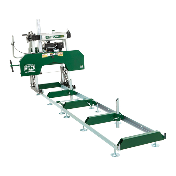
Portable sawmill
Hide thumbs
Also See for HM122:
- Operator's manual (108 pages) ,
- Assembly instructions manual (20 pages) ,
- Operator's manual (80 pages)
Table of Contents
Advertisement
Advertisement
Table of Contents

Related Manuals for Woodland Mills HM122


Summary of Contents for Woodland Mills HM122
- Page 1 HM122 PORTABLE SAWMILL 2017 HM122 OWNER’S MANUAL...
-
Page 2: Table Of Contents
TABLE OF CONTENTS GENERAL SAFETY RULES ………………………………………………..…….……. 3 GENERAL MAINTENANCE INFORMATION ………………..……………..….…….. 8 SAWMILL ASSEMBLY INSTRUCTIONS …………………………..………..….……. 9 SAWMILL SET-UP PROCEDURES ……………………………..………………..…… 28 BELT TENSION …………………………………………………..…..……..……..… 28 BLADE TRACKING ………………………………………………..………………… 30 BLADE GUIDE ADJUSTMENT ……………………………..……………………… 36 NYLON BOLT ADJUSTMENT ……………………………………………………… 36 SAWMILL MAINTENANCE ………………………………..……………………………... - Page 3 INTRODUCTION Congratulations on your purchase and welcome to Woodland Mills. This manual gives you the necessary information about your machine so you will be able to use it properly. The entire manual must be read and understood before you start using the machine. If any questions should arise that are not covered by this manual, please contact Woodland Mills Inc.
-
Page 4: General Safety Rules
INTENDED USE This sawmill is designed for sawing logs while the mill is firmly supported on the ground. TECHNICAL SPECIFICATIONS ITEM DESCRIPTION Gasoline Engine 7.0 HP Kohler Maximum Log Diameter 22 ” (559mm) Maximum Board Width 18 ” (457mm) Maximum Board Thickness 6 ”... -
Page 5: Work Area
SAVE THESE INSTRUCTIONS WORK AREA • Keep work area clean, free of clutter and well lit. Cluttered and dark work areas can cause accidents. • Do not use your sawmill where there is a risk of causing a fire or an explosion; e.g. in the presence of flammable liquids, gasses, or dust. -
Page 6: Personal Safety
PERSONAL SAFETY • Stay alert, watch what you are doing and use common sense when operating a power tool. Do not use a power tool while you are tired or under the influence of drugs, alcohol or medication. A moment of inattention while operating power tools may result in serious personal injury. •... -
Page 7: Tool Use And Care
TOOL USE AND CARE • Always be sure operator is familiar with proper safety precautions and operation techniques before using the machine. • Never touch the engine or muffler while the engine is on or immediately after it has been turned off. - Page 8 EQUIPMENT OPERATION Wear heavy-duty work gloves, ANSI-approved goggles behind a full face shield, steel-toed work boots, and a dust mask. Operate only with assistance. Fill the lubrication tank with clean water and liquid soap. Start and operate the engine according to the provided engine manual. Depress the throttle to bring the blade up to speed.
- Page 9 MAINTENANCE Proper and routine maintenance is critical to operator safety, achieving good milling results and to prolonging the life of your investment. • Band Wheel Bearings — Inspect before use to ensure they are not worn. Bearings are sealed and do not need to be greased. •...
- Page 10 SAWMILL ASSEMBLY 1. UNPACKING Unpack the contents of the crate except for the sawmill head and the two long boxes in the bottom that contain the two sections of track. Unbolt the front of the crate and lay 6” (150mm) high support blocks in front of the crate.
- Page 11 2. TRACKS Assemble the track system with the provided nuts & bolts. It is important to assemble and level the track on a firm foundation before tightening all of the nuts and bolts. It is ideal to assemble the tracks on a solid and level footing that is a minimum of 4”...
- Page 12 The pictures below show the assembly of the log bunks to the “L” rails. Ensure that the two end bunks are square (90 degrees) to the track ‘L’ rails. 90 degrees Assemble carriage stops at the ends of the tracks (4 stops total) and tighten bolts as shown below. Page...
- Page 13 3. LOG DOG & SUPPORTS Assemble log dog pieces using the pieces shown below. Attach log dog assembly to track as shown below with the 2 M8x20mm bolts and nuts provided. Note that there are various locations along the track where this assembly can be bolted. Depending on how many track sections are being used, select a log clamp position that will secure the log firmly against the log supports.
- Page 14 Insert log supports into track cross supports and secure with “T” handles as shown in the picture below. The “T” handle threads should be coated with grease. The sawmill includes two sets of log supports – a short set and a long set. The longer set is ideal for larger logs and the shorter set is ideal for small logs and square cants.
- Page 15 4. SAWMILL HEAD ASSEMBLY The below chart shows the various bolts that will be used to assemble the head of the sawmill. This chart may be used to ensure the correct bolts are used. M12 x 70 M12 x 80 Page...
- Page 16 With the saw head resting about 6” (150mm) above the ground. Slide the 2 front posts into the slots as shown below. Using 4 of the M12 x 80mm bolts, washers and lock nuts, attach the saw head carriage plate assembly to the bottom of the posts.
- Page 17 With the help of another person, stand the saw head to its upright position. Attach the back handle between the plates using 2 of the M12 x 80mm bolts per side. Do not fully tighten these bolts at this time. ...
- Page 18 Using 4 of the M12 x 70 bolts, with the help of another person, attach the top cross support to the posts. Make sure the spacer is in the correct position. Do not fully tighten these bolts at this time. ...
- Page 19 Attach and route the cables as shown below. Be sure to tighten the oval chain link with a wrench after the cable loop end has been attached. Page...
- Page 20 Attach the lubrication tank bracket and heat shield using M8 x 20 bolts. Install the lubrication tank into the bracket. Insert the lubrication tube into the fitting on the tank by pushing the blue collar in at the same time the tube is inserted.
- Page 21 Attach the other lubrication tube from the valve and feed it through the hole in the back bar and through the water tube bracket and fit it over the end of the copper tube. Attach the metal scale bracket to the sawmill head using the two nuts and bolts provided. Use a 10mm socket to tighten.
- Page 22 Install the round bar and the throttle handle to the round bar as shown in the image below. With the throttle lever in the idle position/fully open, pull the cable tight at the engine and tighten the screw to hold it in place.
- Page 23 5. PLACING THE HEAD ON THE TRACK Before placing the head on the track, the carriage wheel spacing can be set to ensure they will fit properly on the “L” rails. Check the wheel spacing to ensure that a distance of 26” (660mm) is measured from outside to outside of the wheel grooves as shown below.
- Page 24 At this point, most of the sawmill head bolts should only be hand tight. They will be fully tightened when the head is on the track and has settled in a true and square state. Two people are needed for this. Start by removing the “L” shaped brackets on the end of the tracks. The head can be walked over to the track until it is positioned behind the track as shown below.
- Page 25 Using a tape measure, take a measurement from the blade to the top of the log bunk on both the left and right side. The distance should be equal on both sides. If it isn’t, you will need to adjust the cable ends on the right side to either raise or lower the right side.
- Page 26 Add waterproof grease to the threads of the blade tension “T” handle and to the washer face that it meets before use. Proper blade tension is achieved when a 24mm socket is used on a torque wrench to tighten the “T” handle to 25 ft-lbs (34 N-m) torque. See the images below. *Note –...
- Page 27 Install the 3 latches on the band wheel housing doors, if they are not already installed. Only the 2 bottom latches require a spacer. Spacer Latch Push the saw head up and down the track system to ensure that the width of the track allows for the saw head to move freely.
- Page 28 6. ENGINE Refer to the engine manual before using your sawmill. Please note that the engine does not contain any gasoline or engine oil when it is shipped. Furthermore, the engine is equipped with an oil alert system, meaning that if the crankcase oil level is low or empty, the power is cut to the spark plug and it will not start.
-
Page 29: Sawmill Set-Up Procedures
SAWMILL SET-UP PROCEDURES 1. BELT TENSION Follower Belt – This is a polyurethane belt and will be seated tightly in the band wheel vee groove. No adjustment is required for this belt. Drive Belt - To check the belt tension, with your hand, firmly try to deflect the belt up and down. There should be no more than 1/4”... - Page 30 Now that the engine is free to slide on the engine mounting plate, turn the nut on the horizontal stud in the clockwise direction. This will pull the engine towards the stud and apply more tension on the belt. Do this step incrementally while checking the belt for proper deflection. It is also important to ensure that the engine remains perpendicular to the drive belt.
-
Page 31: Blade Tracking
2. BLADE TRACKING Never attempt to adjust the blade tracking with the engine running. As a safety precaution, remove the spark plug cap. It is also advised to wear gloves and safety glasses when working with the blade as it is extremely sharp. Left Side of Sawmill Right Side of Sawmill The blade should run with the same tooth to band wheel face distance on both sides. - Page 32 Loosen the blade guide assembly bolt with a 16mm socket. The round shaft should now be free to slide rearward and out of the way. Perform this step on both guide assemblies. This will ensure that the guide bearings do not influence tracking of the blade while adjusting. Take some tension off of the blade by turning the “T”...
- Page 33 Adjusting The Right Hand Side Loosen the tracking alignment locking nut with a 24mm wrench or an adjustable wrench. The alignment bolt can now be turned to change the angle of the band wheel and track the blade. To move the blade more rearward on the band wheel, this bolt will need to be turned clockwise. Alternatively, turning the bolt in the counter-clockwise direction would force the blade to run more forward on the band wheel.
- Page 34 Wearing gloves, spin the band wheel with your hand and observe how the blade has changed tracking. Measure the distance again and repeat the above step to further compensate if required. The ideal measurement is 3/8" (9mm) or check for the back of the blade to be flush with the back of the band wheel.
- Page 35 Adjusting The Left Hand Side To adjust the left side of the sawmill, again start by taking the tension off of the blade by turning the “T” handle one turn in the counter-clockwise direction. Using an 18mm wrench, loosen the “vertical nut”...
- Page 36 Re-tension the blade by turning the “T” handle a full turn in the clockwise direction (to achieve 25 ft- lbs (34 N-m)). Wearing gloves, spin the band wheel with your hand and observe how the blade has changed tracking. Measure the distance again and repeat the above step to further compensate if required.
-
Page 37: Blade Guide Adjustment
3. BLADE GUIDE ADJUSTMENT Never attempt to adjust the guide blocks or the guide bearing with the engine running. As a safety precaution, remove the spark plug cap. It is also advised to confirm that the blade is tracking properly before performing the below. Blade tracking is covered in the previous page. Using a 4mm allen key, loosen the blade guide blocks on both the left and right sides. -
Page 38: Nylon Bolt Adjustment
Using a thick piece of paper (0.020” or 0.5mm) in between the blade and both blade guide blocks, tighten the set screws. 0.020” (0.5mm) gap 0.040” (1mm) gap 4. NYLON BOLT ADJUSTMENT Tighten the 4 nylon bolts so the head is snug on the posts, but still free to slide up and down. There are 2 bolts on each side of the mill, one on top and one on the bottom. -
Page 39: Sawmill Maintenance
SAWMILL MAINTENANCE 1. BLADE TENSION Proper blade tension is achieved when a 24mm socket is used on a torque wrench to tighten the “T” handle to 25 ft-lbs (34 N-m) torque. Make sure the spring washers are installed like the picture below. -
Page 40: Replacing Belts
3. REPLACING BELTS Never attempt to replace the belts with the engine running. As a safety precaution, remove the spark plug cap. Gloves and safety glasses must be worn when replacing the belts. There are two vee belts on the sawmill. It is recommended to to use a BX63 cogged belt for the drive side and a Woodland Mills polyurethane follower belt. - Page 41 To change the drive side belt, loosen the four bolts that secure the engine to the engine mount using wrenches. Now that the engine is free to slide on the engine mounting plate, turn the 17mm nut on the horizontal stud in the counter-clockwise direction. This will allow the engine to move and will also take the tension off of the belt.
-
Page 42: Troubleshooting
TROUBLESHOOTING Problem / Issue Possible Causes Resolution Options Producing wavy cuts. 1. Inadequate blade tension. 1. Tighten blade. Refer to page 38. 2. Improper blade guide set up. 2. Gap between guide blocks and blade are incorrect. 3. Improper blade tracking. Refer to page 36. ... -
Page 43: Parts List
PARTS LIST HM122 - Parts List Part No. Description Specification Quantity Part No. Description Specification Quantity Lock Nut Spacer Plate Lock Nut Spacer Hex Bolt M20 x 110 Circlip Ø42 Hex Bolt M12 x 80 Throttle Cable Hex Bolt M8 x 20... - Page 44 PARTS LIST HM122 - Parts List Part No. Description Specification Quantity Part No. Description Specification Quantity Socket Head Cap Screw M10 x 30 Cogged Belt BX64 Heat Shield Polyutherane Belt Hex Bolt M12 x 30 Band Wheel Door (Left) Hex Bolt...
-
Page 45: Part Diagrams
DIAGRAM Page... - Page 46 DIAGRAM Page...
- Page 47 DIAGRAM Page...
- Page 48 DIAGRAM Page...
- Page 49 DIAGRAM Page...
-
Page 50: Notes
NOTES Page...
Need help?
Do you have a question about the HM122 and is the answer not in the manual?
Questions and answers