
Related Manuals for RINCO ULTRASONICS AG Standard 3000

Summary of Contents for RINCO ULTRASONICS AG Standard 3000
-
Page 1: Fig. 6 Controls And Indicators Welding Press
RINCO ULTRASONICS AG Operating instructions Read the operating instructions before carrying out any work Standard 3000 with ADG generator Translation of the original operating instructions (English) -
Page 2: Fig. 7 Controls And Indicators Welding Press
These operating instructions are protected by RINCO ULTRASONICS AG copyright and intended solely for internal purposes. Industriestrasse 4 Transfer of the operating instructions to third CH-8590 Romanshorn parties, reproduction of any kind - also in part - as Switzerland well as the use and/or disclosure of the contents Tel. -
Page 3: Table Of Contents
RINCO ULTRASONICS AG Contents Contents 1 General information Information on these operating instructions Explanation of symbols Disclaimer Warranty terms Customer service and product monitoring 2 Safety requirements Introduction Responsibility of the operator Personnel requirements 2.3.1 General personnel requirements 2.3.2 Qualifications 2.3.3... -
Page 4: Fig. 38 Jumpers
Contents RINCO ULTRASONICS AG 3.6.2 Programming an initial application 3.6.3 Welding modes 4 Transport, packaging and storage Safety warnings for transport Delivery (packaging/packages) Transporting packages by forklift truck or lifting cart Transporting the sound enclosure by forklift truck or lifting cart... -
Page 5: Tab. 33 Sound Enclosure Errors
RINCO ULTRASONICS AG Contents 6.5.1 Installing the oscillator system 6.5.2 Replacing the booster 6.5.3 Setting up the tool 6.5.4 Aligning the fixing plate Steps prior to use Starting the machine Switching off 7 Maintenance Safety instructions Maintenance schedule 7.2.1 Daily maintenance work on work finish 7.2.2... - Page 6 Contents RINCO ULTRASONICS AG 9.1.2 Personal protective equipment 9.1.3 Safety instructions Measures before disassembly Disassembly Disposal 10 Technical data 10.1 General information 10.2 Dimensions and weights 10.3 Connected loads, limit values, electrical 10.4 Connected loads, pneumatic 10.5 Press 10.6 Base 10.7...
-
Page 7: General Information
These instructions describe the ultrasonic welding systems Standard 3000 Legal force and Standard 3000 with sound enclosure SSK-H or SSK-K in operation with the generators ADG 20-1000, ADG 20-1500, ADG 20-2000 and ADG 20-3000. The purpose of this manual is to provide the customer and operator with all... -
Page 8: Explanation Of Symbols
1 | General information RINCO ULTRASONICS AG Explanation of symbols Symbols are used to denote safety warnings in these instructions. Signal Safety instructions words are found at the start of the safety warnings are used to express the severity of the hazard. -
Page 9: Disclaimer
RINCO ULTRASONICS AG General information | 1 Disclaimer The information and safety instructions in these operating instructions have Information in these instructions been composed with regard to the applicable standards, guidelines and regulations, the state of technology and our years of experience. -
Page 10: Warranty Terms
1 | General information RINCO ULTRASONICS AG Terms of warranty With the delivery of the machine, RINCO ULTRASONICS AG has assumed Location a warranty obligation according to VSM (Swiss Machine Manufacturer Association). The following requirements must be met for RINCO ULTRASONICS AG to fulfill its warranty obligations: ▪ The user must have knowledge of the content of these operating instruc-... -
Page 11: Customer Service And Product Monitoring
In the case of technical malfunctions and welding problems, the Technical Customer Service Customer Service of RINCO ULTRASONICS AG will be happy to help. See the Legal Notice for contact details. For requests concerning your ultrasonic welding machine Standard 3000... -
Page 12: Safety Requirements
2 | Safety requirements RINCO ULTRASONICS AG Safety requirements Introduction This section provides an overview of all key safety aspects for optimum safety of the personnel, as well as safe and trouble-free operation. Non-compliance with the instructions and safety warnings in these operating instructions can result in considerable risks. -
Page 13: Personnel Requirements
RINCO ULTRASONICS AG Safety requirements | 2 Personnel requirements 2.3.1 General personnel requirements Authorised personnel are those who carry out their task reliably and whose responses are not impaired by e.g. drugs, alcohol or medication. When selecting personnel, observe the applicable job-specific age regulati- ons applicable at the location of operation of the machine. -
Page 14: Unauthorised Persons
2 | Safety requirements RINCO ULTRASONICS AG 2.3.3 Unauthorised persons WARNING Unauthorised persons without knowledge of the dangers in the working area. Danger of severe injury! • Unauthorised persons must be kept away from the working area. • In case of doubt, talk to the persons and instruct them to leave the working area. -
Page 15: Personal Protective Equipment
RINCO ULTRASONICS AG Safety requirements | 2 Personal protective equipment Some tasks require personal protective equipment to be worn. To minimise dangers to health, the mandatory personal protective equipment suitable for the work must be worn. In addition to the personal protective equipment specified in these operating instructions, also observe the attached warnings in the working area. -
Page 16: Residual Risks
2 | Safety requirements RINCO ULTRASONICS AG Residual risks The following section of these operating instructions indicates residual risks that were identified in a risk assessment. It is essential that you read these safety instructions and information in the following chapters and take measures to avert dangers, reduce health hazards and avoid dangerous situations. -
Page 17: Mechanical Hazards
RINCO ULTRASONICS AG Safety requirements | 2 2.5.2 Mechanical hazards WARNING Rotating and/or linearly moving components. Danger of severe injury! • Do not reach into or touch moving components during operation. • Do not open covers during operation. • Observe the shut-down period: Before opening the covers, make sure that no components are still moving. -
Page 18: Hazards At The Operating Site
2 | Safety requirements RINCO ULTRASONICS AG 2.5.3 Hazards at the operating site Insufficient lighting WARNING Insufficient lighting. Safety hazards due to incorrect execution of work. Danger of severe injury! • Provide sufficient lighting at the workplace. (The operator must provide sufficient lighting at the machine's location according to regional occupational safety regulations. -
Page 19: Emergency Shutdown
RINCO ULTRASONICS AG Safety requirements | 2 Emergency shutdown The machine must be shutdown immediately in the event of imminent danger to the user or damage to the press. – Press the EMERGENCY STOP button (1). ð The press returns to the start position. -
Page 20: Symbols/Pictograms
2 | Safety requirements RINCO ULTRASONICS AG Symbols/pictograms Illegible symbols/pictograms WARNING Inability to recognise hazards due to illegible or missing symbols/pictograms. Danger of severe injury! • Make sure that all safety instructions, warnings and opera- ting instructions are always clearly legible. -
Page 21: Intended Use
RINCO ULTRASONICS AG Safety requirements | 2 Intended use The machine is designed and engineered exclusively for the applications described in this document and must only be used for those purposes. ▪ The ultrasonic welding machine Standard 3000 and its accessories are Intended use intended solely for the welding and cutting of suitable materials. Inform yourself about potential dangers involved in ultrasonic welding and cutting. - Page 22 2 | Safety requirements RINCO ULTRASONICS AG Intended use also includes compliance with all information contained in these instructions. All other or contradictory use of the machine is considered misuse and can result in dangerous situations. Unintended use WARNING Unintended use Danger of severe injury! •...
-
Page 23: Machine Description
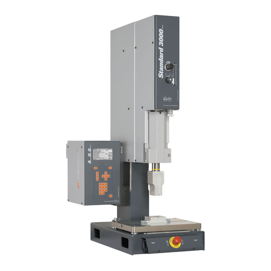
RINCO ULTRASONICS AG Machine description | 3 Machine description Overview/assemblies 3.1.1 Complete system Overview Fig. 3: Complete system Item no. Description Press Generator/control Fixing plate Actuation unit with EMERGENCY STOP button Converter housing with oscillator unit Tab. 1: Press design BA_Standard3000_GB_V5.1_36566... -
Page 24: Sound Enclosure (Optional)
3 | Machine description RINCO ULTRASONICS AG 3.1.2 Sound enclosure (optional) Overview Fig. 4: Sound enclosure Item no. Description Sound enclosure Generator ADG and generator mount Control cabinet with main switch Actuation unit with EMERGENCY STOP button Lift-up doors Installation doors Tab. -
Page 25: Oscillator Unit
RINCO ULTRASONICS AG Machine description | 3 3.1.3 Oscillator unit 3.1.3.1 Overview Example Converter: 5 µm Booster: 10 µm Horn: 30 µm Converter = 5 µm Booster = 1:2 10 µm Horn = 1:3 30 µm Fig. 5: Oscillator unit Item no. -
Page 26: Tab. 3 Reducer Booster
3.1.3.4 Sonotrode The sonotrodes must be configured for 20 kHz and can be optimised for vari- ous application areas. RINCO ULTRASONICS AG will be pleased to assist you in choosing the right type. 26 / 137 BA_Standard3000_GB_V5.1_36566... -
Page 27: Controls And Indicators
RINCO ULTRASONICS AG Machine description | 3 Controls and indicators 3.2.1 Welding press Fig. 6: Controls and indicators of welding press 1/2 Item no. Description Converter housing Sonotrode Fixing plate Two-hand release button Parallel adjustment nuts Tab. 5: Welding press part 1 BA_Standard3000_GB_V5.1_36566... -
Page 28: Tab. 6: Welding Press Part 2
3 | Machine description RINCO ULTRASONICS AG Fig. 7: Controls and indicators of welding press 2/2 Item no. Description Fine adjustment screw for depth stop (Nonius) EMERGENCY STOP button Scale for actuator / depth gauge (0 to 100 mm) Trigger mark... - Page 29 RINCO ULTRASONICS AG Machine description | 3 3.2.1.1 Converter housing The oscillator system with the electrical leads is located in the converter housing (1). 3.2.1.2 Sonotrode The sonotrode (2) is the actual welding tool. The manufacturer configures it according to the resonance frequency.
-
Page 30: Fig. 8 Pressure Regulator Dr
3 | Machine description RINCO ULTRASONICS AG 3.2.1.8 Scale for actuator / trigger mark The scale (8) is used to measure or adjust the actuator. The safety switch is activated if the trigger mark (8.1) is crossed. The cycle then continues automatically without actuation of the two-hand release (6 mm). -
Page 31: Fig. 9 Throttle Vd Diagram
RINCO ULTRASONICS AG Machine description | 3 3.2.1.15 Throttle VD The throttle (15) has two functions: ▪ Speed reduction for the last 30 mm of travel. ▪ Temporal force build-up after sonotrode has set down on plastic part. See illustrations in the quick guide under the machine table top. Practical setting: 7 The two functions mentioned above must be understood in combination with the trigger force, the so-called trigger. -
Page 32: Generator/Aui Control Module
3 | Machine description RINCO ULTRASONICS AG 3.2.2 Generator/AUI control module The program dialogue and the process results are shown on the display. After start-up, the process data can no longer be changed. Data can be easily retrieved. Overview of generator Fig. -
Page 33: Fig. 12 Pin Codes
RINCO ULTRASONICS AG Machine description | 3 3.2.2.1 Function keys F1 and F2 The function keys correspond to the bar displayed at the bottom of the screen and are used to navigate through the menu levels. 3.2.2.2 Skip buttons Ultrasonic oscillator test during idling. - Page 34 3 | Machine description RINCO ULTRASONICS AG 3.2.2.5 Status bar The status bar provides information on the last completed step of the gene- rator. The parameterised welding mode is displayed to confirm whether the next welding cycle can be performed. Information is provided on the fol- lowing states: ▪ Cycle active...
-
Page 35: Menu Tree
RINCO ULTRASONICS AG Machine description | 3 Menu tree START SCREEN RINCO SW version Button SYSTEM TEST SYSTEMTEST Project name Data set number AUI software version Generator DGC software version Press Power loss Frequency PIN 1000 Operator Button WELDING MAIN MENU... -
Page 36: Fig. 14: Menu Tree 2/3
3 | Machine description RINCO ULTRASONICS AG Part 1 TIME WINDOW Time limit SETUP Minimum Maximum Project name Time warning Data set number Minimum System pressure Maximum Recommendation throttle Travel Trigger ENERGY WINDOW Energy limit WELDING PARAMETER Minimum POWER WINDOW... -
Page 37: Fig. 4 Sound Enclosure
RINCO ULTRASONICS AG Machine description | 3 Part 2, Part 1 PARAMETER DATABASE DATABASE Parameter database Active data set Welding history Data set numbers 1-32 go to / store / load / delete / RS232 WELDING HISTORY Display of WELDING... -
Page 38: Connections
3 | Machine description RINCO ULTRASONICS AG Connections 3.4.1 Electrical connection The electrical connection is on the generator. The actual connected loads can be found in chapter Connected loads, limit values, electrical} 121]. Pin assignment see chapter Pin assignment 127]. -
Page 39: Compressed Air Connection
RINCO ULTRASONICS AG Machine description | 3 3.4.2 Compressed air connection The compressed air connection is located on the side of the welding press. The actual connected loads can be found in chapter Connected loads, pneumatic 121]. Fig. 17: Compressed air connection BA_Standard3000_GB_V5.1_36566... -
Page 40: Marking Locations
3 | Machine description RINCO ULTRASONICS AG Marking locations The type plates (A) and (B) clearly identify the machine. Fig. 18: Type plates The type plates are located on the side of the press (A) and on the rear of the generator (B). -
Page 41: Welding Technology
RINCO ULTRASONICS AG Machine description | 3 Welding technology The following parameters must be used to ensure a high-quality ultrasonic welding process within tight tolerances: ▪ Amplitude A [μm] as energy source and ▪ Contact force F [N] as the interface between the plastic parts to be welded. -
Page 42: Process
3 | Machine description RINCO ULTRASONICS AG 3.6.1 Process A welding cycle can be divided into six sequences: Zeit Fig. 22: Welding cycle sequences The individual process steps Rapid advance of the welding tool. 0–1 Forward stroke Reduction of lowering speed according to the throttle setting for smooth 1–2 Braking... -
Page 43: Programming An Initial Application
RINCO ULTRASONICS AG Machine description | 3 3.6.2 Programming an initial application When the press height is set, enter the boosters and the sonotrode you want Preparation to use under Information / Oscillator system information. The control can then calculate the correct value in [μm]. Set the system pressure so that an optimal welding result is achieved. -
Page 44: Welding Modes
3 | Machine description RINCO ULTRASONICS AG 3.6.3 Welding modes Under System Parameters / Option 1, the ultrasonic trigger (trigger) can be set as pressure (force), travel, time or external for all welding modes. For most applications, Force is the appropriate trigger option, in some cases travel can be selected. -
Page 45: Fig. 28 Energy Mode
RINCO ULTRASONICS AG Machine description | 3 3.6.3.4 ENERGY MODE 3.6.3.4 ENERGY MODE In Energy mode, the momentary power absorbed by the welding object is In Energy mode, the momentary power absorbed by the welding object is added up in small time intervals. To detect uniform welding quality, the added up in small time intervals. -
Page 46: Transport, Packaging And Storage
4 | Transport, packaging and storage RINCO ULTRASONICS AG Transport, packaging and storage Safety warnings for transport The press and generator must always be transported separately. Transport Always observe the transport instructions on the packaging. ▪ The transport must be carried out by specially trained skilled personnel Personnel only. The following personal protective equipment must be worn for all transport... - Page 47 RINCO ULTRASONICS AG Transport, packaging and storage | 4 Incorrect transport NOTICE Incorrect transport. Danger of considerable damage! • When unloading packages after delivery or transporting within the company, proceed with caution and observe the symbols and warnings on the packaging.
-
Page 48: Delivery (Packaging/Packages)
4 | Transport, packaging and storage RINCO ULTRASONICS AG Delivery (packaging/packages) The packaging serves to protect the machine until the time of assembly and Packaging should protect it against transportation damage, corrosion and other dama- ge. For this reason, do not dispose of the packaging and only remove it immediately before assembly. -
Page 49: Transporting Packages By Forklift Truck Or Lifting Cart
RINCO ULTRASONICS AG Transport, packaging and storage | 4 Transporting the packages by forklift truck or lifting cart The machine and the packages can be transported by forklift truck or lifting Conditions for transport cart in compliance with the following conditions: The forklift truck or lifting cart must be designed for the weight of the machi- ne and the package. -
Page 50: Transporting The Sound Enclosure By Forklift Truck Or Lifting Cart
4 | Transport, packaging and storage RINCO ULTRASONICS AG Transporting the sound enclosure by forklift truck or lifting cart The sound enclosure can be transported by forklift truck or lifting cart in Conditions for transport compliance with the following conditions: The forklift truck or lifting cart must be designed for the weight of the machi- ne and the package. -
Page 51: Transporting By Crane
RINCO ULTRASONICS AG Transport, packaging and storage | 4 Transporting by crane The press and sound enclosure can be transported by crane in compliance Conditions for transport with the following conditions: ▪ The sling gear must be designed for the weight of the press and sound enclosure. ▪ The operator of the crane must be authorised to do so. Lift the press as follows: Lifting the press –... -
Page 52: Fig. 31 Lifting The Sound Enclosure
4 | Transport, packaging and storage RINCO ULTRASONICS AG Lift the sound enclosure as follows: Lifting the sound enclosure – Attach the sling gear (ropes, belts, etc.) to the ring bolts. – Do not attach the sling gear too flat. -
Page 53: Transport Inspection
RINCO ULTRASONICS AG Transport, packaging and storage | 4 Transport inspection After receipt of the shipment, check whether all parts correspond to the package content list and that there is no visible damage. In the event of visible transport damage, proceed as follows: Do not accept the delivery, or accept it only with reservation. -
Page 54: Storage And Extended Downtimes
4 | Transport, packaging and storage RINCO ULTRASONICS AG Storage and extended downtimes Store packages and machine components under the following conditions: Storage of packages and machine components ▪ Do not store outside. ▪ Keep dry and dust-free. ▪ Do not expose to aggressive media. ▪ Protect against direct sunlight. ▪ Avoid mechanical vibration. ▪ Avoid extreme temperature fluctuations to prevent condensed water from forming. -
Page 55: Pictograms On The Packages
RINCO ULTRASONICS AG Transport, packaging and storage | 4 Pictograms on the packages The following pictograms may be found on the packages. They contain important information for safe transport. Observe existing pictograms. The arrows indicate the top side of the package. They must always be pointing upwards, otherwise the content may be damaged. -
Page 56: Assembly And Initial Start-Up
Do not touch electrical components or contacts. The ultrasonic welding machine Standard 3000 and the ADG generators are equipped with sensitive electrostatic components that can be easily damaged if not handled correctly. - Page 57 RINCO ULTRASONICS AG Assembly and initial start-up | 5 Incorrect installation and initial WARNING start-up Incorrect installation and initial start-up. Danger of severe injury! Danger of considerable damage! • Before starting work, make sure that there is sufficient space for assembly.
-
Page 58: Set-Up Location Requirements
The ultrasonic welding machine Standard 3000 and the ADG generator are General environmental conditions designed for ordinarily clean industrial environments. In order to install the machine and for the entire service life of the machine, make sure that: ▪ the Standard 3000 ultrasonic welding machine is not installed at locations... -
Page 59: Fig. 32 View Of Workplace
RINCO ULTRASONICS AG Assembly and initial start-up | 5 To ensure safe operation and when carrying out maintenance and start-up Space requirement for operation and maintenance work, make sure that: ▪ all machine parts are easily accessible and sufficient space is available for maintenance and fault rectification work, ▪ during installation at the location of installation, observe the regional or country-specific regulations with regard to space for movement and escape routes that must be kept clear. -
Page 60: Fig. 33 Sound Enclosure Dimensions
5 | Assembly and initial start-up RINCO ULTRASONICS AG View of workplace including the sound enclosure and the Fig. 33: Sound enclosure dimensions foundation for the sound enclosure as options Dimensions workplace Fig. 34: Workplace dimensions 60 / 137 BA_Standard3000_GB_V5.1_36566... -
Page 61: Setting Up The Machine
RINCO ULTRASONICS AG Assembly and initial start-up | 5 Setting up the machine ▪ Firmly fix work table and screw press at the rear. Set-up NOTE For further information, please contact RINCO ULTRASO- NICS AG. Removing the rear panel of the cabin ensures that the cabin can be ac- Sound enclosure cessed from the rear and be installed and removed. -
Page 62: Connecting The Machine
5 | Assembly and initial start-up RINCO ULTRASONICS AG Connecting 5.4.1 Electrical connections ▪ Work on the electrical system may only be carried out by electrically qualified personnel. ▪ If work is performed on live ADG generators, the following applicable national accident prevention regulations (in Germany e.g. GBV A 3 Accident Prevention Regulation Electrical Equipment and Operating Materials) must be observed. -
Page 63: Fig. 36 Generator (Connections)
RINCO ULTRASONICS AG Assembly and initial start-up | 5 5.4.1.1 Protective conductor connection The ADG must never be operated without a protective conductor connection. In addition, a protective conductor of at least 2.5 mm² must be led to every ultrasound converter of the ADG generator. -
Page 64: Compressed Air Connection
5 | Assembly and initial start-up RINCO ULTRASONICS AG 5.4.2 Compressed air connections Work on the pneumatic system may only be carried out by pneumatic experts. – Make sure that the compressed air is dry and oil-free – Make sure that the input pressure is limited to 7 bar / 105 psi (if the pressure is higher, air is released through a safety valve on the press!). -
Page 65: Operation
RINCO ULTRASONICS AG Operation | 6 Operation Safety ▪ The machine may only be operated by personnel trained in the operation Personnel of the machine. ▪ The user must take care when handling workpieces and machine parts. ▪ When using a sound enclosure (SSK), the user must make sure that nobody reaches into the danger zone during the set-up. Protective equipment must be worn for all operating work: Personal protective equipment ▪ Safety boots ▪ Additional protective equipment according to the local accident prevention... -
Page 66: Hazards From Incorrect Operation
6 | Operation RINCO ULTRASONICS AG 6.1.2 Danger from incorrect operation WARNING Incorrect operation. Danger of severe injury! ▪ All operating steps must be carried out in accordance with the data provided in these operating instructions. ▪ Before starting work, make sure that all covers and safety devices are installed and functioning properly. ▪ Do not carry out work that could pose a safety hazard! ▪ Before switching on the machine, make sure that nobody is at risk by starting up the machine. -
Page 67: Hazards From Noise Emission
RINCO ULTRASONICS AG Operation | 6 6.1.4 Hazards from noise emission CAUTION Noise emission. When welding certain materials, the noise level may exceed 70 dB(A). Danger of hearing damage! If the noise level exceeds 70 dB(A): • Wear hearing protection. -
Page 68: Mechanical Hazards
6 | Operation RINCO ULTRASONICS AG 6.1.6 Mechanical hazards WARNING Moving the actuator carriage WITHOUT the handwheel to adjust the height: Uncontrolled downward movement of the actuator carriage. Danger of crushing! • Hold the converter housing, then release the clamping lever. -
Page 69: Example Application
RINCO ULTRASONICS AG Operation | 6 Sample application Abbildung 39 6.2.1 ADG generator Signals Start HOMPOSITION_IN (STO_3 – Pin 2) PU_PRESS_IN (STO_3 – Pin 3) SSW_1, 2_PRESS_IN (STO_3 – Pin 4, 5) MV_1, 2_OUT (STO_3 – Pin 6, 7) PRESSURE_C_AIN (STO_3 –... -
Page 70: Adg Generator Error Signals
Abbildung 41 6 | Operation RINCO ULTRASONICS AG 6.2.2 ADG generator error signals Start HOMPOSITION_IN (STO_3 – Pin 2) MV_1, 2_OUT (STO_3 – Pin 6, 7) Travel measurement (representation) READY_OUT (STO_2_2 – Pin 8) US_ACTIVE_OUT (STO_2_2 – Pin 9) ERROR_OUT (STO_2_2 –... -
Page 71: Adg Generator And Sound Enclosure
Abbildung 43 RINCO ULTRASONICS AG Operation | 6 6.2.3 ADG generator with sound enclosure Start HOMPOSITION_IN (STO_3 – Pin 2) MV_1, 2_OUT (STO_3 – Pin 6, 7) Travel measurement (representation) READY_OUT (STO_2_2 – Pin 8) US_ACTIVE_OUT (STO_2_2 – Pin 9) ERROR_OUT (STO_2_2 –... -
Page 72: Adg Generator With Special Actuators (Automatic Start Mode)
Abbildung 45 6 | Operation RINCO ULTRASONICS AG 6.2.4 ADG with special actuators (automatic start mode) Start START_1, 2_EXT_IO_IN (STO_2_1 – Pin 3, 4) START_OUT (STO_2_2 – Pin 12) START_CONFIRM_IN (STO_2_1 – Pin 11) MV_OUT (STO_2_2 – Pin 13) START_RETURN_OUT (STO_2_2 –... -
Page 73: Switch Data Set Function
RINCO ULTRASONICS AG Operation | 6 6.2.5 Switch data set function The Switch data set function is used to start several welding applications with one generator. Welding parameters, limits, information and system parameters are saved in one data set. Depending on the setting of the "Switch data set" function, the data sets can be changed. - Page 74 6 | Operation RINCO ULTRASONICS AG Data set ASCII symbols < > Tab. 11: "Switch data set" function on RS232 74 / 137 BA_Standard3000_GB_V5.1_36566...
-
Page 75: Fig. 47 Start Signals
RINCO ULTRASONICS AG Operation | 6 Abbildung 47 Schweisszyklus Schweisszyklus Option „dec“ Datensatz 1 Option „dec“ Datensatz 3 Option „bin“ Datensatz 2 Option „bin“ Datensatz 4 Start Start DATASET_1_IN (STO_2_1 – Pin 14) DATASET_2_IN (STO_2_1 – Pin 15) DATASET_3_IN (STO_2_1 – Pin 16) DATASET_4_IN (STO_2_1 –... -
Page 76: Process Programming
6 | Operation RINCO ULTRASONICS AG Process programming In order to make changes to the system, an appropriate PIN code must be entered. All functions are visible at all times. A cursor appears with parame- ters that cannot be changed with the entered PIN. -
Page 77: Advanced System Operation
RINCO ULTRASONICS AG Operation | 6 6.3.2 Advanced system operation The relevant PIN can be used to authorise further access to the sequences System Parameters and Amplitude Measurement. The menu enables advanced access: ▪ Setting up ▪ Welding parameters ▪ Limits ▪ Information ▪ Database... -
Page 78: Tab. 13: System Functions (Pin) Option 1
6 | Operation RINCO ULTRASONICS AG Block Access Description Holding status: The sonotrode can be held on the part in different ways to influence the solidification of the welding. ▪ Time ▪ Travel diff. ▪ Travel abs. ▪ Off Rest position: Switch off rest position monitoring in special machine configurations. -
Page 79: Tab. 14 System Functions (Pin) Option
RINCO ULTRASONICS AG Operation | 6 Block Access Description Start confirmation: If this option is enabled, the input START_CON- FIRM_IN must be activated so that the generator starts the cycle. Ready confirmation: If this option is enabled, the input READY_CON- FIRM_IN must be activated so that the generator starts the cycle and the output READY_OUT is set. -
Page 80: Tab. 16 System Functions (Pin) Generator Parameters
6 | Operation RINCO ULTRASONICS AG Generator parameters Block Access Description Start amplitude: Start amplitude for soft start (see Generator Abbildung Seite 79 illustration below). parameters ▪ 10% to 40% (normal value 30%) Sollamplitude Rampenstartwert Zeit [ms] Sollstartzeit Sollstoppzeit 5 – 200 ms 0 – 50 ms... -
Page 81: Tab. 17 System Functions (Pin) Settings
RINCO ULTRASONICS AG Operation | 6 Settings Block Access Description Settings External user PIN: ▪ 0 to 7999 External administrator PIN: ▪ 0 to 7999 External analysis PIN: ▪ 0 to 7999 PIN code: ▪ external/internal If the PIN code is set to internal, the default PIN codes 1000, 3000 and 5000 are enabled. -
Page 82: Tab. 20 Analysis (Pin)
6 | Operation RINCO ULTRASONICS AG 6.3.2.2 Analysis (PIN) For analysis purposes in the case of defective machine functions. However, no settings are possible. Block Access Description Cycle analysis Display of the switch and measurement parameters Cycle phases Time and travel-related graph of all cycle phases in their switching torques. -
Page 83: Data Analysis
RINCO ULTRASONICS AG Operation | 6 Data analysis 6.4.1 Statistics The current statistics are used to calculate the average travel, energy and Continuous welding time values. In addition, the standard deviation is shown as a value and in percent. The average value calculation is based on all weldings recorded so far, i.e. -
Page 84: Data String
6 | Operation RINCO ULTRASONICS AG 6.4.2 Data string For reasons of quality control and traceability of welded parts, programs are Quick description often used that can retrieve the required data from an interface. With the ADG, a data string can be output at the end of the welding cycle via the serial interface (RS232). - Page 85 RINCO ULTRASONICS AG Operation | 6 The data string outputs the error code in the event of an error. However, if Example of an output of several errors in one welding cycle more than one error, the code 100:00X is output. X stands for the number of errors.
-
Page 86: Logging Parameter Data Set Via Rs232
6 | Operation RINCO ULTRASONICS AG 6.4.3 Logging parameter data set via RS232 The content of a data set can be displayed in the Database Parameter Database menu by selecting RS232. The following data is output with the RS232 serial interface: ▪ Date... -
Page 87: Setting Up
RINCO ULTRASONICS AG Operation | 6 System setup WARNING Uncontrolled movement of the press in automatic mode. Danger of crushing! • Set-up work must be carried out in manual mode only. Jumper System functions (PIN) 77], Options 2, Start mode WARNING Electrical voltage. -
Page 88: Replacing The Booster
6 | Operation RINCO ULTRASONICS AG 6.5.2 Replacing the booster NOTE In order to decide which booster you require, first determine the appropriate amplitude for the application. For more information, see the table in the quick description in the machine table. -
Page 89: Fig. 54 Emergency Stop Button
RINCO ULTRASONICS AG Operation | 6 – Make sure that the EMERGENCY STOP button is released. Fig. 54: -EMERGENCY STOP button – Open the manual check valve CAUTION Hot sonotrode. Danger of burning! • Do not touch the sonotrode. Fig. 55: Manual check valve –... -
Page 90: Fig. 58 Releasing The Clamping Lever
6 | Operation RINCO ULTRASONICS AG WARNING Moving the actuator carriage WITHOUT the handwheel to adjust the height: Uncontrolled downward movement of the actuator carriage. Danger of crushing! • Hold the converter housing, then release the clamping lever. Fig. 58: Loosening the clamping lever –... -
Page 91: Aligning The Fixing Plate
RINCO ULTRASONICS AG Operation | 6 6.5.4 Aligning the fixing plate The fixing plate (13) was aligned in parallel to the sonotrode tip. If you still need to correct the position of the fixing plate, align the fixing plate using the four parallel adjustment nuts (4). -
Page 92: Steps Prior To Use
6 | Operation RINCO ULTRASONICS AG Steps prior to use Perform the following tasks prior to any work: – Make sure that all protective covers are properly installed. – Make sure that these are no signs of visible damage on the outside of the machine. -
Page 93: Switching Off
RINCO ULTRASONICS AG Operation | 6 Switching off To switch off the machine: – Make sure that the actuator has returned to the rest position. – Press the POWER button on the generator. ð The machine switches off. Fig. 63: Generator control console To switch off the compressed air supply: –... -
Page 94: Maintenance
7 | Maintenance RINCO ULTRASONICS AG Maintenance Safety instructions ▪ All maintenance work may only be carried out by specially trained person- Personnel nel. ▪ Work on the electrical system may only be carried out by qualified electri- cians. ▪ The maintenance personnel must exercise caution when handling workpi- eces and machine parts. ▪ When using a sound enclosure (SSK), the maintenance personnel must be confident that nobody can reach into the hazardous area during start-up. When carrying out maintenance work, ensure that the personal protective Personal protective equipment equipment worn is in compliance with local accident prevention regulations. -
Page 95: Maintenance Schedule
RINCO ULTRASONICS AG Maintenance | 7 WARNING Moving the actuator carriage WITHOUT the handwheel to adjust the height: Uncontrolled downward movement of the actuator carriage. Danger of crushing! • Hold the converter housing, then release the clamping lever. WARNING Unauthorised removal of protective covers. -
Page 96: Semi-Annual Maintenance Work
7 | Maintenance RINCO ULTRASONICS AG 7.2.2 Semi-annual maintenance work Assembly Task Comment after completion EMERGENCY STOP Check for proper functioning. button Screws Remove protective covers only when the machine is switched off (protective covers are screwed to the machi- ne and can only be removed with tools). -
Page 97: Maintenance Work
RINCO ULTRASONICS AG Maintenance | 7 Maintenance work 7.3.1 Cleaning the machine and surrounding area Clean the machine and surrounding area under the following conditions: ▪ All activities may only be carried out by qualified personnel. ▪ Switch off the mains voltage before carrying out work on the oscillator system and converter housing! High-voltage parts. ▪ Make sure that the compressed air supply is switched off (the manual check valve is in a right-angle position, the residual pressure is released using the manual check valve to bleed the machine). -
Page 98: Fig. 67 Oscillator System, Danger Of Electric Shock
7 | Maintenance RINCO ULTRASONICS AG Always keep the generator display clean. Only use cleaning agents intended Generator for monitors. DANGER Live condenser, even after disconnecting the machine from the power grid. Danger of electric shock! • Switch off the mains voltage before carrying out work on the oscillator system and converter housing. -
Page 99: Servicing The Compressed Air Maintenance Unit
RINCO ULTRASONICS AG Maintenance | 7 7.3.2 Servicing the compressed air maintenance unit Before carrying out work on the compressed air maintenance unit, switch off the compressed air using the manual check valve. 7.3.2.1 Draining the condensate The condensate is drained using the condensate drain screw underneath the filter housing. -
Page 100: Faults
8 | Faults RINCO ULTRASONICS AG Faults Safety ▪ The troubleshooting work described here may only be carried out by Personnel especially qualified personnel. ▪ Work on the electrical system may only be carried out by qualified electri- cians. When troubleshooting, ensure that the personal protective equipment worn Personal protective equipment is in compliance with local accident prevention regulations. The operator must make it compulsory that the personal protective equip- ment be worn. -
Page 101: What To Do In The Event A Fault Poses A Danger
▪ Notify the relevant persons at the machine location about the fault. ▪ When troubleshooting the problem, make sure that the machine cannot be switched on. ▪ Have the fault rectified by specially qualified personnel. Troubleshooting In the event of errors that are not caused by the application, contact the next RINCO ULTRASONICS AG service centre immediately. 8.3.1 General errors Error Troubleshooting Ready (green LED) not Check mains voltage. -
Page 102: Converter And Application Error Led2
8 | Faults RINCO ULTRASONICS AG Error Cause Reaction Troubleshooting Internal power pack Internal power pack has Error message is genera- Contact the service centre. defective. failed due to a short ted. circuit, excessive tempera- Ultrasound process is ture or defective compo- terminated. -
Page 103: Limit Error Led3
RINCO ULTRASONICS AG Faults | 8 Error Cause Reaction Troubleshooting Maximum frequency Oscillator system not Error message is genera- Check cable connection. exceeded. connected. ted. Check cable. Oscillator system Ultrasound process is Check/replace converter defective. terminated. Check installation of the... -
Page 104: Description Of Error Range (Error Group)
8 | Faults RINCO ULTRASONICS AG Tab. 29: Limit error LED3 Description of error range (error group) Error group Description Generator error Press error Sound enclosure error Limits error Digital I/O errors Hardware error RS232 error CANopen error Warning limits... -
Page 105: Error Tables
In the following error tables, the error messages and possible causes of the errors are listed. NOTE In the case of errors that are not caused by the application, contact your nearest RINCO ULTRASONICS AG service centre. 8.5.1 Generator error... -
Page 106: Tab. 31 Generator Errors
8 | Faults RINCO ULTRASONICS AG Error message Cause Measures 002: 009 Full scale of output stage The output stage is opera- ▪ Check the mains voltage if 100% has been reached. ted with maximum modulati- amplitude is being used ▪ Reduce contact pressure on workpiece ▪ Replace generator module 002: 010 Converter not connected. -
Page 107: Press Errors
RINCO ULTRASONICS AG Faults | 8 8.5.2 Error press Error message Cause Measures 003: 000 Error travel measurement An error has occurred ▪ Check the travel measurement during travel measurement according to the travel measure- ment calibration ▪ Replace travel measurement device 003: 001 Valve errors Error while actuating the ▪ Check valves ("System status"... - Page 108 8 | Faults RINCO ULTRASONICS AG Error message Cause Measures 004: 001 Lifting door not up when When the welding cycle ▪ Check sensor, replace if necessary cycle starts starts, the lifting door is not ▪ Check compressed air supply in the upper position ▪ Check solenoid valve, replace if necessary ▪ Check cylinder...
-
Page 109: Limit Errors
RINCO ULTRASONICS AG Faults | 8 8.5.4 Error limits Error message Cause Measures 005: 000 Max. limit time exceeded The set maximum time ▪ If the error occurs repeatedly, the value for the limit has been limit setting must be corrected exceeded 005: 001 Time limit has dropped The set minimum time ▪ If the error occurs repeatedly, the... -
Page 110: Digital I/O Errors
8 | Faults RINCO ULTRASONICS AG 8.5.5 Digital I/O errors Error message Cause Measures 006: 000 Stop cycle The input "STOP_IN" ▪ Investigate cause (STO_2_1, Pin 5) was set ▪ Check connection ("System status" to logic "1" menu) 006: 001 Stop 1 set The input "US_STOP_1_IN"... - Page 111 RINCO ULTRASONICS AG Faults | 8 Error message Cause Measures 007: 002 Short circuit output group 2 Short circuit at the outputs: ▪ Investigate cause ERROR_CODE1_ ▪ Replace control OUT(STO_2_2, Pin 5) ▪ Replace the distributor circuit ERROR_CODE2_OUT board (STO_2_2, Pin 6) ERROR_CODE3_OUT (STO_2_2, Pin 7)
-
Page 112: Serial Rs232 Error
8 | Faults RINCO ULTRASONICS AG 8.5.7 Serial RS232 errors Error message Cause Measures 008: 000 A signal was lost (bit CANopen error: One or ▪ Replace control overrun error) more signals were lost during the transfer 008: 001 Incorrect parity signal CANopen error ▪ Replace control... -
Page 113: Canopen Errors
RINCO ULTRASONICS AG Faults | 8 8.5.8 CANopen errors Error message Cause Measures 009: 000 SDO read error (possible The CAN command could ▪ Replace control timeout) not be transferred within the specified time → No communication between control and generator 009: 001 SDO write error (possible The CAN command could ▪ Replace control... -
Page 114: Parameter Warnings
8 | Faults RINCO ULTRASONICS AG 8.5.10 Parameter warnings Error message Cause Measures 021: 000 Data set empty / data not No data set available at the ▪ Save data set at selected position loaded selected position 021: 001 Data not deleted No data set available at the ▪ Check the data set at the selected... -
Page 115: Troubleshooting Measures After Completion Of Work
RINCO ULTRASONICS AG Faults | 8 Troubleshooting measures after completion of work The following steps must be taken after completion of troubleshooting tasks and before restarting the machine: – Check to make sure that all the loosened thread connections are tightened. -
Page 116: Disassembly And Disposal
9 | Disassembly and disposal RINCO ULTRASONICS AG Disassembly and disposal Safety 9.1.1 Personnel ▪ Disassembly may only be performed by specially trained and qualified personnel. ▪ Work on the electrical system may only be carried out by qualified electri- cians. 9.1.2 Personal protective equipment The following personal protective equipment must be worn for all disassem- bly/disposal work: ▪ Additional protective equipment in correspondence with the local accident prevention regulations The operator must make it compulsory that the personal protective equip- ment be worn. -
Page 117: Safety Instructions
RINCO ULTRASONICS AG Disassembly and disposal | 9 9.1.3 Safety instructions WARNING Live components. Uncontrolled movements of switched on electrical compo- nents. Unauthorised switching on. Danger to life! Danger of severe injuries! • Before starting any work, switch off the electrical supply and permanently disconnect from the mains connection. -
Page 118: Measures Before Disassembly
9 | Disassembly and disposal RINCO ULTRASONICS AG Measures prior to disassembly Before disassembly: – Set main switch to the "OFF" position to switch off the power supply. – Physically separate the entire energy supply of the machine. – Make sure that the manual check valve is in a right-angle position. -
Page 119: Technical Data
RINCO ULTRASONICS AG Technical data | 10 Technical data 10.1 General information Conformity: Short-circuit, overload, excessive temperature of the output stage Protective measures against > 10 mA against PE Leakage current IP20 Protection by housing 10.2 Dimensions and weights Press dimensions... -
Page 120: Fig. 70 Sound Enclosure Dimensions
10 | Technical data RINCO ULTRASONICS AG Sound enclosure dimensions Description Value Designation Length 800 mm Width 760 mm Height 1700 mm Tab. 43: Sound enclosure dimensions Fig. 70: Sound enclosure dimensions Weights Description Value Designation Weight of press approx. 120 kg Weight of generator approx. -
Page 121: Connected Loads, Limit Values, Electrical
RINCO ULTRASONICS AG Technical data | 10 10.3 Connected loads, limit values, electrical Type RF power RF power RF power Mains supply Mains Standby peak pulse mode continuous Voltage/ supply input (max.) 1, 4 2, 4 mode frequency power 3, 4 (max.) -
Page 122: Press
10 | Technical data RINCO ULTRASONICS AG 10.5 Press Description Value Designation Double-acting cylinder, diameter 80 mm Max. tool stroke 100 mm Force at 6 bar 3000 N Travel measurement ±0.01 N Height adjustment 10 to 290 mm Radius 220 mm Adjustable depth stop with Nonius Increment 0.1 mm... -
Page 123: Generator/Control
RINCO ULTRASONICS AG Technical data | 10 10.7 Generator/control Description Value Designation Output classes 1000, 1500, 2000, 3000 W Connection Single-phase mains connection Mains voltage 200/230 V Mains frequency 50/60 Hz Interfaces RS 232 LCD display 16x40 characters Parameter database... -
Page 124: Analogue And Digital Inputs And Outputs
10 | Technical data RINCO ULTRASONICS AG 10.7.2 Analogue and digital inputs and outputs 10.7.2.1 Voltage supply and voltage level The digital inputs/outputs require an external 24 V voltage supply (+24VDC_ IO_IN). The following table shows the voltage level of voltage supplies and the digital inputs/outputs. Parameters Condition Min. Type Max. -
Page 125: Fig. 74 Internal Resistance Analogue Input
RINCO ULTRASONICS AG Technical data | 10 10.7.2.3 Internal resistance To ensure that no errors occur with the analogue input, the internal resis- tance of the supply source may not be higher than 450 Ohm. < 450Ohm < 45kOhm 0 – 10 VDC Abbildung: Analoger Eingang Fig. -
Page 126: Ultrasound
10 | Technical data RINCO ULTRASONICS AG 10.8 Ultrasound Description Value Designation Operating frequency 20 kHz Tab. 53: Ultrasound technical data 10.9 Emissions Description Value Designation Idling < 70 dB (A) Tab. 54: Emissions 10.10 Operating conditions Surrounding area Description... -
Page 127: Pin Assignments
RINCO ULTRASONICS AG Technical data | 10 10.11 Pin assignments 10.11.1 Inputs at STO_2_1 (DSUB25) Fig. 76: Pin assignment of inputs on STO_2_1 (DSUB25) Signal Description +24VDC_IO_IN External voltage supply +24VDC +24VDC_IO_IN External voltage supply +24VDC START_1_EXT_IO_IN External start signal for automatic start mode START_2_EXT_IO_IN External start signal for automatic start mode... -
Page 128: Tab. 57 Pin Assignment Sto_2_2
10 | Technical data RINCO ULTRASONICS AG 10.11.2 Outputs at STO_2_2 (DSUB25) Fig. 77: Pin assignment of outputs on STO_2_2 (DSUB25) Signal Description +24VDC_IO_IN External voltage supply +24VDC +24VDC_IO_IN External voltage supply +24VDC ERROR_HIGHPRIO_OUT Error with highest priority (switch off generator) ERROR_OUT Error ERROR_CODE1_OUT Error code... -
Page 129: Press At Sto_3
RINCO ULTRASONICS AG Technical data | 10 10.11.3 Press at STO_3 Fig. 78: Pin assignment of press at STO_3 Signal Description +24VDC_PRESS_OUT Voltage supply + 24 VDC press HOMEPOSITION_IN Input sensor, press home position PU_PRESS_IN PU switch input (monitoring solenoid valves) SSW_1_PRESS_IN Sensor security switch input 1 press (6 mm) -
Page 130: Two-Hand Release At Sto_5
10 | Technical data RINCO ULTRASONICS AG 10.11.4 Two-hand release at STO_5 Fig. 80: Pin assignment of two-hand release at STO_5 Signal Description START_1_OUT Output start button 1 START_1_NC_IN Input start button 1 normally closed contact START_1_NO_IN Input start button 1 normally open contact... -
Page 131: Replacement Parts
RINCO ULTRASONICS AG Replacement parts | 11 Replacement parts For replacement parts orders, always indicate ▪ the machine type* ▪ the replacement part name* ▪ the item number of the replacement part* ▪ the quantity ▪ the recipient address see type plate; * see replacement parts list BA_Standard3000_GB_V5.1_36566 131 / 137... -
Page 132: Ec Declaration Of Conformity For Machines
E-mail: info@rincoultrasonics.com Name of the person authorised to compile the technical documents: Name: We hereby declare that the Ultrasonic welding machine Standard 3000 Machine no.: see type plate in the operating mode "Manual" complies with all applicable provisions of the EC Machinery Directive 2006/42/EC. - Page 133 RINCO ULTRASONICS AG List of figures List of figures Fig. 1 Type plates Fig. 2 EMERGENCY STOP button Fig. 3 Complete system Fig. 4 Sound enclosure Fig. 5 Oscillator unit Fig. 6 Controls and indicators welding press 1/2 Fig. 7 Controls and indicators welding press 2/2 Fig.
- Page 134 List of figures RINCO ULTRASONICS AG Fig. 44 Process steps of ADG generator with sound enclosure Fig. 45 ADG with special actuators Fig. 46 Process sequence Fig. 47 Start signals Fig. 48 Data string Fig. 49 Oscillator system Fig. 50 Replacing the booster Fig.
- Page 135 RINCO ULTRASONICS AG List of tables List of tables Tab. 1 Press design Tab. 2 Sound enclosure Tab. 3 Reducer booster Tab. 4 Booster standard Tab. 5 Welding press part 1 Tab. 6 Welding press part 2 Tab. 7 Control module AUI Tab.
- Page 136 List of tables RINCO ULTRASONICS AG Tab. 43 Sound enclosure dimensions Tab. 44 Weights Tab. 45 Connected loads, limit values, electrical Tab. 46 Connected loads, pneumatic Tab. 47 Technical data of press Tab. 48 Technical data of base Tab. 49 Technical data of generator/control Tab.
- Page 137 List of tables RINCO ULTRASONICS AG RINCO ULTRASONICS AG Industriestrasse 4 CH-8590 Romanshorn Switzerland Tel: +41 (0)71 466 41 00 Fax: +41 (0)71 466 41 01 info@rincoultrasonics.com www.rincoultrasonics.com 137 / 137 BA_Standard3000_GB_V5.1_36566...
Need help?
Do you have a question about the Standard 3000 and is the answer not in the manual?
Questions and answers